QXO-AP410CWireless Access Point
Extreme Networks, Inc.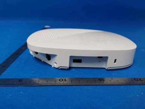
Click to zoom
Application Details
- Equipment Class
- DTS - Digital Transmission System
- Date of Grant
- Jan 01, 2020
- Application Purpose
- Original Equipment
- Date of Application
- Dec 30, 2019
- Equipment Note
- Wireless Access Point
- Frequency Range
- 2412.00000000 - 2462.00000000
- Company
- Extreme Networks, Inc.
- Country
- United States
Documents & Files
Document Text
Text extracted from the exhibit documents filed with the FCC. Open a document above to read the original.
Users Manual
AP410C HardwareUserGuide Readabout andviewspecificationsandcomplianceinformation fortheAP410Cin thistopic.InstalltheAP410Cusingthistopic. The AP410C isahigh-performance 802.11axdual-5G. dualbandaccesspoint designedforindoorhigh-density environments. Thisdevice supports IEEE 802.11axOrthogonalFrequency-Division Multiple Access(OFDMA) multi-useraccess. Forregulatory andcompliance information, see "Regulatory Compliance Statements". Important! Change the Country Code Ifyouraccesspoint isconfiguredforthe WorldRegulatory Domain, it isimportant to set the country code to the country in which the AP willbe deployedto meet regulatory requirementsandforoptimalwirelessoperation. To do this, follow these steps: Thecountrycodeselection isforWorldmodelsonlyandisnot availabletoFCC,CAN,andothercountry-specificmodels.PerFCCreg- ulations,allWi-Fiproductsmarketedin theUnitedStatesmust beset toU.S.channelsonly. 1. Poweron the APandallow it to findandconnect to ExtremeCloud IQ. Once the AP isconnectedit appearsin the table ofdeviceson the Manage>Devicespage. 2. Select the checkboxnext to the AP, andthen chooseAssign Country Codefrom theActionsdrop-down list. In the dialogbox, select the appropriate country from the drop-down list, andthen clickSave. 3. Uploadyourchangesto the device. Safety Guidelines Safety Guidelines The safety information in thissection appliesto AP410C devices. The followingsafety iconsare usedin these guidelinesto identify the type ofprecaution: AP410C Hardware Guide1 AP410C Hardware Guide1 Thisicon indicatesageneralcaution. Failure to comply with acaution notification can result in damage to equipment. Thisicon indicatesan electricalcaution. Failure to comply with an electricalnotification can result in seriousinjury or death, andextensive damage to equipment. Thisicon indicatesalasercaution. Failure to comply with alasercaution can result in seriousinjury. The followingtable liststhe safety precautionsyoushouldfollow when installingyourAP410C devices. Extreme Networksdevicesmust be installedby aprofessionalinstallerwho iscertifiedto installthese typesofdevices andto ensure that they are properly groundedandmeet applicable localandnationalelectricalcodes. These devicesare intendedforindooruse only. Do not installthe device in an environment where the operatingambient temperature might exceedthe recom- mendedranges. Warning: ThisisaClassA product. In adomestic environment thisproduct may cause radio interference in which case the usermay be requiredto take adequate measures. Forproductsavailable in the USA/Canadamarket, forthe 2.4 GHz band, only channels1-11 can be operated. Selec- tion ofotherchannelsisnot possible. Changesormodificationsmade to thisdevice that are not expressly approvedby the party responsible forcom- pliance couldvoidthe user'sauthority to operate the equipment. Use only attachmentsandaccessoriesspecifiedby Extreme Networks. These devicesare not intendedforuse by persons(includingchildren) with reducedphysical, sensory, ormentalcap- abilities, orwith lackofexperience ofknowledge unlessthey are given supervision orinstruction concerninguse ofthe devicesby aperson who isresponsible fortheirsafety. Children shouldbe supervisedto ensure that they do not play with the devices. Electrostatic discharge (ESD) can damage equipment andimpairelectricalcircuitry. ESD damage occurswhen elec- tronic componentsare improperly handledandcan result in complete orintermittent failures. Be sure to follow ESD-pre- vention procedureswhen handlingelectronic componentsandequipment. Duringoperation, the surfacesofthe AP410C can become hot. Use caution when handling. To meet federalradiation exposure requirements, these devicesshouldbe installedat aminimum distance of8"(20 cm) from people oranimals. Install the AP Youcan mount the AP410C on aflat surface orwall, oron the railsofastandarddroppedceilinggrid. There isalso an accessory mountingbracket that allowsyouto installthe device in Armstrong-style droppedceilings(orderedseparately). The followingsectionsdescribe how to installyourAP410C devices. Shipping Carton Contents The AP410C shippingcarton containsthe followingitems: lAP410C chassis lMountingbracket AP410C Hardware Guide2 AP410C Hardware Guide 2 lReadMe card Installthe AP on a Ceiling Track The AP410C shipswith amountingbracket that letsyoueasily installit on the railofastandarddroppedceilinggrid. The followingillustration showshow to attach the bracket to the ceilingrail, andthen installthe AP on the bracket. Once the bracket issecure, installthe APusingthe followingsteps: 1. Align the reddot on the bottom ofthe APwith the reddot on the bracket. 2. Lift the AP straight upandkeepthe reddotsaligneduntilthe bracket isseatedin the rounddepression on the bottom ofthe device. AP410C Hardware Guide4 AP410C Hardware Guide4 3. Rotate the AP clockwise untilit clicksinto place on the bracket. Mountingbracketsare available forthese devicesthat willallow youto installthem on non-standardceilingtracks. The followingaccessory brack- etsare available: lAH-ACC-BKT-AX-IL: Mountingbracket forInterlude ceilings. lAH-ACC-BKT-AX-SL: Mountingbracket forSilhouette 1/8"andSilhouette 1/4"ceilings. lAH-ACC-BKT-AX-TB: Mountingbracket forPrelude 15/16"andSuprafine 9/16"ceilings. lAH-ACC-BKT-AX-WL: Mountingbracket fordirect-to-wallinstallations. AP410C Hardware Guide5 AP410C Hardware Guide5 Use the holesin the bracket asatemplate to markthe wall. Drillholesin the wallandattach the bracket to the wallusingwallscrewsandwall anchorsifnecessary. Attach the AP to the bracket in the same mannerasshown in the previoussection. Lock the AP Youcan secure the APusingaKensington ® lockin the lockslot on the device, oryoucan use asecurity bracket andacrossheadscrew orasecur- ity screw. Security bracketsandscrewscan be orderedseparately from Extreme Networks(not available in Brazil). Extreme Networksrecommendsavariety ofKensington locks. Formore information, contact yoursalesrepresentative. Hardware Components Youcan see the…
Text truncated - open the document above for the full version.
Cover Letter(s)
6480 Via Del Oro / San Jose, CA 95119 / +1-408-579-2800 / ExtremeNetworks.com Declaration Of Authorization Date: 2019-12-18 We Name: Extreme Networks, Inc Address: 6480 Via Del Oro, San Jose, CA 95119 City: San Jose Country: United States Declare that: Agent Company name: DEKRA Testing and Certification (Suzhou) Co., Ltd. Address: No.99 Hongye Rd., Suzhou Industrial Park, 215006 City: Suzhou Country China is authorized to apply for Certification of the following product(s): Product description: Wireless Access Point Type designation: AP410C Trademark: Extreme Networks FCC ID: QXO-AP410C IC: 4141B-AP410C on our behalf. Sincerely, Timothy Wakeley / Compliance Manager Extreme Networks, Inc
Cover Letter(s)
6480 Via Del Oro / San Jose, CA 95119 / +1-408-579-2800 / ExtremeNetworks.com FCC Confidentiality long Term Letter Date:2019-12-18 Federal Communications Commission Authorization and Evaluation Division FCC ID: QXO-AP410C Confidentiality Request Pursuant to Sections 0.457 and 0.459 of the Commission’s Rules, the Applicant hereby requests confidential treatment of information accompanying this Application as outlined below: Schematics Diagram Block Diagram Operational Description SW SECURITY DESCRIPTION The above materials contain trade secrets and proprietary information not customarily released to the public. The public disclosure of these matters might be harmful to the Applicant and provide unjustified benefits to its competitors. Sincerely, Timothy Wakeley / Compliance Manager Extreme Networks, Inc
Cover Letter(s)
6480 Via Del Oro / San Jose, CA 95119 / +1-408-579-2800 / ExtremeNetworks.com Non-SDR-Statement Date: 2019-12-18 Federal Communications Commission Authorization and Evaluation Division ATTESTATION FCC ID: QXO-AP410C Product: Wireless Access Point Model: AP410C Regarding the SDR application guide (KDB442812 D01 SDR Apps Guide v02r03), our answer to the following five questions can be used for determining our device is not an SDR: 1. Can the RF parameters of the device be altered through software? YES 2. Can third parties not permitted by the Commission through specific filings modify, configure, or load different software, or make configuration settings to operate the device or host hardware radio frequency parameters (frequency range, modulation type, maximum output power or other radio parameters) in any other way than granted (or expected to be granted)? NO 3. Is the device capable of operating in any other in any other way than granted, or will be, granted? NO 4. Is this a Part 15 client device as defined in Section 15.202 (as opposed to a master device)? NO 5. Does the manufacturer elect SDR? NO Sincerely, Timothy Wakeley / Compliance Manager Extreme Networks, Inc 6480 Via Del Oro / San Jose, CA 95119 / +1-408-579-2800 / ExtremeNetworks.com
Cover Letter(s)
Extreme Networks, Inc. 6480 Via Del Oro, San Jose, CA 95119, San Jose, United States Request for FCC Grant Revision FCC ID: QXO-AP410C Date: 2021-04-12 TO: Federal Communication Commission & Innovation, Science and Economic Development Canada (ISED) This is to request for FCC Grant Revision, since we didn’t notice that WiFi 2.4G frequency range was wrongly showed in FCC DTS Grant until now, so we’re authorizing Teleficiation B.V. to modify WiFi 2.4G frequency range to 2412-2462, there is not such typo in FCC test report, only wrongly showed in 731 form, Please help approve. Signature: Thomas Whissel / Regulatory Compliance Manager Extreme Networks, Inc
External Photos
Report No: 1992128R-RF-US (1) EUT Photo(AP410C) (2) EUT Photo(AP410C) Report No: 1992128R-RF-US Report No: 1992128R-RF-US (3) EUT Photo(AP410C) (4) EUT Photo(AP410C) Report No: 1992128R-RF-US (5) EUT Photo(AP410C) (6) EUT Photo(AP410C)
ID Label/Location Info
1. MATERIAL: WHITE MATTE PET, HTLW100(EB)J, T=0.1mm ADHESIVE: ACRYLIC T=0.034mm 2. FINISH: FINISH: PET,T=0.025mm 3. COLOR: ORIGINAL MATERIAL COLOR : BLACK, 4. UL APPROVED, PGDQ2. 5. 6.TEMPERATURE RESISTANT= 120 ̊ C 7.:30mm~120mm±0.3mm,120~315mm±0.5mm,315±0.8mm 8. 9. 10.TEST REQUIREMENTS *Ø97.5 *Ø28.4,THR. *R44.35 R1.5 20.97 5° 33.6±0.5 17.9±0.5 R0.5 NOTE: TEST ITEMTEST SPECTEST CONDITIONCRITERIA 1 ����� ISO Class.: 1 ASTM Class.: 4 B ASTM D3359-02/ ISO 2409:2007 Detach ment of small flake s of the co ating at the interse ct ions of the cu ts. A cr oss-cu t area not si gnifica ntly greater than 5% is affect ed. -FCC FCC ID: QXO-AP410C -CAN IC: 4141B-AP410C ICES-3 (B) / NMB-3 (B) -WR See manual before use Extreme Networks Inc. 6480 Via Del Oro, San Jose, CA 95119, USA Patents Pending Made in China 510175 Rev. A Patents: www.extremenetworks.com/patents This device complies with Part 15 of the FCC Rules. Operation is subject to the following two conditions: (1) This device may not cause harmful interference, and (2) this device must accept any interference received, including interference that may cause undesired operation. 201-190727 5GHz R-C-EXR-AP410C CCAH19XXXXXXXXX D33194 RoHS AP410C Label Location
Internal Photos
Report No: 1992128R-RF-US (1) EUT Photo(AP410C) (2) EUT Photo(AP410C) Report No: 1992128R-RF-US Report No: 1992128R-RF-US (3) EUT Photo(AP410C) (4) EUT Photo(AP410C) Report No: 1992128R-RF-US Report No: 1992128R-RF-US (5) EUT Photo(AP410C) (6) EUT Photo(AP410C) Report No: 1992128R-RF-US (7) EUT Photo(AP410C) (8) EUT Photo(AP410C) Report No: 1992128R-RF-US (9) EUT Photo(AP410C)
RF Exposure Info
RF Exposure Evaluation Declaration Product Name : Wireless Access Point Model No. : AP410C FCC ID : QXO-AP410C Applicant : Extreme Networks, Inc Address : 6480 Via Del Oro, San Jose, CA 95119 Date of Receipt : Sep. 20, 2019 Issued Date : Dec. 30, 2019 Report No. : 1992128R-RF-US-P20V01 Report Version : V1.1 The test results presented in this report relate only to the object tested. The measurement result is considered in conformance with the requirement if it is within the prescribed limit, It is not necessary to account the uncertainty associated with the measurement result, unless the specification, standard or customer have special requirements This report shall not be reproduced, except in full, without the written approval of the Issuing CB Testing Laboratory This report is not used for social proof in China (or Mainland China) market. Report No: 1992128R-RF-US-P20V01 Page: 2 of 9 Te s t R e p o r t C e r t i f i c a t i o n Issued Date: Dec. 30, 2019 Report No.: 1992128R-RF-US-P20V01 Product Name : Wireless Access Point Applicant : Extreme Networks, Inc Address : 6480 Via Del Oro, San Jose, CA 95119 Manufacturer : Extreme Networks, Inc Address : 6480 Via Del Oro, San Jose, CA 95119 Model No. : AP410C Brand : Extreme Networks FCC ID : QXO-AP410C EUT Voltage : DC 37~57V Applicable Standard : KDB 447498D01V06 FCC Part1.1310 Test Result : Complied Performed Location : DEKRA Testing and Certification (Suzhou) Co., Ltd. No.99 Hongye Rd., Suzhou Industrial Park, Suzhou, 215006, Jiangsu, China TEL: +86-512-6251-5088 / FAX: +86-512-6251-5098 FCC Designation Number: CN1199 Documented By : (Project Assistant: Kitty Li ) Reviewed By : (Senior Engineer: Frank He ) Approved By : ( Engineer Supervisor: Jack Zhang ) Report No: 1992128R-RF-US-P20V01 Page: 3 of 9 1. RF Exposure Evaluation 1.1. Limits According to FCC 1.1310: The criteria listed in the following table shall be used to evaluate the environment impact of human exposure to radio frequency (RF) radiation as specified in 1.1307(b) LIMITS FOR MAXIMUM PERMISSIBLE EXPOSURE (MPE) Frequency Range (MHz) Electric Field Strength (V/m) Magnetic Field Strength (A/m) Power Density (mW/cm2) Average Time (Minutes) (A) Limits for Occupational/ Control Exposures 300-1500 -- -- F/300 6 1500-100,000 -- -- 5 6 (B) Limits for General Population/ Uncontrolled Exposures 300-1500 -- -- F/1500 6 1500-100,000 -- -- 1 30 F= Frequency in MHz Friis Formula Friis transmission formula: Pd = (Pout*G)/(4*pi*r2) Where Pd = power density in mW/cm2 Pout = output power to antenna in mW G = gain of antenna in linear scale Pi = 3.1416 R = distance between observation point and center of the radiator in cm Pd is the limit of MPE, 1 mW/cm2. If we know the maximum gain of the antenna and the total power input to the antenna, through the calculation, we will know the distance r where the MPE limit is reached. Report No: 1992128R-RF-US-P20V01 Page: 4 of 9 1.2. Test Procedure Software provided by client enabled the EUT to transmit and receive data at lowest, middle and highest channel individually. The temperature and related humidity: 18°Cand 78% RH. 1.3. Test Result of RF Exposure Evaluation Product : Wireless Access Point Test Item : RF Exposure Evaluation Test Site : AC-6 Antenna Information: BLE 2.4GHz: Antenna Model No. N/A Antenna Manufacturer N/A Antenna Delivery 1*TX+1*RX 2*TX+2*RX 3*TX+3*RX Antenna Technology SISO MIMO Basic methodology Sectorized antenna systems Cross-polarized antennas Unequal antenna gains, with equal transmit powers Spatial Multiplexing Cyclic Delay Diversity (CDD) Antenna Type PIFA Antenna Gain 3.4dBi Report No: 1992128R-RF-US-P20V01 Page: 5 of 9 WLAN 2.4GHz: Antenna Model No. N/A Antenna Manufacturer N/A Antenna Delivery 1*TX+1*RX 2*TX+2*RX 3*TX+3*RX Antenna Technology SISO MIMO Basic methodology Sectorized antenna systems Cross-polarized antennas Unequal antenna gains, with equal transmit powers Spatial Multiplexing Cyclic Delay Diversity (CDD) Antenna Type PIFA Antenna Gain(Radio 1) Antenna Technology Ant Gain (dBi) Ant 4(Radio 1) 4.00 Antenna Gain(Radio 2) Antenna Technology Ant Gain (dBi) SISO Ant1 (Radio 2) 3.80 Ant2 (Radio 2) 3.90 CDD 3.90dBi for Power; 6.91dBi for PSD Beam-forming 6.91dBi for Power; 6.91dBi for PSD Report No: 1992128R-RF-US-P20V01 Page: 6 of 9 WLAN 5GHz: Antenna Model No. N/A Antenna Manufacturer N/A Antenna Delivery 1*TX+1*RX 2*TX+2*RX 3*TX+3*RX 4*TX+4*RX Antenna Technology SISO MIMO Basic methodology Sectorized antenna systems Cross-polarized antennas Unequal antenna gains, with equal transmit powers Spatial Multiplexing Cyclic Delay Diversity (CDD) Antenna Type PIFA Antenna Gain(Radio 1) Antenna Technology Ant Gain (dBi) Ant 4(Radio 1) 3.3 Antenna Gain(Radio 2) Antenna Technology Ant Gain (dBi) SISO Ant1 (Radio 2) 4.5 Ant2 (Radio 2) 4.7 CDD 4.7dBi for Power; 7.71dBi for PSD Beam-forming 7.71dBi for Power; 7.71dBi for PSD Report No: 1992128R-RF-US-P20V01 Page: 7 of 9 Antenna Gain(Radio 3) Antenna Technology Ant Gain (dBi) SISO Ant3 (Radio 3) 4.7 Ant5 (Radio 3) 4.6 Ant6 (Radio 3) 4.6 Ant7 (Radio 3) 4.7 2*2 CDD 4.7dBi for Power; 7.71dBi for PSD 2*2 Beam-forming 7.71dBi for Power; 7.71dBi for PSD 4*4 CDD 4.7dBi for Power; 10.72dBi for PSD 4*4 Beam-forming 10.72dBi for Power; 10.72dBi for PSD Note: The device supports 3 radios, radio 1(1*1 2.4GHz & 1*1 5GHz full band); radio 2(2*2 2.4GHz & 2*2 5GHz low band); radio 3(4*4 5GHz full band & 1*1 BLE), and radio 2 & 3 can works with Dual 2.4GHz & 5GHz mode and Dual 5GHz mode. As the 5GHz high band filter is different between two modes, additional Radio 3 5GHz high band mode is tested for compliance. Dual 2.4GHz & 5GHz mode: Radio 2(2.4GHz 2*2) + Radio 3(5GHz full band 4*4) Dual 5GHz mode: Radio 2(5GHz low band 2*2) + Radio 3(5GHz high band 4*4) Report No: 1992128R-RF-US-P20V01 Page: 8 of 9 Power Density Standalone modes: AP410C: Wireless Radio Test Mode Frequency Band (MHz) Maximum EIRP (dBm) Power Density at R = 20cm (mW/cm2) Power Density Limit at R = 20 cm (mW/cm2) Radio 3 BLE 2…
Text truncated - open the document above for the full version.
Test Report
Test Report FCC Part15 Subpart C & RSS-247 Issue 2 Product Name : Wireless Access Point Model No. : AP410C FCC ID : QXO-AP410C IC : 4141B-AP410C Applicant : Extreme Networks, Inc Address : 6480 Via Del Oro, San Jose, CA 95119 Date of Receipt : Sep. 20, 2019 Test Date : Oct. 14, 2019~ Nov. 08, 2019 Issued Date : Dec. 24, 2019 Report No. : 1992128R-RF-US-P06V02 Report Version : V 1.0 The test results presented in this report relate only to the object tested. The measurement result is considered in conformance with the requirement if it is within the prescribed limit, It is not necessary to account the uncertainty associated with the measurement result, unless the specification, standard or customer have special requirements This report shall not be reproduced, except in full, without the written approval of the Issuing CB Testing Laboratory This report is not used for social proof in China (or Mainland China) market. Report No: 1992128R-RF-US-P06V02 Page: 2 of 63 Test Report Certification Issued Date : Dec. 24, 2019 Report No. : 1992128R-RF-US-P06V02 Product Name : Wireless Access Point Applicant : Extreme Networks, Inc Address : 6480 Via Del Oro, San Jose, CA 95119 Manufacturer : Extreme Networks, Inc Address : 6480 Via Del Oro, San Jose, CA 95119 Model No. : AP410C Brand : Extreme Networks FCC ID : QXO-AP410C IC : 4141B-AP410C EUT Voltage : DC 37~57V Test Voltage : AC 120V/60Hz Applicable Standard : FCC CFR Title 47 Part 15 Subpart C ANSI C63.10:2013; KDB 558074 D01v05r02 RSS-Gen Issue 5 + Amendment 1/ RSS-247 Issue 2 Test Result : Complied Performed Location : DEKRA Testing & Certification (Suzhou) Co., Ltd. No.99 Hongye Rd., Suzhou Industrial Park, Suzhou, 215006, Jiangsu, China TEL: +86-512-6251-5088 / FAX: +86-512-6251-5098 FCC Designation Number: CN1199; ISED CAB identifier: CN0040 Documented By : (Project Assistant: Kitty Li) Reviewed By : (Senior Engineer: Frank He ) Approved By : (Engineer Supervisor: Jack Zhang ) Report No: 1992128R-RF-US-P06V02 Page: 3 of 63 TABLE OF CONTENTS Description Page 1. General Information ................................................................................................. 6 1.1. EUT Description ...................................................................................................... 6 1.2. Working Frequency of Each Channel: ..................................................................... 7 1.3. Antenna information ................................................................................................ 8 1.4. Mode of Operation ................................................................................................... 9 1.5. Tested System Details ............................................................................................. 9 1.6. Configuration of Tested System ............................................................................. 10 1.7. EUT Exercise Software .......................................................................................... 11 2. Technical Test ........................................................................................................ 12 2.1. Summary of Test Result ......................................................................................... 12 2.2. Test Frequency configuration: ................................................................................ 14 2.3. Test Environment ................................................................................................... 15 2.4. Measurement Uncertainty ...................................................................................... 15 3. AC Power Line Conducted Emission ..................................................................... 16 3.1. Test Equipment ...................................................................................................... 16 3.2. Test Setup.............................................................................................................. 16 3.3. Limit ....................................................................................................................... 17 3.4. Test Procedure ...................................................................................................... 17 3.5. Test Result ............................................................................................................. 18 4. Emissions in restricted frequency bands ............................................................... 18 4.1. Test Equipment ...................................................................................................... 20 4.2. Test Setup.............................................................................................................. 21 4.3. Limit ....................................................................................................................... 22 4.4. Test Procedure ...................................................................................................... 25 4.5. EUT test Axis definition .......................................................................................... 26 4.6. Test Result ............................................................................................................. 27 5. Emissions in non-restricted frequency bands ........................................................ 37 5.1. Test Equipment ...................................................................................................... 37 5.2. Test Setup.............................................................................................................. 37 5.3. Limit ....................................................................................................................... 38 5.4. Test Procedure ...................................................................................................... 39 5.5. EUT test Axis definition .......................................................................................... 40 5.…
Text truncated - open the document above for the full version.
Test Report
Test Report FCC Part15 Subpart C & RSS-247 Issue 2 Product Name : Wireless Access Point Model No. : AP410C FCC ID : QXO-AP410C IC : 4141B-AP410C Applicant : Extreme Networks, Inc Address : 6480 Via Del Oro, San Jose, CA 95119 Date of Receipt : Sep. 20, 2019 Test Date : Oct. 14, 2019~ Nov. 27, 2019 Issued Date : Dec. 30, 2019 Report No. : 1992128R-RF-US-P06V01 Report Version : V1.1 The test results presented in this report relate only to the object tested. The measurement result is considered in conformance with the requirement if it is within the prescribed limit, It is not necessary to account the uncertainty associated with the measurement result, unless the specification, standard or customer have special requirements This report shall not be reproduced, except in full, without the written approval of the Issuing CB Testing Laboratory This report is not used for social proof in China (or Mainland China) market. Report No: 1992128R-RF-US-P06V01 Page: 2 of 126 Te s t R e p o r t C e r t i f i c a t i o n Issued Date: Dec. 30, 2019 Report No. : 1992128R-RF-US-P06V01 Product Name : Wireless Access Point Applicant : Extreme Networks, Inc Address : 6480 Via Del Oro, San Jose, CA 95119 Manufacturer : Extreme Networks, Inc Address : 6480 Via Del Oro, San Jose, CA 95119 Model No. : AP410C Brand : Extreme Networks FCC ID : QXO-AP410C IC : 4141B-AP410C EUT Voltage : DC 37~57V Test Voltage : AC 120V/60Hz Applicable Standard : FCC CFR Title 47 Part 15 Subpart C ANSI C63.10:2013; KDB 558074 D01v05r02 KDB 662911 D01 Multiple Transmitter Output v02r01 RSS-Gen Issue 5 / RSS-247 Issue 2 Test Result : Complied Performed Location : DEKRA Testing and Certification (Suzhou) Co., Ltd. No.99 Hongye Rd., Suzhou Industrial Park, Suzhou, 215006, Jiangsu, China TEL: +86-512-6251-5088 / FAX: +86-512-6251-5098 FCC Designation Number: CN1199 ISED CAB identifier: CN0040 Documented By : ( Adm. Specialist: Kitty Li ) Reviewed By : (Technical Supervisor: Frank He) Approved By : (Engineer Supervisor: Jack Zhang ) Report No: 1992128R-RF-US-P06V01 Page: 3 of 126 TABLE OF CONTENTS Description Page 1. General Information ................................................................................................. 6 1.1. EUT Description ...................................................................................................... 6 1.2. Working Frequency of Each Channel: ..................................................................... 7 1.3. Antenna information ................................................................................................ 8 1.4. Mode of Operation ................................................................................................... 9 1.5. Tested System Details ............................................................................................. 9 1.6. Configuration of Tested System ............................................................................. 10 1.7. EUT Exercise Software .......................................................................................... 11 2. Technical Test ........................................................................................................ 12 2.1. Summary of Test Result......................................................................................... 12 2.2. Test Frequency configuration:................................................................................ 14 2.3. Power vs Data Rate ............................................................................................... 15 2.4. Test Environment ................................................................................................... 17 2.5. Measurement Uncertainty...................................................................................... 17 3. AC Power Line Conducted Emission ..................................................................... 18 3.1. Test Equipment ...................................................................................................... 18 3.2. Test Setup.............................................................................................................. 18 3.3. Limit ....................................................................................................................... 19 3.4. Test Procedure ...................................................................................................... 19 3.5. Test Result ............................................................................................................. 20 4. Emissions in restricted frequency bands ............................................................... 22 4.1. Test Equipment ...................................................................................................... 22 4.2. Test Setup.............................................................................................................. 23 4.3. Limit ....................................................................................................................... 24 4.4. Test Procedure ...................................................................................................... 27 4.5. EUT test Axis definition .......................................................................................... 28 4.6. Test Result ............................................................................................................. 29 5. Emissions in non-restricted frequency bands ........................................................ 34 5.1. Test Equipment ...................................................................................................... 34 5.2. Test Setup.............................................................................................................. 35 5.3. Limit ....................................................................................................................... 36 5.4. Test Procedure ...................................................…
Text truncated - open the document above for the full version.
Test Report
1 Appendix 2: Radiated spurious emission Radio 1: Profile: 1992128R Page No.: 25 Engineer: YULIU Site: AC5 Time: 2019/11/14 - 02:44 Limit: FCC_Part15.209_RE(3m) Margin: 0 Probe: Horn_3117_00167055(1-18GHz) Polarity: Vertical EUT: AP410C Power: AC 120V/60Hz Note: Mode 1:Transmit at 2412MHz by 802.11b No Mark Frequency (MHz) Measure Level (dBuV/m) Reading Level (dBuV) Over Limit (dB) Limit (dBuV/m) Factor (dB) Type 1 4824.000 40.665 35.973-33.33574.0004.692 PK 2 * 7236.000 44.752 35.175-29.24874.0009.576 PK 3 9648.000 44.107 34.284-29.89374.0009.823 PK 2 Profile: 1992128R Page No.: 26 Engineer: YULIU Site: AC5 Time: 2019/11/14 - 02:45 Limit: FCC_Part15.209_RE(3m) Margin: 0 Probe: Horn_3117_00167055(1-18GHz) Polarity: Horizontal …
Text truncated - open the document above for the full version.
Contact Information
Applicant
John Ballew(Senior Regulatory Compliance Manager)
Technical Contact
DEKRA Testing and Certification (Suzhou) Co., Ltd.Jack Zhang
[email protected]0512-62515088
No.99 Hongye RD.Suzhou Industrial Park, · China
Non-Technical Contact
DEKRA Testing and Certification (Suzhou) Co., Ltd.Yuki Li
[email protected]0512-62515088
Test Firm
DEKRA Testing and Certification (Suzhou) Co., Ltd.Janet Xu
[email protected]86 512 6251 50885113
Technical Specifications
| # | Rule Parts | Frequency Range | Power Output |
|---|---|---|---|
| 2 | 15C | 2.41 GHz - 2.46 GHz | 310.00 mW |
Other Applications from Extreme Networks, Inc.
QXO-AP4000
Jul 07, 2026Access Point
Equipment Class
6SD - 15E 6 GHz Standard Power Access PointQXO-AP3020W
Jun 23, 2026Access Point
Equipment Class
DTS - Digital Transmission SystemQXO-AP5022
Jun 04, 2026Access Point
Equipment Class
DTS - Digital Transmission SystemQXO-AP5010
Apr 07, 2026Access Point
Equipment Class
6SD - 15E 6 GHz Standard Power Access PointQXO-AP5060
Feb 18, 2026Access Point
Equipment Class
NII - Unlicensed National Information Infrastructure TX