QXO-OAP36BHiPath Wireless Outdoor Access Point
Extreme Networks, Inc.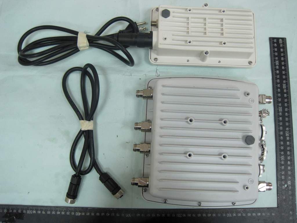
Click to zoom
Application Details
- Equipment Class
- DTS - Digital Transmission System
- Date of Grant
- Dec 22, 2010
- Application Purpose
- Original Equipment
- Date of Application
- Dec 22, 2010
- Equipment Note
- HiPath Wireless Outdoor Access Point
- Frequency Range
- 5755.00000000 - 5795.00000000
- Company
- Extreme Networks, Inc.
- Country
- United States
Documents & Files
Document Text
Text extracted from the exhibit documents filed with the FCC. Open a document above to read the original.
Users Manual
Communication for the open minded Siemens Enterprise Communications www.siemens.com/open Documentation HiPath Wireless Controller, Access Points and Convergence Software V7.31 User Guide 9034530-04 Copyright ©Siemens Enterprise Communications GmbH & Co. KG 2010 Hofmannstr. 51, 80200 München Siemens Enterprise Communications GmbH & Co. KG is a Trademark Licensee of Siemens AG Reference No.: 9034530-04 The information provided in this document contains merely general descriptions or characteristics of performance which in case of actual use do not always apply as described or which may change as a result of fur- ther development of the products. An obligation to pro- vide the respective characteristics shall only exist if ex- pressly agreed in the terms of contract. Availability and technical specifications are subject to change without no- tice. OpenScape, OpenStage and HiPath are registered trade- marks of Siemens Enterprise Communications GmbH & Co. KG. All other company, brand, product and service names are trademarks or registered trademarks of their respective holders. Siemens Enterprise Communications www.siemens.com/open Communication for the open minded hwc_user_guideTOC.fm 9034530-04, September 2010 HiPath Wireless Controller, Access Points and Convergence Software V7.31, User Guide3 Nur für den internen GebrauchContents Contents0 1 About this Guide . . . . . . . . . . . . . . . . . . . . . . . . . . . . . . . . . . . . . . . . . . . . . . . . . . . . . . . . . . . . . . . . . . . . . . 11 1.1 Who should use this guide . . . . . . . . . . . . . . . . . . . . . . . . . . . . . . . . . . . . . . . . . . . . . . . . . . . . . . . . . . . . . . 11 1.2 What is in this guide . . . . . . . . . . . . . . . . . . . . . . . . . . . . . . . . . . . . . . . . . . . . . . . . . . . . . . . . . . . . . . . . . . . 11 1.3 Formatting conventions . . . . . . . . . . . . . . . . . . . . . . . . . . . . . . . . . . . . . . . . . . . . . . . . . . . . . . . . . . . . . . . . 13 1.4 Additional documentation. . . . . . . . . . . . . . . . . . . . . . . . . . . . . . . . . . . . . . . . . . . . . . . . . . . . . . . . . . . . . . . 13 1.5 Getting Help . . . . . . . . . . . . . . . . . . . . . . . . . . . . . . . . . . . . . . . . . . . . . . . . . . . . . . . . . . . . . . . . . . . . . . . . . 14 1.6 Safety Information . . . . . . . . . . . . . . . . . . . . . . . . . . . . . . . . . . . . . . . . . . . . . . . . . . . . . . . . . . . . . . . . . . . . 14 1.7 Sicherheitshinweise . . . . . . . . . . . . . . . . . . . . . . . . . . . . . . . . . . . . . . . . . . . . . . . . . . . . . . . . . . . . . . . . . . . 16 1.8 Consignes de sécurité . . . . . . . . . . . . . . . . . . . . . . . . . . . . . . . . . . . . . . . . . . . . . . . . . . . . . . . . . . . . . . . . . 17 2 Overview of the HiPath Wireless Controller, Access Points and Convergence Software solution . . . 19 2.1 Conventional wireless LANs . . . . . . . . . . . . . . . . . . . . . . . . . . . . . . . . . . . . . . . . . . . . . . . . . . . . . . . . . . . . 20 2.2 Elements of the HiPath Wireless Controller, Access Points and Convergence Software solution . . . . . . . 22 2.2.1 Enterasys NetSight Suite integration . . . . . . . . . . . . . . . . . . . . . . . . . . . . . . . . . . . . . . . . . . . . . . . . . . 26 2.3 HiPath Wireless Controller, Access Points and Convergence Software and your network . . . . . . . . . . . . . 27 2.3.1 Network traffic flow . . . . . . . . . . . . . . . . . . . . . . . . . . . . . . . . . . . . . . . . . . . . . . . . . . . . . . . . . . . . . . . . 29 2.3.2 Network security . . . . . . . . . . . . . . . . . . . . . . . . . . . . . . . . . . . . . . . . . . . . . . . . . . . . . . . . . . . . . . . . . . 31 2.3.2.1 Authentication . . . . . . . . . . . . . . . . . . . . . . . . . . . . . . . . . . . . . . . . . . . . . . . . . . . . . . . . . . . . . . . . 32 2.3.2.2 Privacy. . . . . . . . . . . . . . . . . . . . . . . . . . . . . . . . . . . . . . . . . . . . . . . . . . . . . . . . . . . . . . . . . . . . . . 32 2.3.3 Virtual Network Services. . . . . . . . . . . . . . . . . . . . . . . . . . . . . . . . . . . . . . . . . . . . . . . . . . . . . . . . . . . . 33 2.3.4 VNS components . . . . . . . . . . . . . . . . . . . . . . . . . . . . . . . . . . . . . . . . . . . . . . . . . . . . . . . . . . . . . . . . . 34 2.3.4.1 Topology . . . . . . . . . . . . . . . . . . . . . . . . . . . . . . . . . . . . . . . . . . . . . . . . . . . . . . . . . . . . . . . . . . . . 34 2.3.4.2 Policy . . . . . . . . . . . . . . . . . . . . . . . . . . . . . . . . . . . . . . . . . . . . . . . . . . . . . . . . . . . . . . . . . . . . . . . 35 2.3.4.3 WLAN Services . . . . . . . . . . . . . . . . . . . . . . . . . . . . . . . . . . . . . . . . . . . . . . . . . . . . . . . . . . . . . . . 36 2.3.5 Static routing and routing protocols . . . . . . . . . . . . . . . . . . . . . . . . . . . . . . . . . . . . . . . . . . . . . . . . . . . 36 2.3.6 Mobility and roaming. . . . . . . . . . . . . . . . . . . . . . . . . . . . . . . . . . . . . . . . . . . . . . . . . . . . . . . . . . . . . . . 37 2.3.7 Network availability . . . . . . . . . . . . . . . . . . . . . . . . . . . . . . . . . . . . . . . . . . . . . . . . . . . . . . . . . . . . . . . . 38 2.3.8 Quality of Service (QoS) . . . . . . . . . . . . . . . . . . . . . . . . . . . . . . . . . . . . . . . . . . . . . . . . . . . . . . . . . . . . 38 2.4 HiPath Wireless Controller product family . . . . . . . . . . . . . . . . . . . . . . . . . . . . . . . . . . . . . . . . . . . . . . . . . . 39 3 Configuring the HiPath Wireless Controller . . . . . . . . . . . . . . . . . . . . . . . . . . . . . . . . . . . . . . . . . . . . . . . . 41 3.1 System configuration overview . . . . . . . . . . . . . . . . . . . . . . . . . . . . . . . . . . . . . . . . . . . . . . . . . . . . . . . . . . 41 3.2 Logging on to the HiPath Wireless Controller . . . . . . . . . . . . . . . . . . . . . . . . .…
Text truncated - open the document above for the full version.
Users Manual
hwc_fastfailover.fm Availability and session availability Viewing the Wireless AP availability display 9034530-04, September 2010 HiPath Wireless Controller, Access Points and Convergence Software V7.31, User Guide429 7.5 Viewing the Wireless AP availability display For more information, see Section 11.3, “Viewing the Wireless AP availability display”, on page 455. 7.6 Viewing SLP activity In normal operations, the primary HiPath Wireless Controller registers as an SLP service called ac_manager. The controller service directs the Wireless APs to the appropriate HiPath Wireless Controller. During an outage, if the remaining HiPath Wireless Controller is the secondary controller, it registers as the SLP service ru_manager. To view SLP activity: 1. From the main menu, click Wireless AP Configuration. The Wireless APs screen is displayed. 2. In the left pane, click AP Registration. The Wireless AP Registration screen is displayed. 3. To confirm SLP registration, click View SLP Registration. A pop-up screen displays the results of the diagnostic slpdump tool, to confirm SLP registration. Availability and session availability hwc_fastfailover.fm Viewing SLP activity 9034530-04, September 2010 430HiPath Wireless Controller, Access Points and Convergence Software V7.31, User Guide hwc_mobility.fm Configuring Mobility Mobility overview 9034530-04, September 2010 HiPath Wireless Controller, Access Points and Convergence Software V7.31, User Guide431 8 Configuring Mobility This chapter describes the mobility concept, including: •Mobility overview •Mobility domain topologies •Configuring mobility domain 8.1 Mobility overview The HiPath Wireless Controller, Access Points and Convergence Software system allows up to 12 HiPath Wireless Controllers on a network to discover each other and exchange information about a client session. This technique enables a wireless device user to roam seamlessly between different Wireless APs on different HiPath Wireless Controllers. The solution introduces the concept of a mobility manager; one HiPath Wireless Controller on the network is designated as the mobility manager and all others are designated as mobility agents. The wireless device keeps the IP address, and the service assignments it received from its home HiPath Wireless Controller—the HiPath Wireless Controller that it first connected to. The WLAN Service on each HiPath Wireless Controller must have the same SSID and RF privacy parameter settings. You have two options for choosing the mobility manager: •Rely on SLP with DHCP Option 78 •Define at the agent the IP address of the mobility manager. By explicitly defining the IP address, the agent and the mobility manager are able to find each other directly without using the SLP discovery mechanisms. Direct IP definition is recommended to provide tighter control of the registration steps for multi-domain installations. The HiPath Wireless Controller designated as the mobility manager: •Is explicitly identified as the manager for a specific mobility domain. Agents will connect to this manager to establish a mobility domain. •Defines at the agent the IP address of the mobility manager, which allows for the bypass of SLP. Agents directly find and attempt to register with the mobility manager. •Uses SLP, if this method is preferred, to register itself with the SLP Directory Agent as SiemensNet. •Defines the registration behavior for a multi-controller mobility domain set: Configuring Mobility hwc_mobility.fm Mobility overview 9034530-04, September 2010 432HiPath Wireless Controller, Access Points and Convergence Software V7.31, User Guide •Open mode – A new agent is automatically able to register itself with the mobility manager and immediately becomes part of the mobility domain •Secure mode – The mobility manager does not allow a new agent to automatically register. Instead, the connection with the new agent is placed in pending state until the administrator approves the new device. •Listens for connection attempts from mobility agents. •Establishes connections and sends a message to the mobility agent specifying the heartbeat interval, and the mobility manager's IP address if it receives a connection attempt from the agent. •Sends regular heartbeat messages containing wireless device session changes and agent changes to the mobility agents and waits for a returned update message The HiPath Wireless Controller designated as a mobility agent does the following: •Uses SLP or a statically configured IP address to locate the mobility manager •Defines at the agent the IP address of the mobility manager, which allows for the bypass of SLP. Agents directly find and attempt to register with the mobility manager. •Attempts to establish a TCP/IP connection with the mobility manager •Sends updates, in response to the heartbeat message, on the wireless device users and the data tunnels to the mobility manager. If a controller configured as the mobility manager is lost, the following occurs: •Agent to agent connections remain active. •Mobility agents continue to operate based on the mobility information last coordinated before the manager link was lost. The mobility location list remains relatively unaffected by the controller failure. Only entries associated with the failed controller are cleared from the registration list, and users that have roamed from the manager controller to other agents are terminated and required to re-register as local users with the agent where they are currently located. •The data link between active controllers remains active after the loss of a mobility manager •Mobility agents continue to use the last set of mobility location lists to service known users •Existing users remain in the mobility scenario, and if the users are known to the mobility domain, they continue to be able to roam between connected controllers •New users become local at attaching controller hwc_mobility.fm Configuring Mobility Mobility domain topologies 9034530-04, Septembe…
Text truncated - open the document above for the full version.
External Photos
SPORTON International Inc. PAGE NUMBER : A1 OF A20 TEL : 886-2-2696-2468 ISSUED DATE : Oct. 22, 2010 FAX : 886-2-2696-2255 APPENDIX A. Photographs of EUT SPORTON International Inc. PAGE NUMBER : A2 OF A20 TEL : 886-2-2696-2468 ISSUED DATE : Oct. 22, 2010 FAX : 886-2-2696-2255 SPORTON International Inc. PAGE NUMBER : A3 OF A20 TEL : 886-2-2696-2468 ISSUED DATE : Oct. 22, 2010 FAX : 886-2-2696-2255 SPORTON International Inc. PAGE NUMBER : A4 OF A20 TEL : 886-2-2696-2468 ISSUED DATE : Oct. 22, 2010 FAX : 886-2-2696-2255 SPORTON International Inc. PAGE NUMBER : A5 OF A20 TEL : 886-2-2696-2468 ISSUED DATE : Oct. 22, 2010 FAX : 886-2-2696-2255 SPORTON International Inc. PAGE NUMBER : A6 OF A20 TEL : 886-2-2696-2468 ISSUED DATE : Oct. 22, 2010 FAX : 886-2-2696-2255 SPORTON International Inc. PAGE NUMBER : A7 OF A20 TEL : 886-2-2696-2468 ISSUED DATE : Oct. 22, 2010 FAX : 886-2-2696-2255 SPORTON International Inc. PAGE NUMBER : A8 OF A20 TEL : 886-2-2696-2468 ISSUED DATE : Oct. 22, 2010 FAX : 886-2-2696-2255 SPORTON International Inc. PAGE NUMBER : A9 OF A20 TEL : 886-2-2696-2468 ISSUED DATE : Oct. 22, 2010 FAX : 886-2-2696-2255 SPORTON International Inc. PAGE NUMBER : A10 OF A20 TEL : 886-2-2696-2468 ISSUED DATE : Oct. 22, 2010 FAX : 886-2-2696-2255 Antenna 1 APPENDIX A. Photographs of EUT SPORTON International Inc. PAGE NUMBER : A11 OF A20 TEL : 886-2-2696-2468 ISSUED DATE : Oct. 22, 2010 FAX : 886-2-2696-2255 SPORTON International Inc. PAGE NUMBER : A12 OF A20 TEL : 886-2-2696-2468 ISSUED DATE : Oct. 22, 2010 FAX : 886-2-2696-2255 Antenna 2 SPORTON International Inc. PAGE NUMBER : A13 OF A20 TEL : 886-2-2696-2468 ISSUED DATE : Oct. 22, 2010 FAX : 886-2-2696-2255 Antenna 3 SPORTON International Inc. PAGE NUMBER : A14 OF A20 TEL : 886-2-2696-2468 ISSUED DATE : Oct. 22, 2010 FAX : 886-2-2696-2255 SPORTON International Inc. PAGE NUMBER : A15 OF A20 TEL : 886-2-2696-2468 ISSUED DATE : Oct. 22, 2010 FAX : 886-2-2696-2255 Antenna 4 SPORTON International Inc. PAGE NUMBER : A16 OF A20 TEL : 886-2-2696-2468 ISSUED DATE : Oct. 22, 2010 FAX : 886-2-2696-2255 Antenna 5 SPORTON International Inc. PAGE NUMBER : A17 OF A20 TEL : 886-2-2696-2468 ISSUED DATE : Oct. 22, 2010 FAX : 886-2-2696-2255 Antenna 6 SPORTON International Inc. PAGE NUMBER : A18 OF A20 TEL : 886-2-2696-2468 ISSUED DATE : Oct. 22, 2010 FAX : 886-2-2696-2255 Antenna 7 SPORTON International Inc. PAGE NUMBER : A19 OF A20 TEL : 886-2-2696-2468 ISSUED DATE : Oct. 22, 2010 FAX : 886-2-2696-2255 Antenna Cable SPORTON International Inc. PAGE NUMBER : A20 OF A20 TEL : 886-2-2696-2468 ISSUED DATE : Oct. 22, 2010 FAX : 886-2-2696-2255
ID Label/Location Info
75.00mm 35.00mm
Internal Photos
SPORTON International Inc. PAGE NUMBER : A1 OF A14 TEL : 886-2-2696-2468 ISSUED DATE : Oct. 22, 2010 FAX : 886-2-2696-2255 APPENDIX A. Photographs of EUT SPORTON International Inc. PAGE NUMBER : A2 OF A14 TEL : 886-2-2696-2468 ISSUED DATE : Oct. 22, 2010 FAX : 886-2-2696-2255 SPORTON International Inc. PAGE NUMBER : A3 OF A14 TEL : 886-2-2696-2468 ISSUED DATE : Oct. 22, 2010 FAX : 886-2-2696-2255 SPORTON International Inc. PAGE NUMBER : A4 OF A14 TEL : 886-2-2696-2468 ISSUED DATE : Oct. 22, 2010 FAX : 886-2-2696-2255 SPORTON International Inc. PAGE NUMBER : A5 OF A14 TEL : 886-2-2696-2468 ISSUED DATE : Oct. 22, 2010 FAX : 886-2-2696-2255 SPORTON International Inc. PAGE NUMBER : A6 OF A14 TEL : 886-2-2696-2468 ISSUED DATE : Oct. 22, 2010 FAX : 886-2-2696-2255 SPORTON International Inc. PAGE NUMBER : A7 OF A14 TEL : 886-2-2696-2468 ISSUED DATE : Oct. 22, 2010 FAX : 886-2-2696-2255 SPORTON International Inc. PAGE NUMBER : A8 OF A14 TEL : 886-2-2696-2468 ISSUED DATE : Oct. 22, 2010 FAX : 886-2-2696-2255 SPORTON International Inc. PAGE NUMBER : A9 OF A14 TEL : 886-2-2696-2468 ISSUED DATE : Oct. 22, 2010 FAX : 886-2-2696-2255 SPORTON International Inc. PAGE NUMBER : A10 OF A14 TEL : 886-2-2696-2468 ISSUED DATE : Oct. 22, 2010 FAX : 886-2-2696-2255 SPORTON International Inc. PAGE NUMBER : A11 OF A14 TEL : 886-2-2696-2468 ISSUED DATE : Oct. 22, 2010 FAX : 886-2-2696-2255 SPORTON International Inc. PAGE NUMBER : A12 OF A14 TEL : 886-2-2696-2468 ISSUED DATE : Oct. 22, 2010 FAX : 886-2-2696-2255 SPORTON International Inc. PAGE NUMBER : A13 OF A14 TEL : 886-2-2696-2468 ISSUED DATE : Oct. 22, 2010 FAX : 886-2-2696-2255 SPORTON International Inc. PAGE NUMBER : A14 OF A14 TEL : 886-2-2696-2468 ISSUED DATE : Oct. 22, 2010 FAX : 886-2-2696-2255
RF Exposure Info
Report No.: FR072010 FCC ID: QXO-OAP36B Page No. : C1 of C5 Appendix C. Maximum Permissible Exposure Report No.: FR072010 FCC ID: QXO-OAP36B Page No. : C2 of C5 1. Maximum Permissible Exposure 1.1. Applicable Standard Systems operating under the provisions of this section shall be operated in a manner that ensures that the public is not exposed to radio frequency energy levels in excess limit for maximum permissible exposure. In accordance with 47 CFR FCC Part 2 Subpart J, section 2.1091 this device has been defined as a mobile device whereby a distance of 0.2 m normally can be maintained between the user and the device. (A) Limits for Occupational / Controlled Exposure Frequency Range (MHz) Electric Field Strength (E) (V/m) Magnetic Field Strength (H) (A/m) Power Density (S) (mW/ cm²) Averaging Time |E|²,|H|² or S (minutes) 0.3-3.0 614 1.63 (100)* 6 3.0-30 1842 / f 4.89 / f (900 / f)* 6 30-300 61.4 0.163 1.0 6 300-1500 F/300 6 1500-100,000 5 6 (B) Limits for General Population / Uncontrolled Exposure Frequency Range (MHz) Electric Field Strength (E) (V/m) Magnetic Field Strength (H) (A/m) Power Density (S) (mW/ cm²) Averaging Time |E|²,|H|² or S (minutes) 0.3-1.34 614 1.63 (100)* 30 1.34-30 824/f 2.19/f (180/f)* 30 30-300 27.5 0.073 0.2 30 300-1500 F/1500 30 1500-100,000 1.0 30 Note: f = frequency in MHz ; *Plane-wave equivalent power density 1.2. MPE Calculation Method E (V/m) = d GP××30 Power Density: Pd (W/m²) = 377 2 E E = Electric field (V/m) P = Peak RF output power (W) G = EUT Antenna numeric gain (numeric) d = Separation distance between radiator and human body (m) The formula can be changed to Pd = 2 377 30 d GP × ×× From the peak EUT RF output power, the minimum mobile separation distance, d=1m, as well as the gain of the used antenna, the RF power density can be obtained. Report No.: FR072010 FCC ID: QXO-OAP36B Page No. : C3 of C5 1.3. Calculated Result and Limit 1.3.1. For 5GHz Band <For Mode 1 (Ant. 1)>: For 5GHz ISM Band: (15.247) Antenna Type : Sector Antenna Max Conducted Power for IEEE 802.11an MCS8 20MHz J2+J4: 20.59 dBm Antenna Gain (dBi) Antenna Gain (numeric) Peak Output Power (dBm) Peak Output Power ( mW ) Power Density (S) (mW/cm²) Limit of Power Density (S) (mW/cm²) Test Result 15.00 31.6228 20.5863 114.4548 0.028817 1 Complies <For Mode 2 (Ant. 2)>: For 5GHz ISM Band: (15.247) Antenna Type : Dipole Antenna Max Conducted Power for IEEE 802.11an MCS8 20MHz J2+J4: 27.56 dBm Antenna Gain (dBi) Antenna Gain (numeric) Peak Output Power (dBm) Peak Output Power ( mW ) Power Density (S) (mW/cm²) Limit of Power Density (S) (mW/cm²) Test Result 22.00 158.4893 27.5615 570.3548 0.719707 1 Complies <For Mode 4 (Ant. 4)>: For 5GHz ISM Band: (15.247) Antenna Type : Sector Antenna Max Conducted Power for IEEE 802.11a J2+J3+J4: 28.60 dBm Antenna Gain (dBi) Antenna Gain (numeric) Peak Output Power (dBm) Peak Output Power ( mW ) Power Density (S) (mW/cm²) Limit of Power Density (S) (mW/cm²) Test Result 4.00 2.5119 28.6017 724.7165 0.014494 1 Complies <For Mode 6 (Ant. 6)>: For 5GHz ISM Band: (15.247) Antenna Type : Omni Antenna Max Conducted Power for IEEE 802.11an MCS8 20MHz J2+J3+J4: 25.48 dBm Antenna Gain (dBi) Antenna Gain (numeric) Peak Output Power (dBm) Peak Output Power ( mW ) Power Density (S) (mW/cm²) Limit of Power Density (S) (mW/cm²) Test Result 9.00 7.9433 25.4765 352.9023 0.022318 1 Complies Report No.: FR072010 FCC ID: QXO-OAP36B Page No. : C4 of C5 <For Mode 7 (Ant. 7)>: For 5GHz ISM Band: (15.247) Antenna Type : Omni Antenna Max Conducted Power for IEEE 802.11an MCS8 20MHz J2+J3+J4: 28.22 dBm Antenna Gain (dBi) Antenna Gain (numeric) Peak Output Power (dBm) Peak Output Power ( mW ) Power Density (S) (mW/cm²) Limit of Power Density (S) (mW/cm²) Test Result 4.00 2.5119 28.2166 663.2264 0.013264 1 Complies 1.3.2. For 2.4GHz Band <For Mode 3 (Ant. 3)>: Antenna Type : Panel Antenna Max Conducted Power for IEEE 802.11b J2+J3+J4: 25.44 dBm Antenna Gain (dBi) Antenna Gain (numeric) Peak Output Power (dBm) Peak Output Power ( mW ) Power Density (S) (mW/cm²) Limit of Power Density (S) (mW/cm²) Test Result 17.5 56.2341 25.4425 350.1489 0.156770 1 Complies <For Mode 4 (Ant. 4)>: Antenna Type : Sector Antenna Max Conducted Power for IEEE 802.11n MCS8 20MHz J2+J3+J4: 28.90 dBm Antenna Gain (dBi) Antenna Gain (numeric) Peak Output Power (dBm) Peak Output Power ( mW ) Power Density (S) (mW/cm²) Limit of Power Density (S) (mW/cm²) Test Result 4.5 2.8184 28.9018 776.5653 0.017426 1 Complies <For Mode 5 (Ant. 5)>: Antenna Type : Omni Antenna Max Conducted Power for IEEE 802.11n MCS8 20MHz J2+J3+J4: 25.03 dBm Antenna Gain (dBi) Antenna Gain (numeric) Peak Output Power (dBm) Peak Output Power ( mW ) Power Density (S) (mW/cm²) Limit of Power Density (S) (mW/cm²) Test Result 9.5 8.9125 25.0255 318.0936 0.022572 1 Complies <For Mode 7 (Ant. 7)>: Antenna Type : Omni Antenna Max Conducted Power for IEEE 802.11g J2+J3+J4: 29.42 dBm Antenna Gain (dBi) Antenna Gain (numeric) Peak Output Power (dBm) Peak Output Power ( mW ) Power Density (S) (mW/cm²) Limit of Power Density (S) (mW/cm²) Test Result 4.5 2.8184 29.4219 875.3578 0.019642 1 Complies Report No.: FR072010 FCC ID: QXO-OAP36B Page No. : C5 of C5 1.3.3. For 5GHz & 2.4GHz Band Co-Location CONCULSION: Both of the WLAN 2.4GHz Band and WLAN 5GHz Band can transmit simultaneously, the formula of calculatedthe MPE is: CPD1 / LPD1 + CPD2 / LPD2 + ......etc. < 1 CPD = Calculation power density LPD = Limit of power density Therefore, the worst-case (ANT3-2.4GHz + ANT2-5GHz ) situation is 0.15677 / 1 + 0.719707 / 1 = 0.8764, which isless than “1”. This confirmed that the device comply with FCC 1.1310 MPE limit.
Test Report
Report No.: FR072010 FCC ID: QXO-OAP36B Page No. : D1 of D6 Appendix D. Co-location Report Report No.: FR072010 FCC ID: QXO-OAP36B Page No. : D2 of D6 1.1. Co-Location Measurement 1.1.1. Limit The emission fall within the restricted band specified on 15.205(a), then the 15.209(a) limit in the table below has to be followed. Frequencies (MHz) Field Strength (micorvolts/meter) Measurement Distance (meters) 0.009~0.490 2400/F(KHz) 300 0.490~1.705 24000/F(KHz) 30 1.705~30.0 30 30 30~88 100 3 88~216 150 3 216~960 200 3 Above 960 500 3 1.1.2. Measuring Instruments and Setting Please refer to section 5 of equipments list in this report. The following table is the setting of spectrum analyzer and receiver. Spectrum Parameter Setting Attenuation Auto Start Frequency 1000 MHz Stop Frequency 40 GHz RB / VB (Emission in restricted band) 1MHz / 1MHz for Peak, 1 MHz / 10Hz for Average RB / VB (Emission in non-restricted band) 1MHz / 1MHz for peak Report No.: FR072010 FCC ID: QXO-OAP36B Page No. : D3 of D6 1.1.3. Test Procedures 1. The EUT was placed on the top of the turntable 0.8 meter above ground. The phase center of the receiving antenna mounted on the top of a height-variable antenna tower was placed 3 meters far away from the turntable. 2. Power on the EUT and all the supporting units. The turntable was rotated by 360 degrees to determine the position of the highest radiation. 3. The horn antenna was varied between one meter and four meters above ground to find the maximum emissions field strength of both horizontal and vertical polarization. 4. For each suspected emissions, the antenna tower was scan (from 1 M to 4 M) and then the turntable was rotated (from 0 degree to 360 degrees) to find the maximum reading. 5. For emissions above 1GHz, use 1MHz VBW and RBW for peak reading. Then 1MHz RBW and 10Hz VBW for average reading in spectrum analyzer. 6. When the radiated emissions limits are expressed in terms of the average value of the emissions, and pulsed operation is employed, the measurement field strength shall be determined by averaging over one complete pulse train, including blanking intervals, as long as the pulse train does not exceed 0.1 seconds. As an alternative (provided the transmitter operates for longer than 0.1 seconds) or in cases where the pulse train exceeds 0.1 seconds, the measured field strength shall be determined from the average absolute voltage during a 0.1 second interval during which the field strength is at its maximum value. 7. For testing above 1GHz, the emissions level of the EUT in peak mode was lower than average limit (that means the emissions level in peak mode also complies with the limit in average mode), then testing will be stopped and peak values of EUT will be reported, otherwise, the emissions will be measured in average mode again and reported. Report No.: FR072010 FCC ID: QXO-OAP36B Page No. : D4 of D6 1.1.4. Test Setup Layout For radiated emissions above 1000MHz Above 10 GHz shall be extrapolated to the specified distance using an extrapolation factor of 20 dB/decade form 3m to 1.5m. Distance extrapolation factor = 20 log (specific distance [3m] / test distance [1.5m]) (dB); Limit line = specific limits (dBuV) + distance extrapolation factor [6 dB]. 1.1.5. Test Deviation There is no deviation with the original standard. 1.1.6. EUT Operation during Test The EUT was programmed to be in continuously transmitting mode. 3 or 1.5m Report No.: FR072010 FCC ID: QXO-OAP36B Page No. : D5 of D6 2. Results of Radiated Emissions for Co-located Temperature 26°C Humidity 60% Test Engineer Johnson Chang Configurations Ant. 2 (5GHz Band)+Ant. 3 (2.4GHz Band) TX Horizontal Report No.: FR072010 FCC ID: QXO-OAP36B Page No. : D6 of D6 Vertial
Test Report
SPORTON International Inc. No. 52, Hwa Ya 1st Rd., Kwei-Shan Hsiang, TaoYuan Hsien, Taiwan, R.O.C. Ph: 886-3-327-3456 / FAX: 886-3-327-0973 / www.sporton.com.tw Report Format Version: 02 FCC RADIO TEST REPORT Applicant’s company Enterasys Networks Applicant Address 50 Minuteman Road Andover MA 01810 FCC ID QXO-OAP36B Manufacturer’s company Accton Technology Corporation Manufacturer Address No. 1 Creation Rd., III, Science-based Industrial Park, Hsinchu 300, Taiwan, R.O.C. Product Name HiPath Wireless Outdoor Access Point Brand Name Enterasys Model Name WS-AP3660 Test Rule Part(s) 47 CFR FCC Part 15 Subpart C § 15.247 Test Freq. Range 2400 ~ 2483.5MHz / 5725 ~ 5850MHz Received Date Jul. 20, 2010 Final Test Date Sep. 03, 2010 Submission Type Original Equipment Statement Test result included is only for the IEEE 802.11n, IEEE 802.11b/g part and IEEE 802.11a (5725 ~ 5850MHz) of the product. The test result in this report refers exclusively to the presented test model / sample. Without written approval of SPORTON International Inc., the test report shall not be reproduced except in full. The measurements and test results shown in this test report were made in accordance with the procedures and found in compliance with the limit given in ANSI C63.4-2003 and 47 CFR FCC Part 15 Subpart C. The test equipment used to perform the test is calibrated and traceable to NML/ROC. Report No.: FR072010 Report Format Version: 02 Page No. : i of ii FCC ID: QXO-OAP36B Issued Date : Nov. 02, 2010 Table of Contents 1. CERTIFICATE OF COMPLIANCE ......................................................................................................................... 1 2. SUMMARY OF THE TEST RESULT .......................................................................................................................... 2 3. GENERAL INFORMATION .................................................................................................................................. 3 3.1. Product Details .................................................................................................................................................................................... 3 3.2. Accessories ......................................................................................................................................................................................... 7 3.3. Table for Filed Antenna....................................................................................................................................................................... 8 3.4. Table for Carrier Frequencies ........................................................................................................................................................... 10 3.5. Table for Test Modes ......................................................................................................................................................................... 11 3.6. Table for Testing Locations ................................................................................................................................................................ 16 3.7. Table for Supporting Units ................................................................................................................................................................. 16 3.8. Table for Parameters of Test Software Setting ................................................................................................................................... 17 3.9. Test Configurations ........................................................................................................................................................................... 22 4. TEST RESULT ................................................................................................................................................... 32 4.1. AC Power Line Conducted Emissions Measurement ......................................................................................................................... 32 4.2. Maximum Conducted Output Power Measurement .............................................................................…
Text truncated - open the document above for the full version.
Contact Information
Applicant
John Ballew(Senior Regulatory Compliance Manager)
Test Firm
Sporton International Inc.Alex Chen
Technical Specifications
| # | Rule Parts | Frequency Range | Power Output |
|---|---|---|---|
| 4 | 15C | 5.75 GHz - 5.79 GHz | 649.00 mW |
Other Applications from Extreme Networks, Inc.
QXO-AP4000
Jul 07, 2026Access Point
Equipment Class
6SD - 15E 6 GHz Standard Power Access PointQXO-AP3020W
Jun 23, 2026Access Point
Equipment Class
DTS - Digital Transmission SystemQXO-AP5022
Jun 04, 2026Access Point
Equipment Class
DTS - Digital Transmission SystemQXO-AP5010
Apr 07, 2026Access Point
Equipment Class
6SD - 15E 6 GHz Standard Power Access PointQXO-AP5060
Feb 18, 2026Access Point
Equipment Class
NII - Unlicensed National Information Infrastructure TX