QXO-RBTBHR2WWireless LAN Card
Extreme Networks, Inc.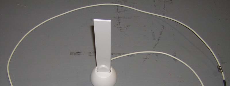
Click to zoom
Application Details
- Equipment Class
- NII - Unlicensed National Information Infrastructure TX
- Date of Grant
- Sep 26, 2004
- Application Purpose
- Original Equipment
- Date of Application
- Sep 26, 2004
- Equipment Note
- Wireless LAN Card
- Frequency Range
- 5725.00000000 - 5825.00000000
- Company
- Extreme Networks, Inc.
- Country
- United States
Documents & Files
Document Text
Text extracted from the exhibit documents filed with the FCC. Open a document above to read the original.
Users Manual
1 of 6 RoamAbout R2 Wireless Access Platform 802.11a/b/g Radio Card Quick Installation Guide This document provides the RoamAbout R2 Wireless Access Platform 802.11a/b/g radio card installation information, Radio Certification and Regulatory information. Wireless LAN and Your Health Wireless LAN products are radio devices that emit radio frequency electromagnetic energy. The level of energy emitted by a Wireless LAN device is much less than the electromagnetic energy emitted by devices like mobiles phones. Because Wireless LAN products operate within the guidelines found in radio frequency safety standards and recommendations, Enterasys believes this product is safe for use by consumers. These standards and recommendations reflect the consensus of the scientific community and result from deliberations of panels and committees of scientists who continually review and interpret the extensive research literature. Important Safety Instructions When using this product, always follow the basic safety precautions to reduce the risk of fire, electric shock and injury to persons, including the following: 1.Always install the products as described in the documentation that is included with your product. 2.Do not use the product near water, for example, near a bath tub, wash bowl, kitchen sink or laundry tub, in a wet basement or near a swimming pool. 3.Avoid using this product during an electrical storm. There may be a remote risk of electric shock from lightning. 4.Do not use this product to report a gas leak in the vicinity of the leak. Caution: Changes or modifications made to this device which are not expressly approved by the party responsible for compliance could void the user’s authority to operate the equipment. P/N 9034079-01 2 of 6 Regulatory Information You must install and use this device in strict accordance with the manufacturer’s instruction as described in the user documentation that is included with your product. Before you follow the instructions or use of this product, carefully read the contents of this document for device-specific constraints or rules that may apply in the country where you want to use this product. The user must always ensure that country and/or channel selection of Peer-to- Peer groups or Base Station Networks match the regulations of the country of operation. In some situations or environments, the use of wireless devices may be restricted by the proprietor of the building or responsible representatives of the organization. These situations may for example include: •Using the wireless equipment on board of airplanes, or •In any other environment where the risk of interference to other device or service is perceived or identified as harmful. If you are uncertain of the policy that applies to the use of wireless equipment in a specific organization or environment (e.g.airplane), you are encouraged to ask for authorization to use this device prior to turning on the equipment. The manufacturer is not responsible for any radio or television interference caused by unauthorized modification of the device, or the substitution or attachment of connecting cables and equipment other than specified by the manufacturer. The correction of interference caused by such unauthorized modification, substitution or attachment will be the responsibility of the user. The manufacturer and its authorized resellers or distributors are not liable for any damaged or violation of government regulations that may arise from failing to comply with these guidelines. Canada - Industry Canada (IC) This Class B digital apparatus meets all requirements of the Canadian Interference-Causing Equipment Regulations. cet appareil de la class B respecte toutes les exigences du Reglement sur le matereil brouiller du Canada. USA - Federal Communications Commission (FCC) This device complies with Part 15 of FCC Rules. Operation of the device is subject to the following two conditions (1) This device may not cause harmful interference, and (2) this device must accept any interference that may caused undesired operation. Exposure to Radio Frequency Radiation Caution: To comply with the FCC RF exposure compliance requirements, the following antenna installation and device operating configurations must be satisfied: For integral and external antenna configurations: The operation distance between the antenna and any other person’s body (including hands, wrists, feet and ankles) must be at least 20cm (8 inches). 3 of 6 Federal Communications Commission Notice This equipment has been tested and found to comply with the limits for a Class B digital device, pursuant to Part 15 of the FCC Rules. These limits are designed to provide reasonable protection against harmful interference in a residential installation. This equipment generated, uses, and can radiate radio frequency energy. If not installed and used in accordance with the instructions, it may cause harmful interference to radio communications. However, there is no guarantee that interference will not occur in a residential installation. If this equipment does cause harmful interference to radio or television reception, which can be determined by turning the equipment off and on, the user is encourage to try and correct the interference by one or more of following measures: •Reorient or relocate the receiving antenna. •Increase the distance between the equipment and the receiver. •Connect the equipment to an outlet on a circuit different from that to which the receiver is connected. •Consult the dealer or an experienced radio/TV technician for help. •If you have a problem with your wireless equipment, such as interference from your equipment to a Mobile Object Identification System (RF-ID), contact your authorized reseller or manufacture. Radio Approval Use the following table to determine whether you are allowed to use your wireless device in the countries listed below. You can find the radio transmitter number of your device on the identification label …
Text truncated - open the document above for the full version.
Cover Letter(s)
Hi Mike, After our review of this application we have identified the following issues, 1. Please clarify the intention of this application. Is the application for the LAN access point (Model RBTRC-MZ) with the external antenna ( RBTBH-IA) or for the RBTBH-R2W radio card with the external antenna to be used in different hosts. The latter requires a modular ( or limited modular) certification application. This application is for the LAN card only. 2. Assuming the application is for the host LAN access point as a whole, the label must be placed outside the chassis. A placement photo of this label will be needed and it should also include the compliance statements (15.19(a)(3)) on it. Please supply a revised label with placement photo. n/a 3. The antenna specification document for the external antenna, does not address the connector type on it. Please supply closer views of the MMCX antenna connector on the transmitter board and the antenna cable. Antenna connector specs attached. 4. Please supply the test setup photos. Attached. 5. Please clarify if radiated emissions tests were done with the external antenna attached/detached or both. Please also clarify which configuration (external antenna attached/detached) produces more antenna gain to the radio. Radiated emissions was tested with the range extender both on and off. The internal antennas have higher gain than the range extender. 6. Have all the modulations of 802.11a/b/g been investigated for both radiated and conducted (antenna terminal) tests for testing? Are the results in the report the worst cases recorded? Please clarify.CCK and OFDM are the available modulations for the 2.4GHz range, and only OFDM is available for the 5GHz range. All modulation types were measured and the worst case data reported. 7. Please specify the test method used for peak output power measurements at the antenna terminal during 802.11b/g configuration. (Pg 8 of the report) The output power was measured with the HP 435B power meter with the radio operating in CW mode. 8. The plot on Pg 11 of the report appears to be a duplicate of the 3rd plot on Pg 10. Please supply high band-edge (Ch11, CCK 1MBps) plot again. Updated report attached. 9. Please supply a channel allocation list from the grantee for the 802.11a configuration. The report mentions some channel changes on some of the data tables that were realized later during the test. Highest and lowest operating channel frequencies must be specified and the grantee must declare that the operation will be restricted within those channels only.Channel allocation list has been added to revised Install guide. (attached) 10. For radiated spurious emissions tests of both 802.11a and b/g configurations, have emissions been checked when the radios are transmitting on at least 3 different channels (top, middle, bottom). Please clarify. After a prescan, spurious emissions were checked only on the worst case channel. This data has been provided. 11. Have EIRP levels of the 802.11a configuration complied with the limits of 15.407(b)(1)-(4)? Please clarify. Yes. The section U-NII - Conducted Band Edges on page 22 addresses this. 12. Has the external antenna position been adjusted to maximize emissions during radiated spurious tests? Yes. This is addressed in the Test Methodology section. 13. The grantee must clarify how the device complies with 15.407(c). Description of compliance to 15.407c attached. 14. The grantee must also clarify how the device will meet the internal antenna requirement for 5.15-5.25 GHz band operation as required by 15.407(d) and how this will be ensured when marketed to the users. Description of compliance to 15.407d attached. 15. The user manual must warn the users about the indoor use requirement of the device within 5.15-5.25GHz band. Please point out the section in the manual where this was addressed. Statement placed below 802.11a channel allocation table in revised install guide. (attached) 16. The document supplied as "Manual 1" suggests portable installation conditions for RF exposure on Pg 3. These statements must be removed as they require SAR evaluations. The installation conditions with both the external and the internal antenna configurations must meet the 20cm requirement and the warning must be very clear on this in that section. SAR statements removed and 20cm warning for both integral and external antenna in revised install guide.(attached) 17. The grantee must clarify how the co-location issues will be handled within 2 radios. Pg 5 of the same document suggests that if one radio is configured for 802.11a and the other for b/g, then external antenna use is not needed. In this case the radiating structures will be closer than 20cm and co-located exposure calculations will be necessary. However if there's always and extender with one of the radios, then 20cm separation can be demonstrated. Please clarify with what kind of options (radio card - antenna combinations) is device planned to be marketed. This application is for the card only. 18. The same section of the document (Pg 5) also suggests that 2 radios of the same type can be used with an extender on one of them. For this case it must be justified how the EMC test data for one radio will be representative of both operating at the same time at the same frequency. Clarifications will be needed. Points 16, 17 and 18 will need clear instructions in the manual to avoid any confusion. This application is for the card only. 19. The RF exposure calculations must address both the "internal antenna only" and "external antenna attached" cases for both 802.11a and b/g configurations. Please revise the calculations. A note has been added to the attached MPE Calculations stating that the highest antenna gain is used in the calculation. Best Regards, Yunus Faziloglu Reviewing Engineer Curtis-Straus TCB
External Photos
REPORT: EE0676-1 FCC ID: QXO-RBTBHR2W EXHIBIT: Antenna Photos MODEL: RBTBH-IA _____________________________________________________________ _____________________________________________________________ Curtis-Straus Page 1 of 2 LLC • 527 Great Road • Littleton, MA • TEL (978) 486-8880 • FAX (978) 486-8828 REPORT: EE0676-1 FCC ID: QXO-RBTBHR2W EXHIBIT: Antenna Photos MODEL: RBTBH-IA _____________________________________________________________ _____________________________________________________________ Curtis-Straus Page 2 of 2 LLC • 527 Great Road • Littleton, MA • TEL (978) 486-8880 • FAX (978) 486-8828
External Photos
REPORT: EE0676-1 FCC ID: QXO-RBTBHR2W EXHIBIT: External Photos MODELS: RBTRC-MZ and RBTBH-R2W _____________________________________________________________ _____________________________________________________________ Curtis-Straus LLC • 527 Great Road • Littleton, MA • TEL (978) 486-8880 • FAX (978) 486-8828 Page 1 of 4 REPORT: EE0676-1 FCC ID: QXO-RBTBHR2W EXHIBIT: External Photos MODELS: RBTRC-MZ and RBTBH-R2W _____________________________________________________________ _____________________________________________________________ Curtis-Straus LLC • 527 Great Road • Littleton, MA • TEL (978) 486-8880 • FAX (978) 486-8828 Page 2 of 4 REPORT: EE0676-1 FCC ID: QXO-RBTBHR2W EXHIBIT: External Photos MODELS: RBTRC-MZ and RBTBH-R2W _____________________________________________________________ _____________________________________________________________ Curtis-Straus LLC • 527 Great Road • Littleton, MA • TEL (978) 486-8880 • FAX (978) 486-8828 Page 3 of 4 REPORT: EE0676-1 FCC ID: QXO-RBTBHR2W EXHIBIT: External Photos MODELS: RBTRC-MZ and RBTBH-R2W _____________________________________________________________ _____________________________________________________________ Curtis-Straus LLC • 527 Great Road • Littleton, MA • TEL (978) 486-8880 • FAX (978) 486-8828 Page 4 of 4
ID Label/Location Info
REPORT: EE0676-1 FCC ID: QXO-RBTBHR2W EXHIBIT: Label Placement MODEL: RBTBH-R2W _____________________________________________________________ _____________________________________________________________ Curtis-Straus LLC • 527 Great Road • Littleton, MA • TEL (978) 486-8880 • FAX (978) 486-8828 Page 1 of 1
Internal Photos
REPORT: EE0676-1 FCC ID: QXO-RBTBHR2W EXHIBIT: Internal Photos MODELS: RBTRC-MZ and RBTBH-R2W _____________________________________________________________ _____________________________________________________________ Curtis-Straus LLC • 527 Great Road • Littleton, MA • TEL (978) 486-8880 • FAX (978) 486-8828 Page 1 of 3 REPORT: EE0676-1 FCC ID: QXO-RBTBHR2W EXHIBIT: Internal Photos MODELS: RBTRC-MZ and RBTBH-R2W _____________________________________________________________ _____________________________________________________________ Curtis-Straus LLC • 527 Great Road • Littleton, MA • TEL (978) 486-8880 • FAX (978) 486-8828 Page 2 of 3 REPORT: EE0676-1 FCC ID: QXO-RBTBHR2W EXHIBIT: Internal Photos MODELS: RBTRC-MZ and RBTBH-R2W _____________________________________________________________ _____________________________________________________________ Curtis-Straus LLC • 527 Great Road • Littleton, MA • TEL (978) 486-8880 • FAX (978) 486-8828 Page 3 of 3
RF Exposure Info
FCC ID: QXO-RBTBHR2W RF Exposure Evaluation / MPE Calculation 15.247 (2.4GHz range) Page 1 of 1 RF Exposure Evaluation A calculation based on the FCC’s Evaluating Compliance with FCC Guidelines for Human Exposure to Radiofrequency Electromagnetic Fields (Edition 97-01) appears below. The highest antenna gain is used for this calculation. Maximum EIRP = 15.15dBm + 3dBi = 18.15dBm = 65.3mW The limit for General Population/Uncontrolled Exposure is S [mW/cm 2 ] = 1.0 The distance from the antenna at which this radiation level will be reached is R=SQRT(EIRP/4πS) R=SQRT( 65.3 / (4π x 1.0)) = 2.3cm RESULTS The minimum distance from the antenna at which the power density is below the limit for General Population/Uncontrolled Exposure is 2.3cm.
RF Exposure Info
FCC ID: QXO-RBTBHR2W RF Exposure Evaluation / MPE Calculation 15.407 (5GHz range) Page 1 of 1 RF Exposure Evaluation A calculation based on the FCC’s Evaluating Compliance with FCC Guidelines for Human Exposure to Radiofrequency Electromagnetic Fields (Edition 97-01) appears below. The highest antenna gain is used for this calculation. Maximum EIRP = 9.55dBm + 5dBi = 14.55dBm = 28.5mW The limit for General Population/Uncontrolled Exposure is S [mW/cm 2 ] = 1.0 The distance from the antenna at which this radiation level will be reached is R=SQRT(EIRP/4πS) R=SQRT( 28.5 / (4π x 1.0)) = 1.5cm RESULTS The minimum distance from the antenna at which the power density is below the limit for General Population/Uncontrolled Exposure is 1.5cm.
Test Report
Curtis-Straus LLC is accredited by the American Association for Laboratory Accreditation for the specific scope of accreditation under Certificate Number 1627-01. This report may contain data which is not covered by the A2LA accreditation. _____________________________________________________________ Curtis-Straus LLC • 527 Great Road • Littleton, MA • TEL (978) 486-8880 • FAX (978) 486-8828 Test Report Report No EE0676-1 Client Enterasys Networks Inc. 35 E Industrial Way Rochester, NH 03687 Phone 978-684-1009 FRN 0006-9167-61 Model RBTBH-R2W (as installed in RBTRC-MZ) FCC ID QXO-RBTBHR2W Equipment Type Unlicensed National Information Infrastructure and Digitally Modulated Equipment Code NII and DTS Results As detailed within this report Prepared by _____________________ Evan Gould – Test Engineer Authorized by __________________________ Michael Buchholz – EMC Manager Issue Date 9/14/04 Conditions of issue This Test Report is issued subject to the conditions stated in ‘terms and conditions’ section of this report. REPORT: EE0676-1 FCC ID: QXO-RBTBHR2W _____________________________________________________________ _____________________________________________________________ Curtis-Straus LLC • 527 Great Road • Littleton, MA • TEL (978) 486-8880 • FAX (978) 486-8828 Page 2 of 34 Table Of Contents Summary......................................................................................................................... 3 Test Methodology............................................................................................................ 3 Statement of Conformity.................................................................................................. 4 EUT Configurations......................................................................................................... 5 15.247 - 6dB Bandwidth.................................................................................................. 7 15.247 - Peak Output Power........................................................................................... 8 15.247 - Conducted Spurious Emissions........................................................................ 9 15.247 - Radiated Spurious Emissions......................................................................... 12 15.247 - Peak Power Spectral Density.......................................................................... 14 U-NII - 26dB Bandwidth................................................................................................. 15 U-NII - Peak Output Power............................................................................................ 16 U-NII - Peak Power Spectral Density............................................................................ 18 U-NII - Peak Excursion.................................................................................................. 20 U-NII - Conducted Band Edges..................................................................................... 22 U-NII - Radiated Spurious Emissions............................................................................ 24 U-NII - Frequency Stability............................................................................................ 26 AC Line Conducted Emission Measurements............................................................... 27 Voltage Variation........................................................................................................... 28 Test Equipment Used.................................................................................................... 29 Terms And Conditions................................................................................................... 30 A2LA Accreditation........................................................................................................ 32 REPORT: EE0676-1 FCC ID: QXO-RBTBHR2W _____________________________________________________________ _____________________________________________________________ Curtis-Straus LLC • 527 Great Road • Littleton, MA • TEL (978) 486-8880 • FAX (978) 486-8828 Page 3 of 34 Summary This test report supports an application for certification of a transmitter operating pursuant to 47 CFR 15.247 and 15.407. The product is the Enterasys RoamAbout 802.11a/b/g wireless radio card (Model RBTBH-R2W) with range extender (non- amplified external antenna, Model RBTBH-IA) as installed in the RoamAbout wireless LAN access point (Model RBTRC-MZ). The access point is populated with two of these wireless PCMCIA LAN cards which have the ability to operate in both the 802.11a range (see table below) as well as the 802.11b/g range (2400-2483.5MHz). When the access point is running with two cards, each card operates in a single range different from the other. U-NII Bands Frequency Range (GHz) Usage Limitations 5.15-5.25 Indoor use; no range extender 5.25-5.35 N/A 5.725-5.825 N/A One or the other of the cards is always populated with the range extender, which is effective in both the 2.4GHz, and 5GHz frequency ranges. The maximum directional gain of the internal antenna is 3dBi in the 2.4GHz range, and 5dBi in the 5GHz range. The directional gain of the range extender is <0.75dBi in the 2.4GHz range, and <4dBi in the 5GHz range. Test Methodology Radiated emissions testing is performed according to the procedures specified in ANSI C63.4 (2003). FCC’s “Guidance on Measurements for Digital Transmission Systems Section 15.247” and “Guidelines for Assessing Unlicensed National Information Infrastructure (U-NII) Devices – Part 15, Subpart E” were followed for testing as well. Radiated emissions were maximized by rotating the EUT (including the range extender) around three orthogonal axes as well as varying the receiving antenna’s height and polarity. The internal antenna cannot be maximized separately. Frequency range investigated: 0.15MHz – 40GHz Measurement distance: 0.15 - 30MHz Conducted 30MHz – 18GHz 3m 18 – 26.5GHz 1m 26.5 – 40GHz 0.1m AC Li…
Text truncated - open the document above for the full version.
Test Report
9/28/2004 Agere Systems (Proprietary) 1 of 2 Subject: FCC 15-407c : Automatic Discontinuation of Transmission Date: September 24, 2004 Version 1.00 Author: Jim Archibald TRANSMIT DISCONTINUATION: FCC 15.407c guidelines require that a Wireless LAN device automatically discontinue transmission when there is no information to send or if there is an operational failure. The text of the FCC requirement is as follows: IMPLEMENTATION: Figure 1 shows the block diagram of a Wireless LAN card based on the Agere chipset. This chipset includes, from left to right, the WL60040 Media Access Controller (MAC), the WL64040 Baseband Processor, the WL54040 RF transceiver and the WL54240 Power Amplifier. Agere’s solution follows the normal 802.11 MAC protocols that dictate how and when a Wireless LAN card gets access and transmits over the medium. Agere complies with the Distributed Coordination Function (DCF) architecture and the CSMA/CA (Carrier Sense Multiple Access / Collision Avoidance) scheme that permits Wireless LAN cards to access the airwaves in an orderly fashion and transmit only when the have a valid transmit frame to send. In addition to the normal MAC protocols there is also a mechanism in place whereby the WL64040 Baseband Processor is effectively muted unless the TXE (Transmit Enable) signal from the MAC is asserted. The TXE signal is shown in Figure 1 as an output going from the WL60040 MAC to the Baseband. The Baseband will not transmit unless the TXE signal from the MAC is asserted. If the TXE is de-asserted for any reason before the end of the current transmitting frame, the Baseband will abort the transmission. Hence, the control for transmission lies in the MAC via the TXE signal. This ensures that there are no random transmits. 09/28/04 Page 2 of 2 Figure 1. Block diagram of the Agere Wireless LAN system including TXE signal.
Test Report
9/28/2004 Agere Systems (Proprietary) 1 of 2 Subject: FCC 15-407d : Disabling Use of 5.15-5.25 GHz band when connecting external antenna. Date: September 23, 2004 Version 1.01 Author: Jim Archibald FEATURE DESCRIPTION: The following describes the method for disabling the use of the 802.11a/h frequencies in the 5.150 to 5.250 GHz band when an external antenna is connected. FCC specification 15.407d states that “Any U-NII device that operates in the 5.15-5.25 GHz band shall use a transmitting antenna that is an integral part of the device.” The Agere-based Wireless LAN PC- Card (reference design model 8u580) adheres to the above requirement as is described below. The model 8u580 PC-Card features an external antenna connector switch made by Aliner Enterprises (model 23-302B). The antenna connector is shown as connector J600 in Figure 1. The Aliner receptacle will accept a male connector that runs to an external 5GHz range extending antenna. When the external antenna is inserted into jack J600 then pins 1 and 2 of J600 are disconnected from each other. When this occurs, the 3.3V DC voltage provided by the DIVERSITY digital signal becomes open across J600 pins 1 and 2. This results in the signal EXTANTSEN being pulled low. The EXTANTSEN output signal runs to the PHY STATUS digital input signal on pin K2 of the Agere WL60040 Media Access Controller (MAC) IC. The firmware running in the Agere WL60040 MAC device senses the state of PHY STATUS input pin. If PHY STATUS is LOW then the logic implemented in the MAC firmware disables any 802.11 transmission in the 5.15-5.25 GHz U-NII band. 09/28/04 Page 2 of 2 Figure 1. Schematic diagram of logic used in 8u580 PC-Card to disable transmission in the 5.15- 5.25 GHz spectrum.
Test Setup Photos
REPORT: EE0676-1 FCC ID: QXO-RBTBHR2W EXHIBIT: Setup Photos MODELS: RBTRC-MZ and RBTBH-R2W _____________________________________________________________ _____________________________________________________________ Curtis-Straus LLC • 527 Great Road • Littleton, MA • TEL (978) 486-8880 • FAX (978) 486-8828 Page 1 of 3 Conducted Power Meter Measurements Conducted Analyzer Measurements REPORT: EE0676-1 FCC ID: QXO-RBTBHR2W EXHIBIT: Setup Photos MODELS: RBTRC-MZ and RBTBH-R2W _____________________________________________________________ _____________________________________________________________ Curtis-Straus LLC • 527 Great Road • Littleton, MA • TEL (978) 486-8880 • FAX (978) 486-8828 Page 2 of 3 Radiated Emissions AC Line Conducted Emissions REPORT: EE0676-1 FCC ID: QXO-RBTBHR2W EXHIBIT: Setup Photos MODELS: RBTRC-MZ and RBTBH-R2W _____________________________________________________________ _____________________________________________________________ Curtis-Straus LLC • 527 Great Road • Littleton, MA • TEL (978) 486-8880 • FAX (978) 486-8828 Page 3 of 3 Frequency Stability – Door Closed Frequency Stability – Door Open
Contact Information
Applicant
John Ballew(Senior Regulatory Compliance Manager)
Test Firm
BUREAU VERITAS CONSUMER PRODUCTS SERVICES, INC.Ozgur Ozturk
[email protected]978-486-8880
Technical Specifications
| # | Rule Parts | Frequency Range | Power Output |
|---|---|---|---|
| 2 | 15E | 5.72 GHz - 5.83 GHz | 9.00 mW |
Other Applications from Extreme Networks, Inc.
QXO-AP4000
Jul 07, 2026Access Point
Equipment Class
6SD - 15E 6 GHz Standard Power Access PointQXO-AP3020W
Jun 23, 2026Access Point
Equipment Class
DTS - Digital Transmission SystemQXO-AP5022
Jun 04, 2026Access Point
Equipment Class
DTS - Digital Transmission SystemQXO-AP5010
Apr 07, 2026Access Point
Equipment Class
6SD - 15E 6 GHz Standard Power Access PointQXO-AP5060
Feb 18, 2026Access Point
Equipment Class
NII - Unlicensed National Information Infrastructure TX