QXO-RBTSAAA802.11a/g Workgroup Bridge
Extreme Networks, Inc.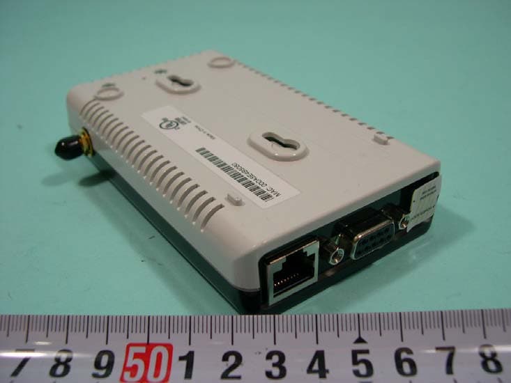
Click to zoom
Application Details
- Equipment Class
- DTS - Digital Transmission System
- Date of Grant
- Jun 30, 2005
- Application Purpose
- Original Equipment
- Date of Application
- Jun 30, 2005
- Equipment Note
- 802.11a/g Workgroup Bridge
- Frequency Range
- 2412.00000000 - 2462.00000000
- Company
- Extreme Networks, Inc.
- Country
- United States
Documents & Files
Document Text
Text extracted from the exhibit documents filed with the FCC. Open a document above to read the original.
Users Manual
7.5x9-inch cover with bleed on 4 sides RoamAbout ® Wireless Networking 11a/b/g Wireless Ethernet Adapter User Guide RBTSA-AA / RBTSA-AB P/N 9034149 ABOUT THIS GUIDE Conventions2 Related Documentation4 Accessing Online Documentation4 Product Registration and Support5 1INTRODUCTION Product Features7 Security7 Wireless Network Standards8 Network Configuration and Planning9 Example Configurations10 2INSTALLING THE ETHERNET ADAPTER Unpacking the Ethernet Adapter11 Observing Safety Precautions12 Deciding Where to Place the Ethernet Adapter13 Wall-Mounting the Ethernet Adapter13 Connecting the Ethernet Adapter15 Connecting to a Serial Device15 Connecting to an Ethernet Device16 About the Client List16 Connecting to a Hub17 Connecting to a Network Printer17 Connecting to a Computer18 Checking the LED Indicators18 Attaching An External Antenna20 Determining if you Need to Configure the Ethernet Adapter20 Using the Enterasys Networks Installation CD23 CONTENTS 3CONFIGURING THEETHERNET ADAPTER Using Secure Web Server Connection25 Using the Enterasys Networks Wireless Infrastructure Device Manager26 Using the Configuration Management System29 Clearing and Applying System Configuration Settings30 Changing System Properties31 Setting IP Network Properties32 Setting Wireless Network Properties33 Manually Selecting Radio Channels35 Setting Up an Ad-Hoc Network35 Changing Wireless Security Settings36 Changing RADIUS Settings39 Changing SNMP Settings40 Using the Access Control List40 Serial Port42 Resetting the Ethernet Adapter45 Restoring the Ethernet Adapter to Factory Defaults45 Upgrading the System46 Changing the Administration Login Name and Password47 Backing up a Configuration48 Restoring a Configuration48 Logging Out48 Clearing the Ethernet Client List49 Viewing Connection Status49 Viewing System Summary50 4TROUBLESHOOTING Diagnosing Problems51 Disconnecting the Ethernet Adapter53 Uninstalling Software and Documentation54 Upgrading Ethernet Adapter Firmware54 AOBTAINING SUPPORT FOR YOUR ENTERASYS NETWORKS P RODUCT Getting Help55 END USER LICENSE AGREEMENT REGULATORY INFORMATION ABOUT THIS GUIDE This guide provides all the information you need to install and use the Enterasys Networks 11a/b/g Wireless Ethernet Adapter in its default state. The guide is intended for use by IT managers and experienced network installation and administration professionals who have a basic knowledge of current networking concepts. If the information in the release notes that are shipped with your product differ from the information in this guide, follow the instructions in the release notes. Most user guides and release notes are available in Adobe Acrobat Reader Portable Document Format (PDF) or HTML on the Enterasys Networks World Wide Web site: http://www.enterasys.com/products/wireless/ 2ABOUT THIS GUIDE ConventionsTable 1 and Table 2 list conventions that are used throughout this guide. Ta b l e 1 Notice Icons IconNotice TypeDescription Information noteInformation that describes important features or instructions. CautionInformation that alerts you to potential loss of data or potential damage to an application, system, or device. Achtung:Verweist auf wichtige Informationen zum Schutz gegen Beschadigungen. WarningInformation that alerts you to potential personal injury. WarnungWarnung vor samtlichen Handlungen, die zu Verletzung von Personen oder Todesfallen - hervorgerufen durch elektrische Spannung - fuhren konnen! Ta b l e 2 Text Conventions ConventionDescription Screen displaysThis typeface represents information as it appears on the screen. SyntaxThe word “syntax” means that you must evaluate the syntax provided and then supply the appropriate values for the placeholders that appear in angle brackets. Example: To change your password, use the following syntax: system password <password> In this example, you must supply a password for <password>. The words “enter” and “type” When you see the word “enter” in this guide, you must type something, and then press Return or Enter. Do not press Return or Enter when an instruction simply says “type.” Keyboard key namesIf you must press two or more keys simultaneously, the key names are linked with a plus sign (+). Example: Press Ctrl+Alt+Del Conventions3 Words in italicsItalics are used to: ■Emphasize a point. ■Denote a new term at the place where it is defined in the text. ■Identify menu names, menu commands, and software button names. Examples: From the Help menu, select Contents. Click OK. Ta b l e 2 Text Conventions (continued) ConventionDescription 4ABOUT THIS GUIDE Related Documentation In addition to this guide, each Ethernet Adapter documentation set includes the following: ■Quick Start Guide—printed guide that describes basic installation. ■Online Help—product help systems that describe how to use the Configuration Management System and Enterasys Networks Wireless Infrastructure Device Manager. ■Release Note—printed note that describes important product information. ■README.TXT file—text file located on the Enterasys Networks Installation CD that describes last-minute product information. Accessing Online Documentation The CD supplied with your Ethernet Adapter contains the following online documentation: ■Enterasys Networks 11a/b/g Wireless Ethernet Adapter User Guide ■Enterasys Networks Wireless Infrastructure Device Manager Online Help ■Enterasys Networks 11a/b/g Wireless Ethernet Adapter Configuration Management System Online Help To access the online documentation from the CD: 1Insert the Enterasys Networks Installation CD supplied with your Ethernet Adapter in the CD-ROM drive. The setup menu appears. If it does not appear, you can start the setup menu from the Windows Start menu. For example: Start > Run > d:launch.exe. 2In the menu, click View the Documentation to view the Ethernet Adapter User Guide. To view the online help, install and launch the Wireless Infrastructure Device Manager or Configuration Management System. See Chapter 3 for instruction…
Text truncated - open the document above for the full version.
External Photos
SPORTON International Inc. PAGE NUMBER : A1 OF A2 TEL : 886-2-2696-2468 ISSUED DATE : June 02, 2005 FAX : 886-2-2696-2255 APPENDIX A. Photographs of EUT 453118-02 453118-02 SPORTON International Inc. PAGE NUMBER : A2 OF A2 TEL : 886-2-2696-2468 ISSUED DATE : June 02, 2005 FAX : 886-2-2696-2255 453118-02
ID Label/Location Info
FEDERAL COMMUNICATIONS COMMISSION This device complies with Part 15 of the FCC Rules. Operation is subject to the following two conditions:(1) this device may not cause harmful interference, and (2) this device must accept any interference received, including interference that may cause undesired operation.
ID Label/Location Info
SPORTON International Inc. PAGE NUMBER : A1 OF A1 TEL : 886-2-2696-2468 ISSUED DATE : June 02, 2005 FAX : 886-2-2696-2255 FCC ID: QXO-RBTSAAA Label Location 453118-02
Internal Photos
SPORTON International Inc. PAGE NUMBER : A1 OF A6 TEL : 886-2-2696-2468 ISSUED DATE : June 02, 2005 FAX : 886-2-2696-2255 APPENDIX A. Photographs of EUT 453118-02 453118-02 SPORTON International Inc. PAGE NUMBER : A2 OF A6 TEL : 886-2-2696-2468 ISSUED DATE : June 02, 2005 FAX : 886-2-2696-2255 453118-02 453118-02 SPORTON International Inc. PAGE NUMBER : A3 OF A6 TEL : 886-2-2696-2468 ISSUED DATE : June 02, 2005 FAX : 886-2-2696-2255 453118-02 453118-02 SPORTON International Inc. PAGE NUMBER : A4 OF A6 TEL : 886-2-2696-2468 ISSUED DATE : June 02, 2005 FAX : 886-2-2696-2255 453118-02 453118-02 SPORTON International Inc. PAGE NUMBER : A5 OF A6 TEL : 886-2-2696-2468 ISSUED DATE : June 02, 2005 FAX : 886-2-2696-2255 453118-02 453118-02 SPORTON International Inc. PAGE NUMBER : A6 OF A6 TEL : 886-2-2696-2468 ISSUED DATE : June 02, 2005 FAX : 886-2-2696-2255 453118-02
RF Exposure Info
FCC ID: QXO-RBTSAAA Issued on May 30, 2005 Report No.: FR453118-02 SPORTON International Inc. Page No. : 55 of 61 TEL : 886-2-2696-2468 Issued Date : May 30, 2005 FAX : 886-2-2696-2255 5.8. RF Exposure 5.8.1. Limit For Maximum Permissible Exposure (MPE) This product can be classified as mobile device, so the 20cm separation distance warning is required. In this section, the power density at 20cm location is calculated to examine if it is lower than the limit. (A) Limits for Occupational / Controlled Exposure Frequency Range (MHz) Electric Field Strength (E) (V/m) Magnetic Field Strength (H) (A/m) Power Density (S) (mW/ cm²) Averaging Time |E|²,|H|² or S (minutes) 0.3-3.0 614 1.63 (100)* 6 3.0-30 1842 / f 4.89 / f (900 / f)* 6 30-300 61.4 0.163 1.0 6 300-1500 F/300 6 1500-100,000 5 6 (B) Limits for General Population / Uncontrolled Exposure Frequency Range (MHz) Electric Field Strength (E) (V/m) Magnetic Field Strength (H) (A/m) Power Density (S) (mW/cm²) Averaging Time |E|²,|H|² or S ( minutes ) 0.3-1.34 614 1.63 (100)* 30 1.34-30 824/f 2.19/f (180/f)* 30 30-300 27.5 0.073 0.2 30 300-1500 F/1500 30 1500-100,000 1.0 30 F = frequency in MHz *Plane-wave equivalent power density FCC ID: QXO-RBTSAAA Issued on May 30, 2005 Report No.: FR453118-02 SPORTON International Inc. Page No. : 56 of 61 TEL : 886-2-2696-2468 Issued Date : May 30, 2005 FAX : 886-2-2696-2255 5.8.2. MPE Calculation Method E (V/m) = d GP××30 Power Density: Pd (mW/cm²) = 377 2 E E = Electric field (V/m) P = Peak RF output power (mW) G = EUT Antenna numeric gain (numeric) d = Separation distance between radiator and human body (m) The formula can be changed to Pd = 2 377 30 d GP × ×× From the peak EUT RF output power, the minimum mobile separation distance, d=20cm, as well as the gain of the used antenna, the RF power density can be obtained. 5.8.3. Calculated Result and Limit Modulation Type: CCK Test Engineer: Bunny Yao Mode 1 Channel No. Antenna Gain (dBi) Antenna Gain (numeric) Peak Output Power (dBm) Peak Output Power ( mW ) Power Density (S) (mW/cm²) Limit of Power Density (S) (mW/cm²) Channel 1 2.5 1.78 20.52 112.7197 0.0399 1 Channel 6 2.5 1.78 21.02 126.4736 0.0448 1 Channel 11 2.5 1.78 20.65 116.1449 0.0411 1 FCC ID: QXO-RBTSAAA Issued on May 30, 2005 Report No.: FR453118-02 SPORTON International Inc. Page No. : 57 of 61 TEL : 886-2-2696-2468 Issued Date : May 30, 2005 FAX : 886-2-2696-2255 Mode 2 Channel No. Antenna Gain (dBi) Antenna Gain (numeric) Peak Output Power (dBm) Peak Output Power ( mW ) Power Density (S) (mW/cm²) Limit of Power Density (S) (mW/cm²) Channel 1 5.15 3.27 20.52 112.7197 0.0734 1 Channel 6 5.15 3.27 21.02 126.4736 0.0824 1 Channel 11 5.15 3.27 20.65 116.1449 0.0757 1 Mode 3 Channel No. Antenna Gain (dBi) Antenna Gain (numeric) Peak Output Power (dBm) Peak Output Power ( mW ) Power Density (S) (mW/cm²) Limit of Power Density (S) (mW/cm²) Channel 1 1.58 1.44 20.52 112.7197 0.0324 1 Channel 6 1.58 1.44 21.02 126.4736 0.0364 1 Channel 11 1.58 1.44 20.65 116.1449 0.0333 1 *From the calculated result shown in above table, the power density is lower than limit at location 20cm far away. FCC ID: QXO-RBTSAAA Issued on May 30, 2005 Report No.: FR453118-02 SPORTON International Inc. Page No. : 58 of 61 TEL : 886-2-2696-2468 Issued Date : May 30, 2005 FAX : 886-2-2696-2255 Modulation Type: OFDM Test Engineer: Bunny Yao Mode 1 Channel No. Antenna Gain (dBi) Antenna Gain (numeric) Peak Output Power (dBm) Peak Output Power ( mW ) Power Density (S) (mW/cm²) Limit of Power Density (S) (mW/cm²) Channel 1 2.5 1.78 21.85 153.1087 0.0542 1 Channel 6 2.5 1.78 22.32 170.6082 0.0604 1 Channel 11 2.5 1.78 22.05 160.3245 0.0567 1 Mode 2 Channel No. Antenna Gain (dBi) Antenna Gain (numeric) Peak Output Power (dBm) Peak Output Power ( mW ) Power Density (S) (mW/cm²) Limit of Power Density (S) (mW/cm²) Channel 1 5.15 3.27 21.85 153.1087 0.0998 1 Channel 6 5.15 3.27 22.32 170.6082 0.1112 1 Channel 11 5.15 3.27 22.05 160.3245 0.1045 1 FCC ID: QXO-RBTSAAA Issued on May 30, 2005 Report No.: FR453118-02 SPORTON International Inc. Page No. : 59 of 61 TEL : 886-2-2696-2468 Issued Date : May 30, 2005 FAX : 886-2-2696-2255 Mode 3 Channel No. Antenna Gain (dBi) Antenna Gain (numeric) Peak Output Power (dBm) Peak Output Power ( mW ) Power Density (S) (mW/cm²) Limit of Power Density (S) (mW/cm²) Channel 1 1.58 1.44 21.85 153.1087 0.0440 1 Channel 6 1.58 1.44 22.32 170.6082 0.0490 1 Channel 11 1.58 1.44 22.05 160.3245 0.0459 1 *From the calculated result shown in above table, the power density is lower than limit at location 20cm far away.
Test Report
FCC ID: QXO-RBTSAAA Issued on May 30, 2005 Report No.: FR453118-02 SPORTON International Inc. TEL : 886-2-2696-2468 FAX : 886-2-2696-2255 FCC TEST REPORT CATEGORY : Module for Professional Use Mobile Host PRODUCT NAME : 802.11a/g Workgroup Bridge FCC ID. : QXO-RBTSAAA FILING TYPE : Certification BRAND NAME : Enterasys MODEL NAME : WP300A-E2, RBTSA-AA, RBTSA-AB APPLICANT : Enterasys Networks, Inc. 50 Minuteman Road, Andover, MA 01810, USA MANUFACTURER : DONGGUAN G-COM COMPUTER CO., LTD. 1 st Row Yin Shan Rd., Yin Hwu Industrial Area, Qingxi Town, Dong Guan City, Guang Dong, China ISSUED BY : SPORTON INTERNATIONAL INC. 6F, No. 106, Sec. 1, Hsin Tai Wu Rd., His Chih, Taipei Hsien, Taiwan, R.O.C. Statements: Only the test result of 802.11b/g part is shown in this test report. The test result in this report refers exclusively to the presented test model / sample. Without written approval of SPORTON International Inc., the test report shall not be reproduced except in full. Certificate or Test Report could not be used by the applicant to claim the product endorsement by CNLA, NVLAP or any agency of U.S. government. The test equipment used to perform the test are calibrated and traceable to NML/ROC or NIST/USA. Lab Code: 200079-0 FCC ID: QXO-RBTSAAA Issued on May 30, 2005 Report No.: FR453118-02 SPORTON International Inc. Page No. : i TEL : 886-2-2696-2468 Issued Date : May 30, 2005 FAX : 886-2-2696-2255 Table of Contents History of this test report....................................................................................................................................ii 1. General Description of Equipment under Test.............................................................................................1 1.1. Applicant..........................................................................................................................................................................................1 1.2. Manufacturer ...................................................................................................................................................................................1 1.3. Basic Description of Equipment under Test ....................................................................................................................................1 1.4. Features of Equipment under Test ( 802.11b/g part ) .....................................................................................................................1 1.5. Antenna Description ........................................................................................................................................................................2 1.6. Table for Carrier Frequencies ( 802.11b/g part ).............................................................................................................................2 2. Test Configuration of the Equipment under Test.........................................................................................3 2.1. Description of the Test ....................................................................................................................................................................3 2.2. Frequency Range Investigated .......................................................................................................................................................3 2.3. Description of Test Supporting Units...............................................................................................................................................3 2.4. Connection Diagram of Test System ..............................................................................................................................................4 2.5. Test Software ..................................................................................................................................................................................4 3. Test Location and Standards .........................................................................................................................5 3.1. Test Location...................................................................................................................................................................................5 3.2. Test Conditions ...............................................................................................................................................................................5 3.3. Standards for Methods of Measurement .........................................................................................................................................5 3.4. DoC Statement................................................................................................................................................................................5 4. List of Measurements......................................................................................................................................6 4.1. Summary of the Test Results ..........................................................................................................................................................6 5. Test Result .......................................................................................................................................................7 5.1. Test of 6dB Spectrum Bandwidth....................................................................................................................................................7 5.2. Test of Maximum Peak Output Power ..........................................................................................................................................12 5.3. Test of Peak Power Spectral Density............................................................................................................................................14 5.4. Test of Band Edges Emission ..........…
Text truncated - open the document above for the full version.
Test Setup Photos
FRONT VIEW REAR VIEW Mode 1 FRONT VIEW REAR VIEW Mode 2 FRONT VIEW REAR VIEW Mode 3 FRONT VIEW REAR VIEW
Contact Information
Applicant
John Ballew(Senior Regulatory Compliance Manager)
Technical Contact
Sporton International Inc.Wayne Hsu
[email protected]886-3-327-3456
No. 52, Hwa Ya 1st Rd., Kwei-Shan Hsiang, · TaoYuan Hsien · Taiwan
Test Firm
Sporton International Inc.Kathy Lin
Technical Specifications
| # | Rule Parts | Frequency Range | Power Output |
|---|---|---|---|
| 1 | 15C | 2.41 GHz - 2.46 GHz | 170.61 mW |
Other Applications from Extreme Networks, Inc.
QXO-AP4000
Jul 07, 2026Access Point
Equipment Class
6SD - 15E 6 GHz Standard Power Access PointQXO-AP3020W
Jun 23, 2026Access Point
Equipment Class
DTS - Digital Transmission SystemQXO-AP5022
Jun 04, 2026Access Point
Equipment Class
DTS - Digital Transmission SystemQXO-AP5010
Apr 07, 2026Access Point
Equipment Class
6SD - 15E 6 GHz Standard Power Access PointQXO-AP5060
Feb 18, 2026Access Point
Equipment Class
NII - Unlicensed National Information Infrastructure TX