QZIMBH2BT01Bluetooth CF Card
Fujitsu Media Devices Limited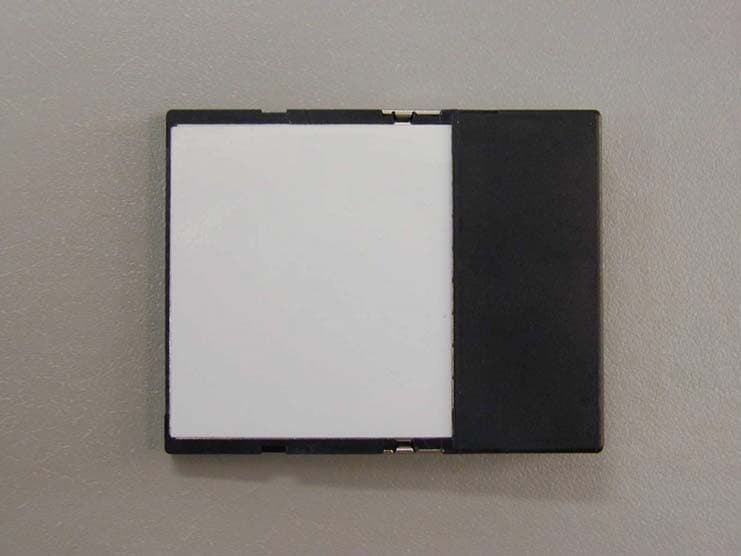
Click to zoom
Application Details
- Equipment Class
- DSS - Part 15 Spread Spectrum Transmitter
- Date of Grant
- Apr 13, 2003
- Application Purpose
- Original Equipment
- Date of Application
- Apr 13, 2003
- Equipment Note
- Bluetooth CF Card
- Frequency Range
- 2402.00000000 - 2480.00000000
- Country
- Japan
Documents & Files
Document Text
Text extracted from the exhibit documents filed with the FCC. Open a document above to read the original.
Users Manual
Copyright © FUJITSU MEDIA DEVICES LIMITED 2003 Bluetooth CF Card MBH2BT01 User’s Guide February 14, 2003 FUJITSU MEDIA DEVICES LIMITED Copyright © FUJITSU MEDIA DEVICES LIMITED 2003 SAFETY INSTRUCTIONS For safe use of your MBH2BT01, always follow the instructions below. This guide uses graphical symbols to highlight instructions that you must follow to avoid personal injury or damage to property when using the MBH2BT01. Before reading this guide, read the following explanations carefully to fully understand the meanings of these symbols. ELECTRICAL PRECAUTIONS · This device could malfunction in the event of a voltage sag or momentary drop in voltage because of electrical disturbance. To protect your computer against voltage sag, use of an uninterruptible power supply (UPS) is recommended. · The frequency band used for this device is the same as for some types of industrial, scientific, and medical equipment, including microwave ovens, as well as on-premises radio stations, (e.g., radio stations installed in production lines), and other application-specific low-output radio stations. Before using this device, make sure there is no on-premises radio station near the device. · In the event this device causes radio frequency interference to an on-premises radio station for identification of mobile units, immediately change the frequency used or break off connection, and consult FM Information Service about preventive measures against radio frequency interference (for example, installation of partitions). CAUTIONS · Remove the MBH2BT01 from your computer or turn off your computer in a hospital or near a medical electronic system. Do not bring your computer with the MBH2BT01 connected in an operating room, otherwise radio waves transmitted by the MBH2BT01 could affect medial electric systems. · Keep your computer at least 8.5 inches (22 cm) away from a pacemaker, otherwise radio waves could prevent it from functioning properly. · Remove the MBH2BT01 from your computer or turn off your computer on an airplane or when driving. · Remove the MBH2BT01 from your computer where it can be exposed to flammable gas, otherwise it could cause an explosion or fire. · Do not use the MBH2BT01 near an automatic door or fire alarm, otherwise radio waves transmitted by the MBH2BT01 could affect its automatic control unit. · Never disassemble, repair, or modify the MBH2BT01. Touching internal components could cause you to get an electric shock. · Do not place vessels containing liquid near your computer. Liquid could cause an electric shock if it gets in the computer. · When inserting the MBH2BT01 in a card slot or ejecting the card from it, don't put your finger into the slot. · The MBH2BT01 may heat up after being used for a long period. Do not remove it from your computer immediately after use. · Do not bring magnetic cards, including floppy disks and credit cards, close to the MBH2BT01, otherwise data recorded on them could be lost. · Do not use or store the MBH2BT01 where it will be exposed to shock or vibration. · Do not place the MBH2BT01 where it will be exposed to extreme heat or cold, or where the temperature can greatly vary. Registered Trademark(s)®, Trademark(s)™ and Service Mark(s) SM BLUETOOTH is a trademark owned by Bluetooth SIG, Inc., U.S.A. and licensed to Fujitsu. Microsoft, Windows, Outlook, ActiveSync, and the Windows CE logo (graphic only) are either registered trademarks or trademarks of Microsoft Corporation in the United States and/or other countries. BTW-CE is licensed from WIDCOMM, Inc. to Fujitsu Media Devices Limited. Other brand and product names may be registered trademarks, service marks, or trademarks of their respective holders. We cannot guarantee the accuracy of the contents of this document. We disclaim liability for errors, omissions or future changes. Copyright © FUJITSU MEDIA DEVICES LIMITED 2003 FCC Part 15 Subpart B Class B NOTICE This equipment has been tested and found to comply with the limits for a Class B digital device, pursuant to part 15 of the FCC Rules. These limits are designed to provide reasonable protection against harmful interference in a residential installation. This equipment generates, uses and can radiate radio frequency energy and, if not installed and used in accordance with the instructions, may cause harmful interference to radio communications. However, there is no guarantee that interference will not occur in a particular installation. If this equipment does cause harmful interference to radio or television reception, which can be determined by turning the equipment off and on, the user is encouraged to try to correct the interference by one or more of the following measures: -Reorient or relocate the receiving antenna -Increase the separation between the equipment and receiver. -Connect the equipment into an outlet on a circuit different from that to which the receiver is connected. -Consult the dealer or an experienced radio/TV technician for help. FCC WARNING Changes or modifications not expressly approved by the party responsible for compliance could void the user's authority to operate the equipment. This transmitter must not be co-located or operating in conjunction with any other transmitter or antenna. This device complies with part 15 of the FCC Rules. Operation is subject to the following two conditions: (1) this device may not cause harmful interference, and (2) this device must accept any interference received, including interference that may cause undesired operation. MBH2BT01 User’s Guide Table of Contents Copyright © FUJITSU MEDIA DEVICES LIMITED 2003 Table of Contents 1 Introduction To Bluetooth Software (BTW-CE) for MBH2BT01 ..................................................................1 1.1 BLUETOOTH ICON ..............................................................................................................................1 1.2 INSTALLATION............................................................................…
Text truncated - open the document above for the full version.
Cover Letter(s)
FUJITSU MEDIA DEVICES LIMITED Shin-Yokohama Square Bldg., 12F, Shin-Yokohama 2-3-12, Kohoku-ku, Yokohama, Kanagawa 222-0033, Japan Tel: (81)45-476-4273 Fax: (81)-45-476-4265 Request for Confidentiality Date: April 2, 2003 American Telecommunications Certification Body, Inc. 6731 Whittier Avenue Suite C110 McLean, VA 22101 RE: Certification Application FCC ID: QZIMBH2BT01 Please be advised that the following information is to be held confidential and behalf of, Fujitsu Media Devices Limited: Block Diagram Schematics The application contains technical information which Fujitsu Media Devices Limited, deems to be trade secrets and proprietary. If made public, the information might be used to the disadvantage of the applicant in the market place. Thank you for your attention to this matter. Sincerely, Masayoshi Hanano Director Design & Development Dept. 1, Mobile Devices Division
Cover Letter(s)
FUJITSU MEDIA DEVICES LIMITED Shin-Yokohama Square Bldg., 12F, Shin-Yokohama 2-3-12, Kohoku-ku, Yokohama, Kanagawa 222-0033, Japan Tel: (81)45-476-4273 Fax: (81)-45-476-4265 April 2, 2003 FCC ID : QZIMBH2BT01 Model : MBH2BT01 Applicant : Fujitsu Media Devices Limited Request for Modular Approval The modular transmitter (Model: MBH2BT01) is designed by Fujitsu Media Devices Limited. The modular transmitter complies the module basic requirement (Item 1 to 8) in FCC Public Notice: Part 15 Unlicensed Modular Transmitter Approval as indicated below: [Module basic requirement] (1) Have its own RF shielding.: This modular transmitter has it own RF shielding. Whole part of this module is shielded by cover. Please find attached Photo A1. (2) The modular transmitter must have buffered modulation/data inputs.: Data input to Modular transmitter is controlled as not generating excessive data speed and abnormal modulation. (3) The modular transmitter must have its own power supply regulation.: The module can regulate Power Supply by itself. (See Schematic) (4) The modular transmitter must comply with the antenna requirements of Section 15.203 and 15.204(c).: The antenna of this equipment is installed into the chassis. So, it is impossible for users to disconnect it. Accordingly, it is complied. (5) The modular transmitter must be tested in a stand alone.: The modular transmitter has been performed the testing as a stand alone and then confirmed the compliance. Please refer to the Test report (No. 23FE0027-YK-1) (6) The modular transmitter must be labeled with its own FCC ID number, and, if the FCC ID is not visible when The module is installed inside another device, then the outside of the device into which the module is installed must also display a label referring to the enclosed module.: This modular transmitter is complied with this requirement. Please refer to the file of Label drawing and location. (7) The modular transmitter must comply with any specific rule or operating requirements applicable to the transmitter and the manufacturer must provide adequate instructions along with the module to explain any such requirements.: The necessary explanation to be complied with this requirement is contained in the manual. (8) The modular transmitter must comply with any applicable RF exposure requirements.: The modular transmitter complies with FCC radiation exposure requirement specified in the FCC Rules 15.247(b)(4). Please refer to the RF exposure statement. Masayoshi Hanano Director Design & Development Dept. 1, Mobile Devices Division FUJITSU MEDIA DEVICES LIMITED Shin-Yokohama Square Bldg., 12F, Shin-Yokohama 2-3-12, Kohoku-ku, Yokohama, Kanagawa 222-0033, Japan Tel: (81)45-476-4273 Fax: (81)-45-476-4265 A1:Photographs of Bluetooth CF Card RF Shielding (Cover shield) Top Bottom Bluetooth CF Card Top Bottom Bluetooth CF Card (Cover Shielding off)
Cover Letter(s)
FUJITSU MEDIA DEVICES LIMITED Shin-Yokohama Square Bldg., 12F, Shin-Yokohama 2-3-12, Kohoku-ku, Yokohama, Kanagawa 222-0033, Japan Tel: (81)45-476-4273 Fax: (81)-45-476-4265 Letter Of Agency Date: April 2, 2003 American Telecommunications Certification Body, Inc. 6731 Whittier Avenue Suite C110 McLean, VA 22101 To Whom It May Concern: Please be advised that Fujitsu Media Devices Limited, authorizes A-Pex International Co., Ltd. to act on our behalf, until otherwise notified, for applications submitted to American Telecommunications Certification Body, Inc. (ATCB). We certify that we are not subject to denial of federal benefits, that includes FCC benefits, pursuant to Section 5301 of the Anti-Drug Abuse ACT of 1988, U.S.C. 862. Further, no party, as defined in 47 CFR 1.2002(b), to the application is subject to denial of federal benefits, that includes FCC benefits. Thank you for your attention to this matter. Sincerely, Masayoshi Hanano Director Design & Development Dept. 1, Mobile Devices Division
Cover Letter(s)
American Telecommunications Certification Body Inc. 6731 Whittier Ave, McLean, VA 22101 April 9, 2003 RE: FCC ID: QZIMBH2BT01 Attention: Keijiro Kumagai / Toyokazu Imamura I have a few comments on this Application. 1. The report states that this is a professionally installed device (see page 4 or the report). The manual clearly states otherwise. The report states that the antenna is a standard antenna connector. The photos show the device as assembled has no antenna connector (indicating integral antenna). Please correct your documentation to appropriately identify the antenna type and please remove and correct your reference to a professionally installed device (CF cards are not professionally installed devices). 2. Please provide a photo of the antenna that connects to the antenna connector on the card and please show how it is integral or non-standard connection. Please remember that CF cards are not professionally installed and thus can not meet the antenna exception for standard connectors. You must show how the antenna is integral or how it uses a non standard connection. Dennis Ward mailto:[email protected] The items indicated above must be submitted before processing can continue on the above referenced application. Failure to provide the requested information may result in application termination. Correspondence should be considered part of the permanent submission and may be viewed from the Internet after a Grant of Equipment Authorization is issued. Please do not respond to this correspondence using the email reply button. In order for your response to be processed expeditiously, you must submit your documents through the AmericanTCB.com website. Also, please note that partial responses increase processing time and should not be submitted. Any questions about the content of this correspondence should be directed to the sender.
Cover Letter(s)
Subject: RE: New project: Bluetooth CF Card(FCC ID:QZIMBH2BT01) Date: Fri, 11 Apr 2003 10:43:20 +0900 From: [email protected] To: [email protected] CC: [email protected], [email protected] Dear Dennis, Thank you very much for your speedy response to our submission. Statements below are reply to your comments. Please confirm. Reply to your comment No.1: As you stated on your email, professional installation is inappropriate for this device. Also Antenna Connector of this device is not a standard one. We made mistake on the report. So please find attached "Revised Test Report[23FE0027-YK].pdf". About Antenna Type, please find "MBH2BT01 Components.pdf" and "MBH2BT01 BOM.pdf" Reply to your comment No.2: Antenna is placed on circuit board of module. Please refer to submitted photo and block diagram. I appreciate for your issuance of grant soon. Please let us know if you have any other remarks. Best Regards, Keijiro Kumagai A-Pex International Co.Ltd. 4383-326 Asama-cho Ise-shi Mie-ken 516-0021 JAPAN TEL +81-596-24-8116 FAX +81-596-24-8124 E-mail: [email protected] 2003/04/10 3:52:14 $B!" (B"dward" $B$5$s$O!V (BRE: New project: Bluetooth CF Card(FCC ID:QZIMBH2BT01) $B!W$G=q$-$^$7$? (B > Hi Keijiro > Please see comments > Thanks > Dennis > > -----Original Message----- > From: [email protected] [mailto:[email protected] ] > Sent: Wednesday, April 09, 2003 12:11 AM > To: [email protected]; [email protected] > Cc: [email protected] > Subject: New project: Bluetooth CF Card(FCC ID:QZIMBH2BT01) > > > > Dear Dennis, > > Today I submitted application documents of FUJITSU MEDIA DEVICES LIMITED, > Bluetooth CF Card(FCC ID: QZIMBH2BT01). Please verify and let us know if > there is any problem. > > Also please provide us invoice for this project. > > I appreciate for your cooperation. > > Best Regards, > > Keijiro Kumagai > A-Pex International Co.Ltd. > 4383-326 Asama-cho Ise-shi > Mie-ken 516-0021 JAPAN > TEL +81-596-24-8116 > FAX +81-596-24-8124 > E-mail: [email protected] > > - 4-9-03 QZIMBH2BT01_ATCB Comments.pdf (See attached file: Revised Test Report[23FE0027-YK].pdf)(See attached file: MBH2BT01Components.pdf)(See attached file: MBH2BT01BOM.pdf) Revised Test Report[23FE0027-YK].pdf Name: Revised Test Report[23FE0027-YK].pdf Type: Acrobat (application/pdf) Encoding: base64 MBH2BT01Components.pdf Name: MBH2BT01Components.pdf Type: Acrobat (application/pdf) Encoding: base64 MBH2BT01BOM.pdf Name: MBH2BT01BOM.pdf Type: Acrobat (application/pdf) Encoding: base64
External Photos
External Photo FUJITSU MEDIA DEVICES LIMITED Model: MBH2BT01 FCC ID: QZIMBH2BT01 To p Vi e w Bottom View External Photo FUJITSU MEDIA DEVICES LIMITED Model: MBH2BT01 FCC ID: QZIMBH2BT01 Left Side View Right Side View External Photo FUJITSU MEDIA DEVICES LIMITED Model: MBH2BT01 FCC ID: QZIMBH2BT01 Front View Rear View
Internal Photos
Internal Photo FUJITSU MEDIA DEVICES LIMITED Model: MBH2BT01 FCC ID: QZIMBH2BT01 To p Vi e w Bottom View
Operational Description
CONFIDENTIAL Copyright © FUJITSU MEDIA DEVICES LIMITED 2003 - 1 - MBH2BT01 SPEC SHEET Revision 0.2E Feb 14, 2003 FUJITSU MEDIA DEVICES LIMITED All specifications are preliminary which may be changed without any prior notice CONFIDENTIAL Copyright © FUJITSU MEDIA DEVICES LIMITED 2003 - 2 - 1. APPLICATION This document is applied for MBH2BT01 CF Card implemented Bluetooth™ specification. 2. FEATURES MBH2BT01 is the Bluetooth™ CF Card included RF, Baseband, Link Manager and HCI. MBH2BT01 enables wireless communication at 2.4GHz (ISM band). ComapctFlash Card TYPE I Extended Power Class 2 Built-in antenna Support both 3.3V and 5V operation Bluetooth qualified 3. BLOCK DIAGRAM Power Amp Low Noise Amp EEPROM 2k or 4kbit Serial CF Card Interface Connector 50pin CF Card Interface ASIC Bluetooth Controller CSR BC01B Flash memory EEPROM Low Noise Amp BPF Antenna SW Crystal Antenna Crystal CONFIDENTIAL Copyright © FUJITSU MEDIA DEVICES LIMITED 2003 - 3 - 4. ELECTRICAL CHARACTERISTICS 4-1. FUNCTIONS 4-1-1. CF Interface Part CompactFlash Specification Revision 1.4 compliant Including Card Information Structure (CIS) Supply voltage 5V or 3.3V 16550A UART compatible register (Supported 921.6kbps using the special driver software) 4-1-2. Bluetooth Part Bluetooth Specification Version 1.1 compliant Carrier Frequency 2400 to 2483.5 MHz (ISM radio band) Modulation 0.5 BT Gaussian-filtered 2FSK at 1Msymbol/s Modulation index: 0.25 to 0.35 Symbol Rate 1Mbps Transmission Speed Asymmetrical : Forward 723.2kbps (Max), Reverse 57.6kbps Symmetrical : 433.9kbps (Max) Channel 79 Transmit Power Power Class 2 Built-in antenna Ceramic chip antenna CONFIDENTIAL Copyright © FUJITSU MEDIA DEVICES LIMITED 2003 - 4 - 4-2. ELECTRICAL CHARACTERISTICS 4-2-1. Absolute Maximum Ratings Parameter SymbolConditionValue Unit Supply Voltage Vcc 6.5 V Input Voltage Vin 50Pin GND-0.5 ~ Vcc+0.5 V Power Consumption Pd 700 mW Operating Temperature Topr 0 ~ +60 ºC Storage Temperature Tstg -20 ~ +75 ºC 4-2-2. Recommendable Operating Condition Parameter SymbolCondition Min Typ Max Unit 4.5 5.0 5.5 V Supply Voltage Vcc 3.135 3.3 3.465 V Operating Temperature Topr +10 +40 ºC 4-2-3. Power Consumption Vcc=3.3V, Ta=25 ±2ºC Parameter Symbol Condition Min Typ Max Unit Icc1 Receiver 92 110 mA Icc2 Transmitter (DH1: maximum output power) 92 110 mA Icc5 Transmitter (DH5: maximum output power) 98 130 mA Power Consumption Icc6 Standby mode 8 20 mA 4-2-4. Input/Output Terminal Characteristics Ta=25 ±2ºC Min Typ Max Min Typ Max Items Symbol Vcc = 3.3V Vcc = 5.0V Unit VIH 2.4 4.0 V Input Voltage CMOS VIL 0.6 0.8 V VIH 2.0 2.0 V Input Voltage TTL VIL 0.6 0.8 V VOH Vcc-0.8 Vcc-0.8 GND+0.4 V Output Voltage VOL GND+0.4 V CONFIDENTIAL Copyright © FUJITSU MEDIA DEVICES LIMITED 2003 - 5 - 4-2-5. CF Interface Power-UP/Reset Timing 4-2-6. CF Interface Input-Output Timing Complies with CompactFlash Specification Revision 1.4. Items Symbol Condition Min Max Unit Card Enable Setup Time tsu (Vcc) 40 ms RESET Setup Time tsu (RESET) 20 ms Vcc Rising Time tpr 10% Æ 90% of Vcc 0.1 300 ms tw (RESET) 10 ms RESET Width th (Hi-z RESET) 1 ms CE1#, CE2# Vcc@10% Hi-z tw (RESET) RESET th (Hi-z RESET) Vcc tsu (RESET)tsu (RESET) tw (RESET) Vcc@90% VIH 2V tpr tsu (Vcc) CONFIDENTIAL Copyright © FUJITSU MEDIA DEVICES LIMITED 2003 - 6 - 4-2-7. Transmitter Characteristics Vcc=3.3V, Ta=25±2ºC Parameter Condition Min Typ Max Unit Output Power Max setting -4 0 4 dBm Power Density 4 dBm Power Control Range 30 dB Power Control Step Size 4 dB Output Spectrum (Frequency Range) 2.4 2.4835 GHz Output Spectrum (20dB Bandwidth) Difference of frequencies between 20dB below of the peak power 1 MHz Initial Carrier Frequency Tolerance Integration of the frequency deviation of the DH1 packets’ 4 preamble -75 +75 kHz Carrier Frequency Drift 1 Slot 3 Slot 5 Slot -25 -40 -40 +25 +40 +40 kHz kHz kHz 8 bit sequence 01010101 ±115 kHz Modulation Characteristics 8 bit sequence 00001111 (Avg) ±140 ±175 kHz Adjacent Channel Power |M-N|=2 |M-N|>=3 -20 -40 dBm dBm *Measuring method complies with Bluetooth™ Test Specification-RF. *Measured by using coaxial cable. 4-2-8. Out of Band Spurious Emissions Complies with ETS 300 328 and FCC Part 15.247. 4-2-9. Receiver Characteristics Vcc=3.3V, Ta=25 ±2ºC Parameter Condition Min Typ Max Unit Receiver Sensitivity BER <= 0.1% DH1 mode -75 dBm Sensitivity (BER) - Single-Slot Packets Input level = -70dBm DH1 mode 0.1 % Sensitivity (BER) - Multi-Slot Packets Input level = -70dBm DH5 mode 0.1 % C/I Performance Prescript interface and wanted single settings 0.1 % Blocking Performance 30MHz to 12.75GHz Interferer signal 0.1 % Intermodulation Performance 3 rd , 4 th , 5 th order intermodulation 0.1 % Maximum Input Level Input level = -20dBm 0.1 % *Measuring method is compliant with Bluetooth™ Test Specification-RF. *Measured by using coaxial cable. CONFIDENTIAL Copyright © FUJITSU MEDIA DEVICES LIMITED 2003 - 7 - 4-3. CARD CONFIGURATION 4-3-1. Memory Map Memory interface shall be selected after being initially powered-up. Address space of the memory interface is as follows: <1> Common Memory Memory area for user data. <2> Attribute Memory Memory area for CIS and Card Configuration Register. This memory has Read and Write functions. You can change to Bluetooth function triggering at FCRs (when writing). 4-3-2. Memory Space 4-3-2-1. Attribute Memory Space Attribute memory is accessed only even number’s sections. Attribute memory is a memory space selected by -REG, -CE, -WE and -OE signals. It contains two areas as follows: <1> Card Information Structure (CIS) Data noted the features of the device. <2> Card Configuration Register Register area for the setup of the operating environment of the device by the system. 4-3-3. I/O Address I/O address space is the area with I/O interface selected by -REG, -CE1, -IORD, -IOWR signals. FCRs, Before Write FCRs, After Write (Memory Interface) : No selection -OE,-WR, -OE,-WR,-REG,-CE1 selection -REG,-CE1 selection Attribute Memory Space -…
Text truncated - open the document above for the full version.
Operational Description
Overview of RF This section presents a brief overview of the RF circuitry within MBH2BT01. The RF circuit of MBH2BT01 is using BC01b(CSR company make) of Bluetooth RF CHIP. 1. Transmitter Architecture The transmitter uses a conventional IQ modulator as shown in Figure 1. The baseband Bluetooth signal is generated digitally. It is possible to add a transmit frequency offset of up to 1MHz to the digital baseband signal. The baseband signal is up-converted in the IQ modulator to 2.4GHz. An RF amplifier then boosts the signal level and drives a differential output. The TX_A and TX_B signals are combined by using a balun. It is inputted into a transceiver antenna change circuit. A conventional PLL (Phase Lock Loop) synthesiser provides the local oscillator drive to the IQ modulator. The synthesiser produces signals at around 1.2GHz, which are doubled to 2.4GHz. The 2.4GHz signal passes through a 90° phase splitter to provide the IQ drive to the modulator. The loop filter components for the PLL synthesiser are external to the chip. It is inputted into a transceiver antenna change circuit. Frequency is inputted from a 16MHz Clock oscillator. 2. Receiver Architecture The receiver shown in Figure 2 is a double conversion design and uses the same synthesiser as the transmitter described in section 1. The received signal is amplified by a low noise amplifier (LNA) and passed to an IQ mixer where it is down-converted to a first IF of 1.5MHz. This signal is amplified and filtered before undergoing a second quadrature mix to 2.5MHz. The 2.5MHz signal is further amplifier and filtered. The signal is limited, sampled and then digitally demodulated. The 2.5MHz IF block also provides an RSSI (received signal strength indicator) indication. Frequency is inputted from a 16MHz Clock oscillator.
RF Exposure Info
RF Exposure Statement No. : 23FE0027-YK-1 Applicant : FUJITSU MEDIA DEVICES LIMITED Type of Equipment : Bluetooth CF Card Model No. : MBH2BT01 FCC ID : QZIMBH2BT01 A-PEX International Co., Ltd. YAMAKITA LAB. 907 Kawanishi, Yamakita-machi, Ashigarakami-gun, Kanagawa-ken, 258-0124 JAPAN Telephone : int +81 465 77 1011 Facsimile : int +81 465 77 2112 RF Exposure Statement: FUJITSU MEDIA DEVICES LIMITED declares that Model : MBH2BT01 complies with FCC radiation exposure requirement specified in the FCC Rules 2.1093(2). MBH2BT01 has 2.153mW of conducted Peak output power and 0.575mW of EIRP.(Antenna gain : -5.73dBi) According to RF output power of this module transmitter, values for both Conducted peak output power and EIRP are below 5mW.This kind of equipment hardly ever go over SAR value limited of 1.6W/Kg for public resident which is regulated by "OET Bulletin65, Supplement C". RF Exposure Calculations: The following information provides the minimum separation distance for the highest gain antenna provided with the “MBH2BT01” as calculated from FCC OET 65 Appendix B, Table (B) Limits for General Population / Uncontrolled Exposure. This calculation is based on the highest EIRP possible from the system, considering maximum power and antenna gain, and considering a 1.0m W/cm^2 uncontrolled exposure limit. The Friis formula used was: S = (P * G) / (4* π * r^2) or r = (P * G) / (4 * π* S) Where S = 1.0 mW/cm^2 for 2400 MHz P = 2.153mW (Maximum Conducted Power) G = 0.267 (Numerical Antenna gain; equal to –5.73 dBi) r = Minimum safe distance from antenna (cm) For: MBH2BT01 r = 0.21cm
Test Report
FCC ID : QZIMBH2BT01 Test report No. : 23FE0027-YK-1 Page : 2 of 45 Issued date : February 14, 2003 A-Pex International Co., Ltd. YAMAKITA LAB. 907 Kawanishi, Yamakita-machi, Ashigarakami-gun, Kanagawa-ken, 258-0124 JAPAN Telephone: +81 465 77 1011 Facsimile: +81 465 77 2112 MF060b(23.04.02) Table of Contents Page 1 GENERAL INFORMATION 3 1.1 Tested Methodology 3 1.2 Test Facility 3 2 PRODUCT DESCRIPTION 4 3 SYSTEM TEST CONFIGURATION 5 3.1 Justification 5 3.2 Configuration of Tested System 6 4 MEASUREMENT UNCERTAINTY 7 5 SUMMARY OF TEST 8 5.1 §15.207 Conducted Emissions 8 5.2 §15.247(a)(1) Frequency Hopping System (Antenna Port Conducted) 8 5.3 §15.247(a)(1)(ii) Channel Utilization (Antenna Port Conducted) 9 5.4 §15.247(b)(3) Maximum Peak Out Put Power (Antenna port Conducted) 9 5.5 §15.247(c) Out of Band Emissions (Radiated) 10 5.6 §15.247(c) Out of Band Emissions (Antenna Port Conducted) 10 Contents of Appendixes 11 APPENDIX 1: Photographs of test setup 12 APPENDIX 2: Test Data 15 APPENDIX 3: Test instruments 45 FCC ID : QZIMBH2BT01 Test report No. : 23FE0027-YK-1 Page : 3 of 45 Issued date : February 14, 2003 A-Pex International Co., Ltd. YAMAKITA LAB. 907 Kawanishi, Yamakita-machi, Ashigarakami-gun, Kanagawa-ken, 258-0124 JAPAN Telephone: +81 465 77 1011 Facsimile: +81 465 77 2112 MF060b(23.04.02) 1 GENERAL INFORMATION Company Name : Fujitsu Media Devices Limited Brand Name : Fujitsu Address : Shin-Yokohama Square Bldg. 12F, 2-3-12, Shin-Yokohama, Kohoku-ku Yokohama-shi, Kanagawa 222-0033 JAPAN Telephone Number : +81 45 476 4273 Facsimile Number : +81 45 476 4265 Contact Person/ E-mail : Tohru Muramatsu/ [email protected] Type of Equipment : Bluetooth CF Card Model No. : MBH2BT01 Serial No. : No.1 Rating : 5V, 3.3V (Output:3.3V) Country of Manufacture : Japan Receipt Date of Sample : January 31, 2003 Condition of EUT : Production prototype Regulation(s) : FCC Part15 Subpart C, Section 15.247 Test Site : A-Pex Yamakita No.2 Open Test Site 1.1 Tested Methodology The measurements were performed according to the procedures in ANSI C63.4 (2001). These tests were also referred to FCC Public Notice DA 00-705 “Guidance on Measurement for Frequency Hopping Spread Spectrum Systems”. 1.2 Test Facility This site has been fully described in a report submitted to FCC office, and accepted on December 8, 2000 (Registration No.: 99354). NVLAP Lab. code : 200441-0 FCC ID : QZIMBH2BT01 Test report No. : 23FE0027-YK-1 Page : 4 of 45 Issued date : February 14, 2003 A-Pex International Co., Ltd. YAMAKITA LAB. 907 Kawanishi, Yamakita-machi, Ashigarakami-gun, Kanagawa-ken, 258-0124 JAPAN Telephone: +81 465 77 1011 Facsimile: +81 465 77 2112 MF060b(23.04.02) 2 PRODUCT DESCRIPTION Fujitsu Media Devices Limited, Model: MBH2BT01 (referred to as the EUT in this report) is a Bluetooth CF Card. Clock frequencies used in EUT : 14.745MHz, 16MHz Frequency Characteristics : 2402 - 2480MHz Channel Characteristics : 79 channel selectable by 1MHz spacing Bandwidth : 1MHz Spread Method : 2FSK Antenna Type : Monopole antenna (Internal) Antenna Gain : -5.73dBi ITU Emission Code(s) : 79M0F1D *FCC Part15.31 (e) The host device provides the Bluetooth CF Card with stable power supply (DC5V, 3.3V), and the power is not changed when voltage of the host device is varied. Therefore, the Bluetooth CF Card complies power supply regulation. *FCC Part 15.203 Antenna requirement The Bluetooth CF Card and its antenna comply with this requirement since this antenna is built in Bluetooth CF Card when they are put up for sale and they are used with a particular antenna connector. FCC ID : QZIMBH2BT01 Test report No. : 23FE0027-YK-1 Page : 5 of 45 Issued date : February 14, 2003 A-Pex International Co., Ltd. YAMAKITA LAB. 907 Kawanishi, Yamakita-machi, Ashigarakami-gun, Kanagawa-ken, 258-0124 JAPAN Telephone: +81 465 77 1011 Facsimile: +81 465 77 2112 MF060b(23.04.02) 3 SYSTEM TEST CONFIGURATION 3.1 Justification The system was configured in typical fashion (as a customer would normally use it) for testing. Test mode: 1. Transmitting mode (DH5) : Radiated and Antenna Port Conducted tests Performed the test about channels 2402MHz (Low) and 2480MHz (High) channels of all Carrier frequencies. 2. Hopping mode : Antenna Port Conducted tests 3. Inquiry mode : Antenna Port Conducted tests FCC ID : QZIMBH2BT01 Test report No. : 23FE0027-YK-1 Page : 6 of 45 Issued date : February 14, 2003 A-Pex International Co., Ltd. YAMAKITA LAB. 907 Kawanishi, Yamakita-machi, Ashigarakami-gun, Kanagawa-ken, 258-0124 JAPAN Telephone: +81 465 77 1011 Facsimile: +81 465 77 2112 MF060b(23.04.02) 3.2 Configuration of Tested System Front View Top View *Cabling was taken into consideration and test data was taken under worse case conditions. Description of EUT and support equipment No. Item Model number Serial number Manufacturer Remarks FCC ID A Bluetooth CF Card MBH2BT01 No.1 Fujitsu Media Devices Limited EUT QZIMBH2BT01 B Adapter Card - - FUJITSU LIMITED - - C Personal C…
Text truncated - open the document above for the full version.
Contact Information
Applicant
Masayoshi Hanano(Director of Mobile Devices Division)
Technical Contact
A-Pex Internaltional Co., Ltd.Toyodazu Imamura
[email protected]81-465-77-1011
907 Yawanishi, Yamakita-machi · Kanagawa-ken · Japan
Test Firm
UL Apex Co., Ltd.Tetsuya Hashimoto
Technical Specifications
| # | Rule Parts | Frequency Range | Power Output |
|---|---|---|---|
| 1 | 15C | 2.40 GHz - 2.48 GHz | 2.15 mW |
Other Applications from Fujitsu Media Devices Limited
QZIMBH2WLZ07
Nov 27, 2004Wireless LAN SDIO card
Equipment Class
DTS - Digital Transmission System