QZX99163001Wireless Broadband Modem
Flarion Technologies, Inc.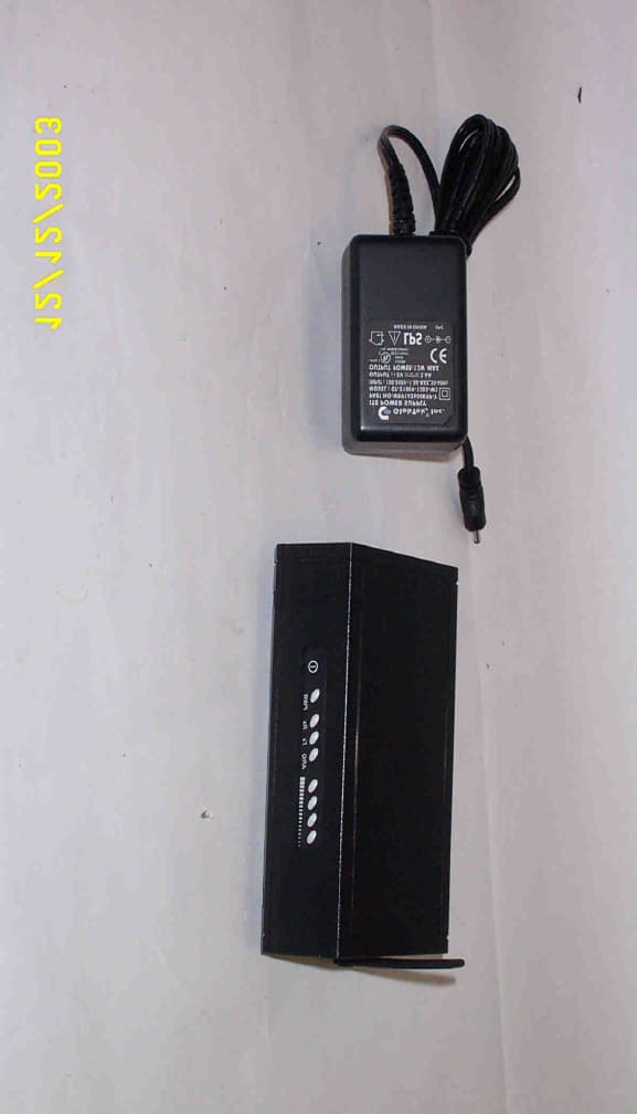
Click to zoom
Application Details
- Equipment Class
- PCB - PCS Licensed Transmitter
- Date of Grant
- Mar 17, 2004
- Application Purpose
- Original Equipment
- Date of Application
- Mar 17, 2004
- Equipment Note
- Wireless Broadband Modem
- Frequency Range
- 1890.75000000 - 1894.25000000
- Company
- Flarion Technologies, Inc.
- Country
- United States
Documents & Files
Document Text
Text extracted from the exhibit documents filed with the FCC. Open a document above to read the original.
Users Manual
PAD-1000 Wireless Broadband Modem Dimenstions: 5.32" long x 3.37" wide x 1.63" high Copyright © 2004 Flarion Technologies, Inc. All rights reserved. Safety and Hazards Remember to follow any special regulations in force in any area and always power down the Wireless Broadband Modem whenever radio transmitting devices are forbidden to use it, or when it may cause interference or danger. When connecting the Wireless Broadband Modem to another device, read its user’s guide for detailed safety instructions. Do not operate the Wireless Broadband Modem in near medical equipment, life support equipment, or any other equipment which may be susceptible to any form of radio interference. In such areas the Wireless Broadband Modem should be powered off so that the device does not transmit any radio signals that could interfere with this equipment. Power down the Wireless Broadband Modem when present in an area of explosive atmosphere and obey all signs and instructions. Sparks from electronic devices may cause an explosion or fire resulting in bodily injury or even death. Users are advised to power down all electronic devices while present at a refueling center. The driver or operator of any vehicle should not operate the Wireless Broadband Modem while in control of the vehicle. Operating a vehicle while utilizing the Wireless Broadband Modem may be in violation of some state regulations. To avoid a shock hazard: • Do not connect or disconnect any cables or perform installation, maintenance, or reconfiguration of this device during an electrical storm. • The power cord must be connected to a properly wired receptacle. • Any equipment to which this product will be attached must also be connected to a properly wired receptacle. Your Wireless Broadband Modem contains and can be powered from a rechargeable Li-Ion battery. Never use a charger that is damaged or modified in any way. Use only the charger that was provided with the device. Battery charging time depends on the remaining battery charge and the type of battery and charger used. The battery can be charged and discharged hundreds of times, but the battery charge capacity will gradually degrade over time. If left unused, a fully charged battery will discharge itself over time. Do not attempt to remove and replace the battery, contact an authorized service center thru the Technical Support desk. Do not leave the battery connected to a charger for more than 7 days, since overcharging may shorten its capacity and operating life. Always try to keep the device at room temperature. A device with a hot or cold battery may not work correctly, even if the battery is fully charged. CAUTION: Danger of explosion if modem/battery is used with products/computers not approved by Flarion. The MODEM must not be co-located or operated in conjunction with any other antenna or transmitter. Use of this device in any other configuration may exceed the FCC RF exposure compliance limit. . In order to comply with FCC RF exposure requirements, the EUT must be installed and operated in such a way that a minimum separation distance of 20cm is maintained between the antenna and all persons during normal operation. PAD-1000 Wireless Broadband Modem User Guide Page 1 Table of Contents Wireless Broadband Modem BASICS....................................................................3 About the Wireless Broadband Modem.......................................................................3 About the Wireless Broadband Modem software........................................................3 What is the Mobility Manager?.....................................................................................3 Package contents.......................................................................................................43 What operating systems are supported?........................................................44 What hardware requirements must my host PC have?...............................................4 1. INSTALLATION AND CONFIGURATION ........................................................5 Handling the Wireless Broadband Modem..................................................................5 Step 1: Installing software onto host PC.........................................................5 Step 2: Connecting the Wireless Broadband Modem to host PC............................7 Step 3: Connecting to the Wireless Broadband network.......................................9 2. USING THE MODEM.................................................................................11 Monitoring the connection using Mobility Manager....................................... 12 Connection Status and Connection Time.................................................... 13 Kilobytes sent or received........................................................................ 14 Signal Strength and Signal Quality............................................................................12 Power...................................................................................................16 Close, Exit and End Session......................................................................17 Disconnecting the modem..........................................................................18 Uninstalling the software............................................................................18 3. TROUBLESHOOTNG..................................................................................................15 Problems, causes and suggestions...........................................................................15 4. TECHNICAL SPECIFICATIONS..................................................................................17 5. REGULATORY INFORMATION..................................................................................18 PAD-1000 Wireless Broadband Modem User Guide Page 2 About Flarion Flarion Technologies is mobilizing the Internet with its innovative mobile communications system - …
Text truncated - open the document above for the full version.
Attestation Statements
Bedminster One 135 Route 202/206 South Bedminster, NJ 07921 USA Phone: 908-947-7000 Fax: 908-947-7090 March 10, 2004 Federal Communications Commission Authorization and Evaluation Division Equipment Authorization Branch 7435 Oakland Mills Road Columbia, MD 21046 Subject: Request for Confidentiality Reference: FCC ID: QZX99163001 To Whom It May Concern: In accordance with 0.459 of CFR 47, Flarion Technologies, Inc. requests confidentiality for the following: - Block Diagrams/Schematics PAD Schematic71-0163-002.pdf - Parts Lists/BOM’s PAD_BOM1.xls - Tune-Up Procedures/Specifications/Descriptions RF Sys Descr 0403-2.doc and any other proprietary documents contained in or accompanying the subject test report. These documents contain detailed system and equipment descriptions and related information about the product, which Flarion considers to be proprietary, confidential, and a custom design and otherwise, would not release to the general public. Since this design is a basis from which future technological products will evolve Flarion feels that this information would be of benefit to its competitors, and that the disclosure of the information in these documents would give our competitors an unfair advantage in the market. Sincerely, William S. Clark Compliance Engineer Flarion Technologies, Inc.
ID Label/Location Info
63.50 38.10 R 3.17 TYP. NOTES 1. MATERIAL BLANK LABEL AVAILABLE FROM IDENTCO INTERNATIONAL, 28164 WEST CONCRETE DRIVE INGELSIDE, IL 60041 800-533-2559 AS THEIR THERMAL TRANSFER GLOSSY WHITE POLYESTER FILM. 2. PRINTING LABEL SHALL BE PRINTED AT MANUFACTURING LOCATION BY THE MANUFACTURER AT THE TIME OF FINAL ASSEMBLY OF THE PCMCIA CARD. 3. GRAPHICS GRAPHICS FOR THE TEXT PORTION OF THE LABEL SHALL BE PRINTED PER FLARION ARTWORK PART NUMBER 48-0163-002 REV B. 4. EUI64 CODE THE EXTENDED UNIQUE IDENTIFIER (EUI64) CODE IS UNIQUE FOR EACH PCMCIA CARD AND WILL BE ASSIGNED AT THE TIME OF PCMCIA CARD MANUFACTURE. THE EUI WILL BE A 15 CHATACTER HEXIDECIMAL STRING CONFORMING TO THE FOLLOWING FORMAT. THE FIRST 9 CHARACTERS WILL BE 00735FFFF. THE REMAINING 6 CHARACTERS WILL BE SEQUENCIAL STRING STARTING AT B10001 AND GOING AS HIGH AS A11FFFF. 5. SERIAL NUMBER THE SERIAL NUMBER (SN) IS UNIQUE FOR EACH PCMCIA CARD AND WILL BE ASSIGNED AT THE TIME OF PCMCIA CARD MANUFACTURE. THE MSN WILL BE A 10 CHARACTER NUMBER CONFORMING TO THE FOLLOWING FORMAT. 6. BAR CODE THE BAR CODE FOR BOTH THE EUI64 AND SN WILL BE PRINTED AT THE FACTORY AT THE TIME OF PCMCIA MANUFACTURE. THE BAR CODE FOR EACH SHALL CONFORM TO CODE 128 SUBSET B BAR CODE SYMBOLOGY. A EC00233 9/03 T. MOXHAM CHANGES REV B - CHANGED MT-1000 TO mT-1000 - CHANGED EIU TO EUI64 AND CHANGED LOWER CASE fS TO CAPITAL - CHANGED THE FCC ID NUMBER - MADE CHANGES TO NOTES 3, 4, 5 AND 6 B EC00282 12/03 T. MOXHAM D C B A A B C D 1 2345678 8 7 654321 THE INFORMATION CONTAINED IN THIS DRAWING IS THE SOLE PROPERTY OF FLARION TECHNOLOGIES, INC. ANY REPRODUCTION IN PART OR AS A WHOLE WITHOUT THE WRITTEN PERMISSION OF FLARION TECHNOLOGIES, INC IS PROHIBITED. PROPRIETARY AND CONFIDENTIAL NEXT ASSYUSED ON APPLICATION DIMENSIONS ARE IN MILLIMETERS TOLERANCES: FRACTIONAL ANGULAR: MACH BEND TWO PLACE DECIMAL THREE PLACE DECIMAL INTERPRET GEOMETRIC TOLERANCING PER: MATERIAL FINISH DRAWN CHECKED ENG APPR. MFG APPR. Q.A. COMMENTS: DATENAME FLARION TECHNOLOGIES, INC TITLE: SIZE B DWG. NO. REV WEIGHT: SCALE: 1:1 REVISIONS REV.DESCRIPTION DATEAPPROVED ZONE UNLESS OTHERWISE SPECIFIED: B JJG10/19/03 LABEL, TOP PRODUCT IDENTIFICATION SHEET 1 OF 1 48-0163-002 DO NOT SCALE DRAWING Flarion Technologies Inc. mT-1000 Wireless Broadband Modem FCC ID: QZX99163001 Manufactured in USA EUI64: 00735FFFFB10001 "BarCode" SN:1234567890 "BarCode" LISTED I.T.E. 61EB
Test Report
NTS File: 40420-04-fcc24. FTI, Revision 1 MJO #: 40375-04 National Technical Systems Page 1 of 39 FCC Compliance Report Part 24 Certification For Flarion Technologies, Inc. mT-1000 Wireless Broadband Modem Prepared By: National Technical Systems 36 Gilbert Street South Tinton Falls, NJ 07724 Phone: 732 936 0800 Fax: 732 936 0700 E-mail: [email protected] NTS File: 40420-04-fcc24. FTI, Revision 1 MJO #: 40375-04 National Technical Systems Page 2 of 39 FCC Compliance Report Part 24 Certification For Flarion Technologies, Inc. mT-1000 Wireless Broadband Modem Date : 3/12/04 MJO # : 40420-04 File : 40420-04-fcc24.FTI Revision # : 1 Product : Wireless Broadband Modem Manufacturer : Flarion Technologies, Inc. P.O. # : NR0289 This report shall not be reproduced, except in full, without the written approval of NTS, Inc. The test results relate only to the items tested. NTS File: 40420-04-fcc24. FTI, Revision 1 MJO #: 40375-04 National Technical Systems Page 3 of 39 Product : Wireless Broadband Modem Model : mT-1000 Serial Number : 33943503470023 Manufacturer : Flarion Technologies, Inc. Address : 135 Route 202/206 South Bedminster, NJ 07921 USA Phone : 908 947 7052 Fax : 908 997 2050 Date Received : 9/8/03 Contact : Bill Clark Test Laboratory : National Technical Systems 36 Gilbert Street South Tinton Falls, NJ 07724 USA Phone: 732 936 0800 Fax: 732 936 0700 E-mail: [email protected] Prepared By : Mark S. Betts Date: 3/12/04 (Senior EMC Test Engineer) Reviewed By : Mark S. Betts Date: 3/12/04 (Program Manager) Approved By : Richard C. Gaynor Date: 3/12/04 (Facility Manager) NTS File: 40420-04-fcc24. FTI, Revision 1 MJO #: 40375-04 National Technical Systems Page 4 of 39 Table of Contents 1. General Description:..............................................................................................................................................5 2. Classification and Environment:............................................................................................................................5 3. Test Summary:.......................................................................................................................................................5 4. Test Report Summary:...........................................................................................................................................5 4.1. Test Sample Description:.......................................................................................................................5 4.1.1. Block Diagram:......................................................................................................................................5 4.1.2. EUT Equipment List:.............................................................................................................................5 4.1.3. EUT Cabling:.........................................................................................................................................6 4.2. Test Configuration:.................................................................................................................................6 4.2.1. EUT Electrical Mode of Operation:.......................................................................................................6 4.2.2. Software/Firmware:................................................................................................................................6 4.3. Test Procedure:.......................................................................................................................................6 4.4. Test Results and Data:............................................................................................................................6 4.4.1. Transmitter Conducted Power Output:...................................................................................................7 Transmitter Conducted Power Output Report........................................................................................8 4.4.2. Transmitter Occupied Bandwidth:........................................................................................................12 Transmitter Occupied Bandwidth Laboratory Report..........................................................................13 4.4.3. Frequency vs. Temperature..................................................................................................................16 Frequency vs. Temperature Laboratory Report....................................................................................17 4.4.4. Frequency vs. Voltage..........................................................................................................................20 Frequency vs. Voltage Laboratory Report...........................................................................................21 4.4.5. Transmitter Conducted Spurs:..............................................................................................................24 Transmitter Conducted Spurs Report...................................................................................................25 4.4.6. Transmitter Radiated Spurs:.................................................................................................................28 Transmitter Radiated Spurs Report......................................................................................................29 4.4.7. Transmitter Band/Block Edge:.............................................................................................................32 Transmitter Band/Block Edge Laboratory Report................................................................................33 5. Test Equipment:...................................................................................................................................................36 6. References:............................................................................................................…
Text truncated - open the document above for the full version.
Test Setup Photos
NTS File: 40420-04-fcc24.FTI, Revision 0 MJO #: 40375-04 National Technical Systems Page 38 of 39 EUT Test Setups NTS File: 40420-04-fcc24.FTI, Revision 0 MJO #: 40375-04 National Technical Systems Page 39 of 39 EUT Test Setups, Continued
Contact Information
Applicant
William S Clark(Compliance Engineer)
Technical Contact
PCTEST Engineering Lab., Inc.Randy Ortanez
[email protected]410-290-6652
6660-B Dobbin Road · Columbia, Maryland · United States
Test Firm
National Technical Systems (NTS)David Potpinka
Technical Specifications
| # | Rule Parts | Frequency Range | Power Output | Emission | Tolerance |
|---|---|---|---|---|---|
| 1 | 24E | 1.89 GHz - 1.89 GHz | 570.00 mW | 1M28W7D | 20.0000000000 Hz |
Other Applications from Flarion Technologies, Inc.
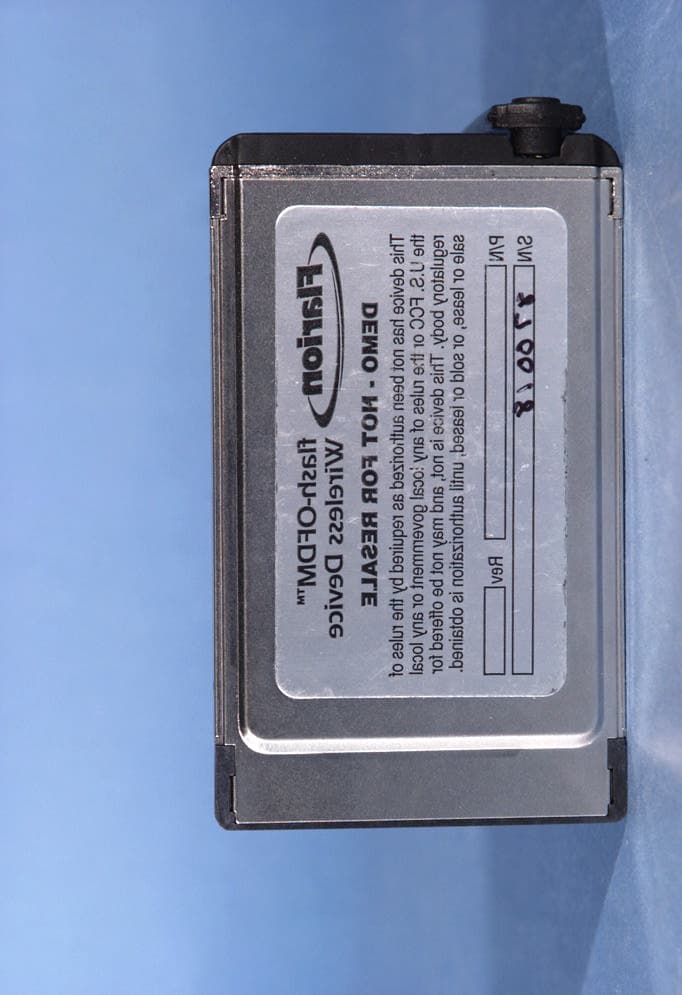
QZX99171001
Jul 07, 2005PCMCIA Wireless Network Card
Equipment Class
TNB - Licensed Non-Broadcast Station Transmitter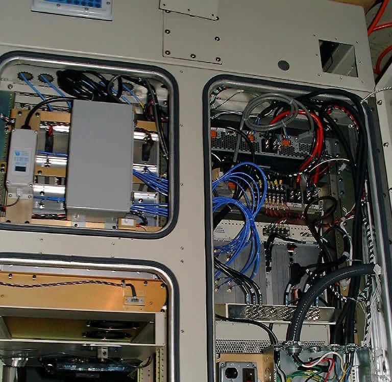
QZXBS2000700
May 12, 2005Radio Router Outdoor Base Station
Equipment Class
TNB - Licensed Non-Broadcast Station TransmitterQZXBS1000700
May 12, 2005Radio Router Indoor Base Station
Equipment Class
TNB - Licensed Non-Broadcast Station Transmitter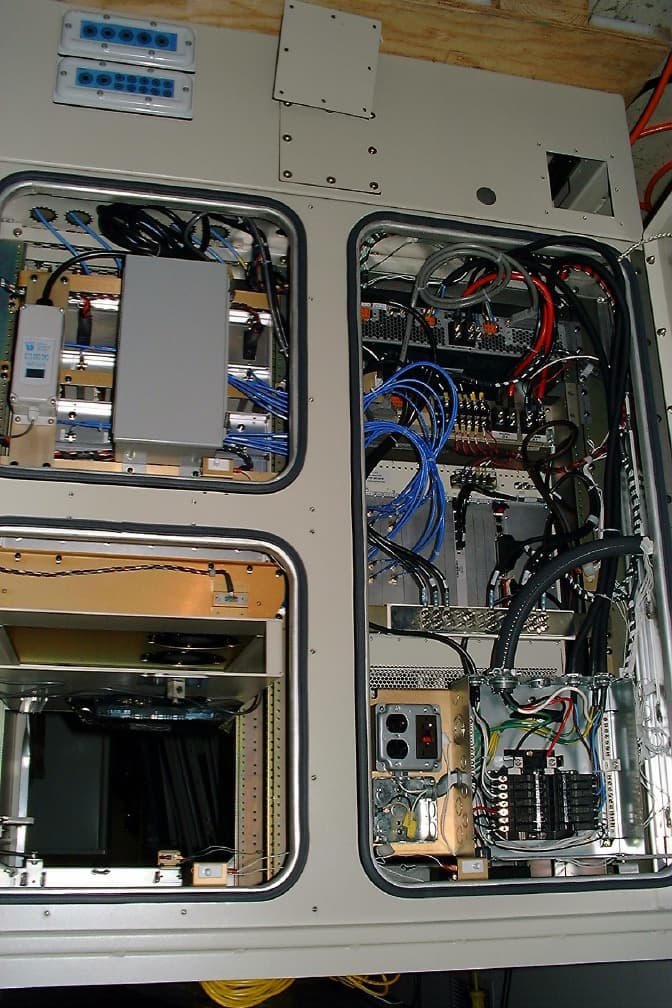
QZXBS200019
Feb 23, 2004Radio Router Outdoor Base Station
Equipment Class
PCB - PCS Licensed Transmitter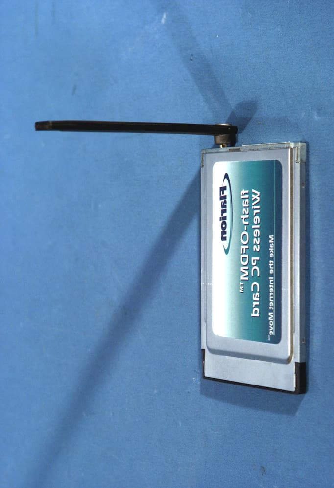
QZXPC100019
Oct 01, 2003PCMCIA Wireless Network Card
Equipment Class
PCB - PCS Licensed Transmitter