R2EELITEWireless air conditioning plant control system.
Seeley International Pty. Ltd.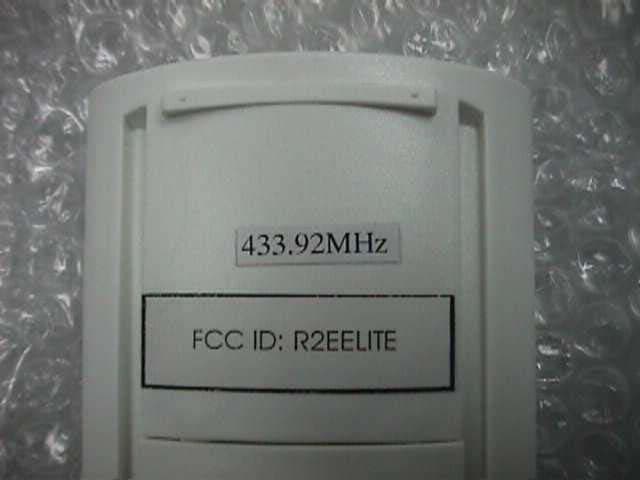
Click to zoom
Application Details
- Equipment Class
- DSC - Part 15 Security/Remote Control Transmitter
- Date of Grant
- Jun 22, 2004
- Application Purpose
- Original Equipment
- Date of Application
- Apr 08, 2004
- Equipment Note
- Wireless air conditioning plant control system.
- Frequency Range
- 433.23000000 - 434.32000000
- Country
- Australia
Documents & Files
Document Text
Text extracted from the exhibit documents filed with the FCC. Open a document above to read the original.
Users Manual
AUTOCOOL PM FAN SPEED ECONOMY BATTERY LOW REMOTE CONTROL ownerís manual Æ page introduction 2 Hello and congratulations on purchasing a Breezair Ducted Cooler for your home. Breezair coolers have been designed to provide quiet, reliable and cool comfort. At Seeley International we manufacture Breezair evaporative coolers from the highest quality materials, and we have designed the product to provide many years of economical, trouble free cooling. Please take a few moments to read these operating instructions, so that the most can be gained from this investment. Breezair coolers are fitted with either a Wall Mounted Thermostat Control or a RemoteThermostat Control. Please refer to the relevant section in this manual for instructions on how to operate either system.Also, please be aware of the components and features that are fitted to your particular cooler. Keep these instructions in a safe place for future reference. EFFECTIVE COOLING To provide efficient cooling or ventilation the building must have sufficient exhaust openings to the outside of the building.To assist air flow, open windows and doors that are farthest from the outlet vent in each room. In these rooms, provide an exhaust opening about 2 times the vent size of the room. Where the design of the building prevents adequate exhaust, consideration should be given to the provision of mechanical extractions, such as an exhaust fan. In areas where temperatures can cause water supply pipes to freeze, a drain down facility should be provided during the installation. This drain down facility must be activated prior to freezing conditions, to avoid possible damage to the cooler components. Important Note! Æ Æ Æ Æ Æ range thermost at 3 Wall MountedThermostat Control (wall control) RemoteThermostat Control (remote control) AUTOCOOL PM FAN SPEED ECONOMY REMOTE CONTROL ILL239-D ILL1140-A Æ page content s 4 RemoteThermostat Control..............5 Wall MountedThermostat Control...11 Bleed Funnel & Drain Valve............15 Power Outages...............................15 Seasonal Maintenance...................16 Troubleshooting..............................18 Service & Warranty.........................20 Æ ther mostat control remote 5 SETTING THE CLOCK TURNINGTHE COOLER Set the clock on the remote control before proceeding with any other programming. The clock can only be set with the remote control switched OFF. Hold the button down for over 2 seconds, until the hour flashes. Use the and buttons to change the hour. To change minutes, press the button again. Change the minutes using the and buttons. To lock in the time setting, and enter the OFF state, press the button.The display will stop flashing. The remote control is switched on and off using the button.The memory will store The clock can be set to either 12 or 24 hours (see page 10). If the clock is set to 12 hours make sure that the AM/PM displayed on the screen is correct.AM/PM will change with adjustment of the hour. ON and use the settings from when the cooler was last used. Once the remote control is on, you can choose between MANUAL, AUTO andAUTO TIMER modes by pressing the button. decreaseincrease MANUALMODE With the remote control ON, press the button until MANUALis shown in the top left corner of the display. The button is used to select VENT(where fresh air is being delivered without being cooled) or COOL. Once either COOLor VENT has been selected, the remote control will maintain a constant fan speed.This is indicated by the bar graph in the centre of the display. Toorthe fan speed required, press either the or buttons. MANUAL COOL FAN SPEED ILL1108-A MANUALVENT FAN SPEED ILL1109-A ILL1104-A PM Æ 6 AUTO MODE The remote control contains a thermostat. InAUTO mode the cooler is controlled automatically, based on your pre-comfort level.The cooler will adjust the fan speed, switch between COOLand VENTand turn itself off. However, the sequence and regularity at which these settings change will differ with each operation of the cooler. As the remote control senses room conditions, the heat from direct sunlight or electrical appliances. Likewise placing the remote control in cupboards or drawers or under cooling vents will affect the coolerís operation. To set theAUTO mode press the button untilAUTO is displayed. Ten levels of comfort are available with the remote control. While inAUTO mode pressing the and buttons will adjust the level of required comfort.The display selected comfort control settings will be influenced by will show your selection by indicating a level between 1 and 10. WARMER or COOLER will be displayed on the screen as settings are changed. Begin by pressing the button.The hour displayed will start flashing and the word ON will appear on the screen.Then use the and buttons to change the hour value. AUTO TIMER MODE AUTO TIMER mode can be selected by using the button. Once theAUTO TIMER mode is selected the cooler will only operate during the programmed time period. Programming the timer must be performed beforeAUTO TIMER can be activated.This can be done while in any mode, even when it is OFF. There are 7 steps involved in setting the AUTO TIMER. NOTE:After pressing the button the display will revert back to the previous setting if no buttons are pressed within 4 seconds. To program the timer use the following sequence: (1) Setting the ON time hour AUTO TIMER ON ILL1112-A ther mostat control remote AUTO FAN SPEED ILL1105-A PM Æ 7 (2) Setting the ON time minutes (3) Setting the OFFtime hour Press the button.The minutes displayed will start flashing and the word ON will appear on the screen.Then use the and buttons to change the minute setting. Press the button.The hour displayed will start flashing and OFF will be displayed.Then use the and buttons to change the hour. Press the button.The minutes displayed will start flashing and the word OFF will appear. Then use the and buttons to change the minute setting. (4) Setting the OFFtime minutes AUTO TIMER ON ILL1113-A A…
Text truncated - open the document above for the full version.
Cover Letter(s)
Doc ID: 811 FCC confidentiality.doc Sensolid Pty Limited A.C.N. 001 088 017 T/A Austest Laboratories Reg. Office, Ground Floor 35 Alleyne Street Chatswood NSW 2067 Australia 18 th June 2004 Re: FCC Application for Seeley International Pty. Ltd. Re: FCC ID R2EELITE Applicant: Seeley International Pty. Ltd. Correspondence Reference Number: 26970 731 Confirmation Number: EA385403 Attention: Mr. Steven Dayhoff Dear Mr. Dayhoff, Please arrange confidentiality status for all exhibits filed under this application, as referenced in your email dated 11 th June 2004. Thanks for your assistance with this matter. Best Regards, Paul Kay EMC Manager Austest Laboratories Adelaide, South Australia
External Photos
Specification for RF Thermostat Document number: ES-C010 Date: 23.8.02 Reproduction of this document in part or in full to third parties is not permitted without written authority from Seeley International Pty. Ltd. 1.0 INTRODUCTION This is the Radio Frequency Link specification for the electronic thermostat module (Handset) that forms part of the Breezair Freedom TM Control System. The Handset is a battery powered thermostat with a Liquid Crystal Display (LCD). The Handset utilises Radio Frequency technology to communicate with the Evaporative Cooler control system. By sensing the room temperature and controlling the operations of the fan and pump, the Handset can be used to control the comfort level of the temperature in a building. In addition, the Handset also provides features like programmable time operations, pump and drain valve control, Water manager operation, time of day clock, economy mode, automatic and manual control modes. 2.0 APPLICABLE STANDARDS FCC requirements for product sale in USA into fixed residential, commercial and industrial installations. FCC part 15 3.0 SPECIFICATIONS 3.1 BATTERY REQUIREMENTS Operating Voltage : 4.5v d.c. Batteries : 3 x 1.5v d.c. (AAA alkaline) Battery life : minimum 1000 hours of operation Memory Backup : 3 minutes after batteries removed 3.2 OPERATING TEMPERATURE Operating temperature : 0 C to 40 C Storage temperature : 0 C to 50 C Relative humidity : 0 to 85% non condensing 3.3 TRANSMISSION FREQUENCY AND RANGE Carrier frequency : 433.92 ±0.5 MHz Data rate : 300 Baud RF Output Power : 4.0 ±0.5μW Modulation : ASK Range : 50 metres 3.3 PERIODIC TRANSMISSION When operating : sends the data packet once every 10 minutes When off : none 3.3 DATA PACKET Packet size : 3 x 6 byte packets (8 bits per byte), total 18 bytes Transmission time : 620 mSec 3.3 DATA CONFIGURATION Byte 1 : Preamble 0ffH fixed Byte 2 : Header 0aaH fixed Bytes 3 - 5 : Data 00H to 07fH variable Byte 6 : CRC (last byte) 00H to 0ffH variable 4.0 RECEIVER QwikRadio Conventional Super Heterodyne Receiver (MICRF011BM) from MICREL 5.0 BLOCK DIAGRAM 6.0 FCC ID LABEL FCC label for RF transmitter: 12mm x 40mm (white background), 10pt font DIP SWITCHES μPROCESSOR LCD DISPLAY THERMAL SENSING KEYPAD RF TRANSMITTER BATTERY SUPPLY FCC ID: R2EELITE 7.0 PICTURES
ID Label/Location Info
Specification for RF Thermostat Document number: ES-C010 Date: 23.8.02 Reproduction of this document in part or in full to third parties is not permitted without written authority from Seeley International Pty. Ltd. 1.0 INTRODUCTION This is the Radio Frequency Link specification for the electronic thermostat module (Handset) that forms part of the Breezair Freedom TM Control System. The Handset is a battery powered thermostat with a Liquid Crystal Display (LCD). The Handset utilises Radio Frequency technology to communicate with the Evaporative Cooler control system. By sensing the room temperature and controlling the operations of the fan and pump, the Handset can be used to control the comfort level of the temperature in a building. In addition, the Handset also provides features like programmable time operations, pump and drain valve control, Water manager operation, time of day clock, economy mode, automatic and manual control modes. 2.0 APPLICABLE STANDARDS FCC requirements for product sale in USA into fixed residential, commercial and industrial installations. FCC part 15 3.0 SPECIFICATIONS 3.1 BATTERY REQUIREMENTS Operating Voltage : 4.5v d.c. Batteries : 3 x 1.5v d.c. (AAA alkaline) Battery life : minimum 1000 hours of operation Memory Backup : 3 minutes after batteries removed 3.2 OPERATING TEMPERATURE Operating temperature : 0 C to 40 C Storage temperature : 0 C to 50 C Relative humidity : 0 to 85% non condensing 3.3 TRANSMISSION FREQUENCY AND RANGE Carrier frequency : 433.92 ±0.5 MHz Data rate : 300 Baud RF Output Power : 4.0 ±0.5μW Modulation : ASK Range : 50 metres 3.3 PERIODIC TRANSMISSION When operating : sends the data packet once every 10 minutes When off : none 3.3 DATA PACKET Packet size : 3 x 6 byte packets (8 bits per byte), total 18 bytes Transmission time : 620 mSec 3.3 DATA CONFIGURATION Byte 1 : Preamble 0ffH fixed Byte 2 : Header 0aaH fixed Bytes 3 - 5 : Data 00H to 07fH variable Byte 6 : CRC (last byte) 00H to 0ffH variable 4.0 RECEIVER QwikRadio Conventional Super Heterodyne Receiver (MICRF011BM) from MICREL 5.0 BLOCK DIAGRAM 6.0 FCC ID LABEL FCC label for RF transmitter: 12mm x 40mm (white background), 10pt font DIP SWITCHES μPROCESSOR LCD DISPLAY THERMAL SENSING KEYPAD RF TRANSMITTER BATTERY SUPPLY FCC ID: R2EELITE 7.0 PICTURES
Internal Photos
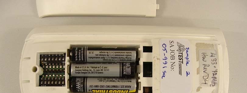
04-811sa Internal photos
Test Report
____________________________________________________________________________________ Report number: 04-811-1sa Date: 8 th April 2004 Page 1 of 18 Sensolid Pty. Limited A.C.N. 001 088 017, T/A Austest Laboratories Reg. Office, 33 Alleyne Street Chatswood NSW 2067 Ground Floor, 35 Alleyne St, Chatswood NSW 2067 Australia. Tel (61-2) 9882 6500 Fax (61-2) 9882 6600 TEST REPORT COMPLIANCE TESTING REPORT FOR REMOTE CONTROL THERMOSTAT TRANSMITTER MODEL NO: SEELEY FREEDOM CLIENT: SEELEY INTERNATIONAL PTY. LTD. ADDRESS: 1-11 ROTHESAY AVENUE, ST. MARYS, SOUTH AUSTRALIA 5042 REPORT NUMBER: 04-811-1SA FILE NUMBER: 04-811SA DATE OF ISSUE: 8 TH APRIL, 2004 TEST STANDARD: FCC PART 15.231 RESULT: COMPLIES TESTED AND COMPILED BY: PAUL KAY APPROVED BY: P. KAY EMC MANAGER CHECKED BY: E. NOWAK Results appearing herein relate only to the sample(s) tested. This report may not be reproduced in any form unless done so in full. Original copies of reports are printed on Austest Laboratories official Test Report letterhead, printed in reflex blue. This report is issued errors and omissions exempt and is subject to withdrawal at Austest Laboratories discretion. This document is copyright by Austest Laboratories with a limited grant of reproduction issued to Austest Laboratories customers subject to the above conditions. ____________________________________________________________________________________ Report number: 04-811-1sa Date: 8 th April 2004 Page 2 of 18 Sensolid Pty. Limited A.C.N. 001 088 017, T/A Austest Laboratories Reg. Office, 33 Alleyne Street Chatswood NSW 2067 Ground Floor, 35 Alleyne St, Chatswood NSW 2067 Australia. Tel (61-2) 9882 6500 Fax (61-2) 9882 6600 TEST REPORT CONTENTS: 1. Client Information..........................................................................................................................3 2. Equipment Under Test (EUT)......................................................................................................3 2.1 Identification of the EUT..........................................................................................................3 2.2 Additional Information about the EUT.....................................................................................3 2.3 Peripheral equipment................................................................................................................3 3. Test Specifications..........................................................................................................................4 3.1 Standard selection and justification..........................................................................................4 3.2 Test Facility...............................................................................................................................4 3.3 Additions to, deviations and exclusions from standards and accreditation..............................4 3.4 Test equipment..........................................................................................................................5 3.5 References.................................................................................................................................6 4. Labelling Requirements................................................................................................................6 4.1 Equipment and documentation labels.......................................................................................6 4.2 Information to the user..............................................................................................................6 5. Test summary.................................................................................................................................7 6. Modifications..................................................................................................................................7 7. Test results......................................................................................................................................8 7.1 15.231(a) Transmitter auto-off..................................................................................................8 7.1.1 Test Conditions.................................................................................................................8 7.1.2 Operation Modes...............................................................................................................8 7.1.3 Transmitter on-time Test Data..........................................................................................8 7.1.4 Summary...........................................................................................................................9 7.2 15.231 (b) Radiated Spurious Emissions................................................................................10 7.2.1 Test Conditions...............................................................................................................10 7.2.2 Operation Modes.............................................................................................................10 7.2.3 Emissions Data................................................................................................................10 7.2.4 Summary.........................................................................................................................11 7.3 15.231 (c) Occupied Bandwidth.............................................................................................12 7.3.1 Test Conditions...............................................................................................................12 7.3.2 Operation Modes.............................................................................................................12 7.3.3 Bandwidth Data...............................................................................................................12 7.3.4 Summary.........................................................................…
Text truncated - open the document above for the full version.
Contact Information
Applicant
Craig Simkin
Technical Contact
Austest LaboratoriesPaul A Kay
+61 8 8288 7400
PO Box · Adelaide · Australia
Test Firm
Austest LaboratoriesPaul Kay
Technical Specifications
| # | Rule Parts | Frequency Range | Power Output |
|---|---|---|---|
| 1 | 15.231(e) | 433.23 MHz - 434.32 MHz | - |
Other Applications from Seeley International Pty. Ltd.
R2ESIA06
Jul 06, 2006Remote control transmitter
Equipment Class
DSR - Part 15 Remote Control/Security Device Transceiver