R2H13281-1VHF Data Link Device
Software Development Alternatives, Inc.
Click to zoom
Application Details
- Equipment Class
- TNB - Licensed Non-Broadcast Station Transmitter
- Date of Grant
- May 27, 2004
- Application Purpose
- Original Equipment
- Date of Application
- May 27, 2004
- Equipment Note
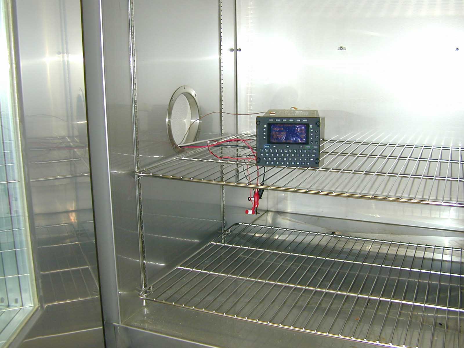
- VHF Data Link Device
- Frequency Range
- 118.00000000 - 136.97500000
- Country
- United States
Documents & Files
Document Text
Text extracted from the exhibit documents filed with the FCC. Open a document above to read the original.
Users Manual
Document Number: 5630-5101-A00 Rev. B 11/13/03 DLINK+ Users Manual SLC Doc Number 13278 Spectra Lux Corporation 12335 134 th Court NE Redmond, WA 98052 USA Tel: (425) 823-1801 Fax: (425) 823-4517 Email: [email protected] RESTRICTION ON USE, PUBLICATION, OR DISCLOSURE OF PROPRIETARY INFORMATION This document contains information proprietary to Spectra Lux Corporation, or to a third party to which Spectra Lux Corporation may have a legal obligation to protect such information from unauthorized disclosure, use, or duplication. Any disclosure, use, or duplication of this document or of any of the information contained herein for other than the specific purpose for which it was disclosed is expressly prohibited, except as Spectra Lux Corporation may otherwise agree in writing. Preparer: Date: Engineer: Date: Product Manager: Date: Quality Manager: Date: CHANGE RECORD Paragraph Description Of Change Approval/ Date Revision Initial release - 1 Introduction This document establishes one part of the baseline of configuration data for the Spectra Lux Corporation product called Dlink+. This product was originally co-developed under the Pentar name “CMS-1000”. In October of 2003, Pentar Systems Inc. and Spectra Lux Corporation dissolved their team, and agreed that each company should proceed to develop the future of the product individually. TSO approval was granted for the product prior to the decision to separate the programs. Spectra Lux Corporation is therefore establishing a certification package based on the previous documentation. Appendix A of this document contains Pentar document 5630-5101-A00, Rev A. This certification baseline document allows us to establish an SLC numbering system for documentation of future differences between the Dlink+ product and the CMS-1000 product. Please refer to Spectra Lux Corporation document 13258, “Configuration Description Document” for a table that describes correspondence of all Spectra Lux Corporation documents to Pentar Documents. 2 Appendix A See the attached document for Pentar 5630-5101-A00, Rev A. CMS-1000 Communication Management System Users Manual 19820 North Creek Parkway, Suite 102 Bothell, WA 98011 USA Tel: (425) 424-3370 Fax: (425) 424-3380 Email: [email protected] RESTRICTION ON USE, PUBLICATION, OR DISCLOSURE OF PROPRIETARY INFORMATION This document contains information proprietary to PENTAR Avionics, or to a third party to which PENTAR Avionics may have a legal obligation to protect such information from unauthorized disclosure, use, or duplication. Any disclosure, use, or duplication of this document or of any of the information contained herein for other than the specific purpose for which it was disclosed is expressly prohibited, except as PENTAR Avionics may otherwise agree in writing. Preparer: Date: Engineer: Date: Product Manager: Date: Quality Manager: Date: CMS-1000 Users Manual 5630-5101-A00 Rev. B i CHANGE RECORD Paragraph Description Of Change Approval/ Date Revision All Initial release L. Thorpe 1/18/02 - Footers Changed rev to A and date to 12/20/02 A. Pickrell 12/10/02 A All Corrected various minor spelling and grammar errors 2.1 Added sentence about options GPS connector 2.1 and subsections Changed Appendix A references to be a pin assignment table instead of a reference to page 2 of a system assembly drawing Appendix A Changed Appendix A to contain pin assignment tables instead of a system assembly drawing. Footers Changed rev to B, date to 11/13/03, and corrected footer document numbers after title page and Change record A. Pickrell 11/13/03 B 2.1 Added note that software is certified to DO178B level D. Users Manual 5630-5101-A00 Rev. B ii CONTENTS 1 SCOPE................................................................................................................................................... 1 1.1 System Overview............................................................................................................................ 1 1.2 Overview of Manual Contents ........................................................................................................ 1 2 INSTALLATION..................................................................................................................................... 2 2.1 General ........................................................................................................................................... 2 2.1.1 11 Pin Connector..................................................................................................................... 2 2.1.2 61 Pin Connector..................................................................................................................... 3 3 CONFIGURING THE CMS-1000 ........................................................................................................... 6 3.1 Downloading a configuration .......................................................................................................... 6 3.2 Editing a configuration .................................................................................................................... 6 3.3 Downloading a database ................................................................................................................ 6 3.3.1 Database Compiler.................................................................................................................. 7 3.4 The database.................................................................................................................................. 8 3.4.1 Menu Definitions...................................................................................................................... 8 Line select commands (L1 – L6, R1 – R6) .......................................................................................... 14 3.4.2 User Functions ...................................................................................................................... 15 3.4.…
Text truncated - open the document above for the full version.
Attestation Statements
TCB7 05/28/04 Page 1 of 4 General Agreement I, the undersigned, a representative of Spectra Lux Corporation, having its registered offices at 12335 134 th Court NE, Redmond, Washington 98052, hereinafter referred to as the "Applicant", acting for and on behalf of the applicant accept the following terms as provided in this General Agreement. Applicant authorizes CKC Certification Services, having its registered offices at 4933 Sierra Pines Dr., Mariposa, CA 95338, hereinafter referred to as "CKC CS", to perform the required certification in compliance with the articles of this agreement and the current Federal Communications Commission (FCC) regulations. Article 1: Regulation for certification and inspection The Applicant agrees that the stipulations of Chapter 47 of the Code of Federal Regulations (CFR47) apply to this agreement. Article 2: Rights and obligations 2.1 Compliance. The Applicant agrees that the equipment, process or service certified shall comply with all the Federal Communications Commissions (FCC) technical and administrative requirements specified in Chapter 47 of the Code of Federal Regulations (CFR47). 2.2 Certificate. Applicant shall endeavor to ensure that no certificate or report or any part thereof is used in a misleading manner. Equipment shall be represented as certified only if it complies with the FCC regulations and is labeled as required by the FCC. The Applicant shall use certification only to indicate that products are certified in conformity with the specified FCC regulations. 2.3 Quality. The Applicant agrees that the certified products shall be produced to the same specifications. The Applicant further agrees to correct any deficiencies found in products or services that affect compliance with the relevant certification. 2.4 Audits. CKC CS may perform audits of Applicants equipment and documentation. Applicant shall make all necessary arrangements for the conduct of the audit and/or evaluation, including provision for examining documentation and access to records (including internal audit reports) and personnel for the purpose of evaluation (e. g. testing, inspection, assessment, surveillance, reassessment) and resolution of complaints. 2.5 Samples. Although CKC CS attempts to keep the need for samples to a minimum, the Applicant shall furnish, without charge, such samples of Equipment for examination and testing purposes as may be required from time to time by CK CS. Such samples will be returned at Applicants expense if requested by Applicant. CK CS shall not be responsible for the condition of such samples as such samples may be damaged or destroyed during testing. The Applicant shall make all necessary arrangements for the conduct of the evaluation and subsequent surveillance activities as necessary. In accordance with CFR 47, the Applicant agrees to provide products for CKC CS Deleted: the Page 2 of 4 surveillance activities within 14 days of such request. Fees involved for evaluation and/or surveillance samples shall follow Article 3 of this agreement. 2.6 Publicity. CKC CS will permit the use of appropriate references to CKC CS, in advertising or promotional material solely in connection with the specific products that it has certified, provided that the reference to CKC CS in no way tends to create a misleading impression as to the nature of CKC CS's findings, coverage or service. Applicant will not use its product certification in such a manner as to bring CKC CS, the certification body, into disrepute and will not make any statement regarding its product certification that CKC CS may consider misleading or unauthorized. 2.7 Testing and Certification. The rights of CKC CS under this Agreement do not relieve Applicant of any part of its obligations under this Agreement. Applicant recognizes that the opinions and findings of CKC CS represent its judgment given with due consideration to the type of certification, the necessary practical limitations and in accordance with its objects and purposes. Applicant recognizes that many tests specified in the FCC requirements may be inherently hazardous and agrees that CKC CS neither assumes nor accepts any responsibility for any injury or damage to Applicants property or personnel that may occur during or as a result of tests, whether performed in whole or in part by Applicant or CKC CS, and whether or not any device, test equipment, facility or personnel for or in connection with the test is furnished by Applicant or CKC CS. 2.8 Confidentiality. CKC CS is responsible for seeing that confidentiality is maintained by its employees concerning all confidential information with which they become acquainted as a result of their contacts with the Applicant. Except as required by regulation or law, information gained by CKC CS in the course of certification activities about a particular product, shall not be disclosed to a third-party without the written consent of the Applicant. Where the law or regulation requires information to be disclosed to a third-party, the Applicant shall be informed of the information provided as permitted by the applicable regulation or law . (NOTE) The Applicant is hereby notified that for certification within the US, CKC CS, in accordance with 47CFR 2.962 and/or 47CFR 68.162 (as applicable), is obligated to upload all information and files to the FCC database. All information on the FCC database is public information. Exceptions to this are material that is classified as confidential. 47 CFR subpart 0.459 has designated what can be determined as confidential material. If the Applicant desires to have certain information held as confidential, it is the responsibility of the Applicant to so designate this confidential material. The FCC however, retains the right to accept or deny the request for confidentiality. 2.9 Complaints. Applicant shall keep a record of all complaints made known to the supplier relating to a product’s compliance with the requirements of the relevant standard and…
Text truncated - open the document above for the full version.
Attestation Statements
DC Voltages Applied and DC currents of final RF Device in Normal Operation: Bias Driver PA Voltage: 3.97V Bias HPA Voltage: 3.72V Driver PA Current: 234 mA HPA Current: 1.61 A Total Current: 1.844 A Total Gain: 31 dBm
Cover Letter(s)
Attachment A to Letter of Confidentiality from Michael Burke to FCC dated March 19, 2004 Reference: (1) Letter from Les Thorpe to CKC dated April 14, 2004. Subject of Letter is “Submission of Data Delineated in FCC Submittal Checklist”. Letter reference number is 04-14-04-LFT0001. The following attachments of Reference (1) are considered proprietary information and are therefore considered confidential. Attachments: (6) Appendix F: DLink+ Systems Requirements Document (8) Appendix H: Schematics
Cover Letter(s)
From: Les Thorpe [[email protected]] Sent: Friday, May 28, 2004 9:47 AM To: Randy Clark (E-mail) Subject: Declaration of Design Changes Hi Randy, I've attached a pdf version of the letter which delineates the design changes that have occurred since certification testing for your review. Thanks for you help. <<Design Changes Declaration.pdf>> Les Thorpe Product Line Manager Spectra Lux Corporation 12335 134th Court NE Redmond, WA 98052 Tel: 425-823-1801 Ext. 620 Fax: 425-823-4517 Cell: 206-661-0798 e-mail: [email protected]
Cover Letter(s)
SpectraLux Corporation 12335 134th Court NE Redmond, WA 98052 5/28/2004 Letter Reference Number: 05-28-04-LFT001 Randal Clark Evaluation Engineer CKC Laboratories, Inc. 5473-A Clouds Rest Mariposa, CA 95338 Tel: 800-500-4362 ext. 226 Fax: 209-742-6133 Dear Randy, Subject: Declaration of Design Changes After Completion of Certification Testing The purpose of this correspondence is to provide a declaration of the design changes to the DLink+ that have occurred since any and all certification/qualification testing. To date, there have been no hardware design changes. The printed circuit boards used in the existing units are identical to those used in the units used for certification/qualification testing. In fact, the exact same GERBER files (the files that define the board design and layout) have been used for all units to date. There have been no component changes since any and all certification/qualification testing. The changes that have been made can be categorized into two categories; cosmetic and software. The cosmetic changes consist of changing the unit’s model name from CMS-1000 to DLink+ and the corresponding change to the units nameplate marking. The software changes have all been associated with protocol issues to allow the unit to use the ARINC VHF network. These changes have no effect on the RF modulation or output. ARINC requires complex protocol for the receiving and processing of the messages that are exchanged over their network between the aircraft and their ground stations. It should be noted that the DLink+ can only communicate via RF by using the ARINC VHF network. Please contact the undersigned if there are further questions. Sincerely, Les Thorpe Product Line Manager Spectra Lux Corporation 12335 134 th Court NE Redmond, WA 98052 Tel: 425-823-1801 x620 Fax: 425-823-4517 Cell: 206-661-0798
Cover Letter(s)
From: Les Thorpe [[email protected]] Sent: Friday, May 28, 2004 9:33 AM To: Randy Clark (E-mail) Subject: DLink+ Output Power Hi Randy, The purpose of this e-mail is to clarify the specifcation for RF output power of the DLink+ There are two requirements for RF output power, depending on the modulation mode. In mode 0 (MSK), the radiated, RF output power is 10 + 1 watts. In mode 2 (D8PSK), the radiated RF output power is 17+ 1 watts. The maximum output power that is allowed by the RTCA agency for either mode is 25 watts. This agency controls the output power spectrum requirements for this type of avionics. I hope this helps. Les Thorpe Product Line Manager Spectra Lux Corporation 12335 134th Court NE Redmond, WA 98052 Tel: 425-823-1801 Ext. 620 Fax: 425-823-4517 Cell: 206-661-0798 e-mail: [email protected]
Cover Letter(s)
5/20/2004 Letter Reference Number: 05-20-04-LFT001 Reference (1) FCC DLink+ Submittal Letter Dated April 14, 2004, Ltr. Ref. No. 04-14-04-LFT001 (2) Email from Mary Ellen to Les Thorpe dated 5/17/2004 re: additional data needed for FCC submittal Mary Ellen Clayton Report Department CKC Laboratories, Inc. 5473-A Clouds Rest Mariposa, CA 95338 Tel: 800-500-4362 ext. 226 Fax: 209-742-6133 Attachments: (1) Appendix E: Letter Requesting Confidentiality (2) Appendix M: Test Results Dear Mary Ellen, Subject: Addendum to Submission of Data Delineated in FCC Submittal Checklist The purpose of this correspondence is to provide and update to Reference (1) based upon items listed in Reference (2). Additionally, the purpose is to resubmit a modified Appendix E of Reference (1). The following are the items listed in Reference (2) with responses: Item 1: I will take care of this one. Mary Ellen Response: No action required. Item 2: Please provide RF power output data showing compliance to FCC CFR 47 Section 87.131/ 87.137 and FCC CFR 47 Section §2.1046. Please note the following - 2.1046 (a) For transmitters other than single sideband, independent sideband and controlled carrier radiotelephone, power output shall be measured at the RF output terminals when the transmitter is adjusted in accordance with the tune-up procedure to give the values of current and voltage on the circuit elements specified in §2.1033(c)(8). The electrical characteristics of the radio frequency load attached to the output terminals when this test is made shall be stated. 2.1046 (c) For measurements conducted pursuant to paragraphs (a) and (b) of this section, all calculations and methods used by the applicant for determining carrier power or peak envelope power, as appropriate, on the basis of measured power in the radio frequency load attached to the transmitter output terminals shall be shown. Under the test conditions specified, no components of the emission spectrum shall exceed the limits specified in the applicable rule parts as necessary for meeting occupied bandwidth or emission limitations. SpectraLux Corporation 12335 134th Court NE Redmond, WA 98052 z Page 2 May 28, 2004 Response: The power output is delineated in Reference (1). The test data has now been provided in Attachment (2). Item 3: Please provide frequency stability data showing compliance to FCC CFR 47 Section 87.133 and Section §2.1055. Response: The frequency stability is delineated in Reference (1). The test data has now been provided in Attachment (2). Item 4: Incomplete emissions designator on form 731. Please provide the entire emissions designator in accordance with CFR 47 Section 2.201 & 2.202. Response: The entire designator is 12.5WD7 (refer to Occupied Bandwidth for the test that determines the 12.5 KHz bandwidth in Appendix M). The 12 KHz was chosen as it was the maximum occupied bandwidth over the entire operating frequency range of the unit. Item 5: Please provide the occupied bandwidth data plots showing compliance to CFR 47 Section §2.1049 and 87.135/ 87.137?. Response: The occupied bandwidth was measured at the low end, mid range and upper end of the unit’s operating frequency range. The measurements were taken as close to –20 dBc as possible. The results are contained in Attachment (2). Item 6: I will take care of this one. Mary Ellen No action required. Item 7: Please provide the following information in accordance with CFR 47 Section 2.1033(6): Range of operating power values or specific operating power levels, and description of any means provided for variation of operating power. Response: In Mode 0 the minimum operating power is 9 watts. In Mode 2, the minimum operating power is 14 watts. For both modes, the maximum operating power is 25 watts. These figures are per the RTCA Minimum Operating Performance Requirements. Refer to Attachment (2) for test results. Item 8: Please provide the following information in accordance with CFR 47 Section 2.1033(7): Maximum power rating as defined in the applicable part(s) of the rules. Response: The maximum power rating is 25 watts (delineated by RTCA DO-281). Item 9: Please provide the following information in accordance with CFR 47 Section 2.1033(10): A schematic diagram and a description of all circuitry and devices provided for determining and stabilizing frequency, for suppression of spurious radiation, for limiting modulation, and for limiting power. Response: Refer to Reference (1). Item 10: Please provide the following information in accordance with CFR 47 Section 2.1033(13): For equipment employing digital modulation techniques, a detailed description of the modulation system to be used, including the response characteristics (frequency, phase and amplitude) of any filters provided, and a description of the modulating wavetrain, shall be submitted for the maximum rated conditions under which the equipment will be operated. Response: Refer to Reference (1). z Page 3 May 28, 2004 Item 11: In summary of tests required, please provide the following information in accordance with CFR 47 Section 2.1033(14): The data required by §§2.1046 through 2.1057, inclusive, measured in accordance with the procedures set out in §2.1041. Please also include set up Photos of the tests performed. Response: Refer to Attachment (2). Item 12: Please provide the appropriate antenna installation instructions in the users manual including antenna separation for RF exposure compliance? Response: This is not applicable for our unit. Item 13: Please provide a list of ALL equipment used for FCC testing and it calibration dates. Response: Refer to Attachment (2). Item 14: Please provide emissions data showing compliance to CFR 47 Section 2.1051 and 87.139. Response: Refer to Attachment (2). Item 15: Please provide emissions data showing compliance to CFR 47 Section 2.1053 and 87.139. Response: Refer to Attachment (2). Item 16: Please provide modulation characteristics data showing compliance to CFR 47 Section 2.0147 and …
Text truncated - open the document above for the full version.
Cover Letter(s)
April 14, 2004 Letter Reference Number: 04-14-04-LFT001 Reference (1): CKC FCC Part 2.1033(c) Certification Submittal Checklist Mary Ellen Clayton Report Department CKC Laboratories, Inc. 5473-A Clouds Rest Mariposa, CA 95338 Tel: 800-500-4362 ext. 226 Fax: 209-742-6133 Attachments: (1) Appendix A: Letter of Authorization (2) Appendix B: General Agreement (3) Appendix C: FCC Drug Compliance Letter (4) Appendix D: Letter of Grantee Code Authorization (5) Appendix E: Letter Requesting Confidentiality (6) Appendix F: DLink+ Systems Requirements Document (7) Appendix G: DLink+ Users Manual (8) Appendix H: Schematics (9) Appendix I: Nameplate Drawing (10) Appendix J: Photographs (11) Appendix K: ARINC AQP Phase 3 Test Report (12) Appendix L: FAA TSO Approval Letter Dear Mary Ellen, Subject: Submission of Data Delineated in FCC Submittal Checklist The purpose of this correspondence is to provide responses to the items listed in Reference (1). Enclosed with this letter is a CDROM which contains all of the Appendices. The following are the responses to the items listed in Reference (1): Equipment Name: DLink+ Model Number: The DLink+ is identical to the Model CMS-1000 except for the nameplate. In several of the appendices herein, the documentation is for the CMS-1000. All CMS-1000 documentation is directly applicable to the DLink+. The name of the CMS-1000 was changed to DLink+ for marketing reasons. Letter of Authorization: Refer to Appendix A General Agreement: Refer to Appendix B FCC Drug Compliance Letter: Refer to Appendix C Letter for Grantee Code Authorization: The grantee code authorization number is R2H. Refer to Appendix D FRN Number: 0010603223 SpectraLux Corporation 12335 134th Court NE Redmond, WA 98052 z Page 2 May 28, 2004 Letter Requesting Confidentiality: Refer to Appendix E Fees: Please invoice Spectra Lux Corporation for all fees, attention Bob Bernstein. Frequency Tolerance: Frequency Tolerance is + 5 ppm of selected frequency Operational Description: The DLink+ is a VHF Data Link device. It operates over the ARINC ground based VHF network in the frequency range of 117.975 MHz to 136.975MHz. It transmits in two modes of operation. One mode utilizes a Minimum Shift Keying (MSK) approach to modulation of the carrier frequency. The keying is between 1200 Hz and 2400 Hz. This allows for a data rate of 2400 Bits/Second. The other mode uses a Differential 8 Phase Shift Keying approach to modulation of the carrier frequency. The BIT rate for this mode is 31,500 Bits/Second (10,500 Symbols/Second, each symbol representing 3 Bits). For a more complete description, please refer to Appendix F. Name of Applicant/Manufacturer: The applicant, and the manufacturer are: Spectra Lux Corporation 12335 134 th Court NE Redmond, WA 98052 Tel: 425-823-1801 Fax: 425-832-4517 Contact: Les Thorpe Product Line Manager FCC IndentifierL R2H13281-1 Installation and Operating Instructions: Refer to Appendix G. Type or types of emissions: Emissions Designator: W7D RF Emissions From the Unit :: The unit complies with Section 21, Category M RTCA DO-160D standards for LRU RF Emissions. The following characterizes the emissions from the RF Transmitter. Spurious Emissions from Transmitter : When the transmitter is active and operating at full power, and terminated in a resistive load equal to the nominal output impedance, the power of any spurious emission at the output of the transmitter is as follows: • <0.25 microwatts within a bandwidth of 1 KHz on any frequency in the range of 9 kHz to 150 kHz • <0.25 microwatts within a bandwidth of 10 KHz on any frequency in the range of 150 kHz to 30 MHz • <0.25 microwatts within a bandwidth of 100 KHz on any frequency in the range of 30 MHz to 108 MHz • <0.25 microwatts within a bandwidth of 100 KHz on any frequency in the range of 108 MHz to 117.5 MHz • <0.25 microwatts within a bandwidth of 10 KHz on any frequency in the range of 117.5 MHz to 117.8 MHz • <0.25 microwatts within a bandwidth of 10 KHz on any frequency in the range of 137.175 MHz to 137.475 MHz • <0.25 microwatts within a bandwidth of 100 KHz on any frequency in the range of 137.475 MHz to 1 GHz Additionally, the level of spurious emissions at discrete frequencies, excluding harmonics) in the following bands does not exceed 4 nanowatts • 47 to 68 MHz • 88 to 108 MHz • 162 to 244 MHz • 328 to 336 MHz z Page 3 May 28, 2004 • 470 to 862 MHz Harmonic Emissions from the Transmitter : Harmonic emission products are less than 60 dB below rated RF output power (-60 dBc). Frequency Range: The unit operates at discrete frequencies spaced 25 kHz apart starting at 118 MHz and ending at 136.975. Range of Operating Power: When on the ground (in the airport environment) the unit’s RF power is restricted to 4 watts. When not on the ground and in Mode 0 (MSK) modulation, RF power is at 10 + 1 watts. When not on the ground and in Mode 2 (D8PSK) modulation, RF power is 15+ 1 watts. Maximum Operating Power: 16 watts DC Voltages Applied and DC currents of final RF Device in Normal Operation: Bias Driver PA Voltage: 3.97V Bias HPA Voltage: 3.72V Driver PA Current: 234 mA HPA Current: 1.61 A Total Current: 1.844 A Total Gain: 31 dBm Tune-up Procedure: The procedure for operational tuning is detailed in ARINC Specification 618-4 in section 5.6. To briefly summarize the procedure, the unit, at power up, is tuned to 131.55 MHz. It awaits an uplink (usually in the form of a squitter). The squitter is broadcast from the ARINC ground station on the base frequency (131.55 MHz) about every 2 minutes in light traffic and every 10 minutes in heavy traffic. The squitter instructs the unit what frequency to tune to and broadcast on. The unit then sends a link message and two way communications are established. During this process (while at 131.55 MHz) the unit transmits in Mode 0 (MSK). The squitter may instruct the unit to tune 136.975 MHz and indicate that the station supports Mode 2 operation (D8PSK), in which case the unit will trans…
Text truncated - open the document above for the full version.
Cover Letter(s)
Response to E04-000042-1 1. The equipment class on Form 731 should be TNB. Please correct it on the form. 2. Additional files have been uploaded to answer this question. 3. . Additional files have been uploaded to answer this question. 4.The emissions designator should be 5. . Additional files have been uploaded to answer this question. 6. This information is not required. 7. . Additional files have been uploaded to answer this question. 8. . Additional files have been uploaded to answer this question. 9. . Additional files have been uploaded to answer this question. 10. . Additional files have been uploaded to answer this question. 11. . Additional files have been uploaded to answer this question. 12. This information is not needed. 13. . Additional files have been uploaded to answer this question. 14. . Additional files have been uploaded to answer this question. 15. . Additional files have been uploaded to answer this question. 16. . Additional files have been uploaded to answer this question. 17. Please see Appendix L which was uploaded in the original submittal. 18. This information is not needed. 19. An updated confidentiality letter has been uploaded.
External Photos
DLink+ Front DLink+ Back
Internal Photos
A-IO Front A-IO Back DLink+ Inside Front DLink+ Inside Back DU-PS Front DU-PS Back
Internal Photos
IO Front IO Back SBC Front SBC Back VDL Front VDL Back
Operational Description
Operational Description: The DLink+ is a VHF Data Link device. It operates over the ARINC ground based VHF network in the frequency range of 117.975 MHz to 136.975MHz. It transmits in two modes of operation. One mode utilizes a Minimum Shift Keying (MSK) approach to modulation of the carrier frequency. The keying is between 1200 Hz and 2400 Hz. This allows for a data rate of 2400 Bits/Second. The other mode uses a Differential 8 Phase Shift Keying approach to modulation of the carrier frequency. The BIT rate for this mode is 31,500 Bits/Second (10,500 Symbols/Second, each symbol representing 3 Bits). For a more complete description, please refer to Appendix F.
Parts List/Tune Up Info
Tune-up Procedure: The procedure for operational tuning is detailed in ARINC Specifica…
Text truncated - open the document above for the full version.
Contact Information
Applicant
Dave Dodson(President)
Technical Contact
CKC Laboratories, Inc.Mary Ellen Clayton
[email protected]209-966-5240
5473A Clouds Rest · Mariposa, California · United States
Non-Technical Contact
CKC Laboratories, Inc.Mary Ellen Clayton
[email protected]209-966-5240
Technical Specifications
| # | Rule Parts | Frequency Range | Power Output | Emission | Tolerance |
|---|---|---|---|---|---|
| 2 | 87 | 118 MHz - 136.975 MHz | 13 W | 7K50A3E | 5 ppm |
Other Applications from Software Development Alternatives, Inc.
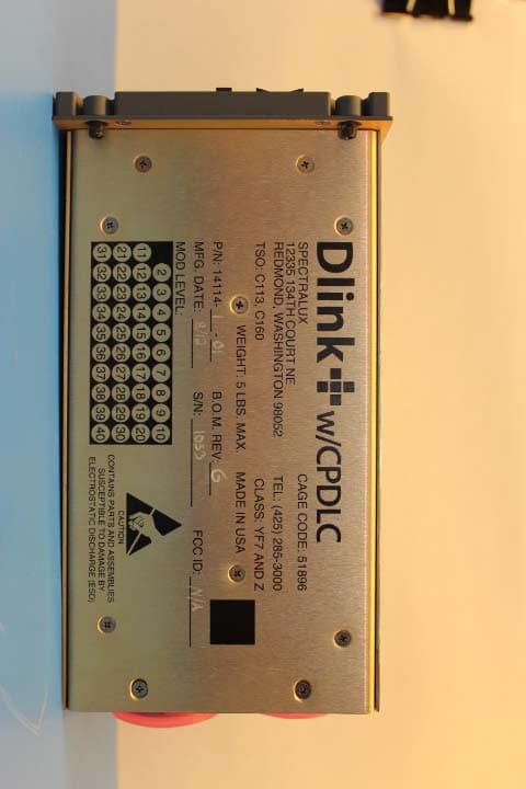
R2H14114
Jan 10, 2013Dlink+ w/CPDLC. All-in-one data communications, CPDLC and ACARS in a single LRU
Equipment Class
TNB - Licensed Non-Broadcast Station Transmitter