R2H14114Dlink+ w/CPDLC. All-in-one data communications, CPDLC and ACARS in a single LRU
Software Development Alternatives, Inc.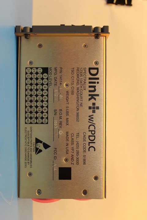
Click to zoom
Application Details
- Equipment Class
- TNB - Licensed Non-Broadcast Station Transmitter
- Date of Grant
- Jan 10, 2013
- Application Purpose
- Original Equipment
- Date of Application
- Jan 06, 2013
- Equipment Note
- Dlink+ w/CPDLC. All-in-one data communications, CPDLC and ACARS in a single LRU
- Frequency Range
- 118.00000000 - 136.97500000
- Country
- United States
Documents & Files
Document Text
Text extracted from the exhibit documents filed with the FCC. Open a document above to read the original.
Users Manual
INST-14114-1 Dlink+ w/CPDLC Installation Manual Document Number: INST-14114-1 Rev. - Page 1 of 25 Installation Manual For Dlink+ w/CPDLC SLC Doc Number INST-14114-1 Revision - 12335 134 th Court NE Redmond, WA 98052 USA Tel: (425) 285-3000 Fax: (425) 285-4200 Email: [email protected] RESTRICTION ON USE, PUBLICATION, OR DISCLOSURE OF PROPRIETARY INFORMATION This document contains information proprietary to Spectralux Corporation, or to a third party to which Spectralux Corporation may have a legal obligation to protect such information from unauthorized disclosure, use, or duplication. Any disclosure, use, or duplication of this document or of any of the information contained herein for other than the specific purpose for which it was disclosed is expressly prohibited, except as Spectralux Corporation may otherwise agree in writing. Preparer: Engineer: Program Manager: Quality Assurance INST-14114-1 Dlink+ w/CPDLC Installation Manual Document Number: INST-14114-1 Rev. - Page 2 of 25 CHANGE RECORD Paragraph Description Of Change Approval/ Date Revision All Initial release L.Sinn 12/19/2011 - SVN 21090 INST-14114-1 Dlink+ w/CPDLC Installation Manual Document Number: INST-14114-1 Rev. - Page 3 of 25 Table of Contents 1 Introduction .......................................................................................................................................... 4 2 Description and Operation .................................................................................................................. 4 3 Prepare for Installation ........................................................................................................................ 6 4 Installation and Test .......................................................................................................................... 10 Appendix A – 14114-1-XX Environmental Qualification Form .............................................................. 25 INST-14114-1 Dlink+ w/CPDLC Installation Manual Document Number: INST-14114-1 Rev. - Page 4 of 25 1 Introduction A. This document provides the information required to install the following Dlink+ w/CPDLC part numbers, including all modification levels: • 14114-1-XX “XX” designates the color of the Dlink+ w/CPDLC with a Keyboard Sub-Assembly (front panel). The only difference is the color of the front panel. Therefore, throughout this document, we refer to the Dlink+ w/CPDLC Part Number simply as 14114-1. The information contained in this document applies to all color variants of the Dlink+ w/CPDLC. B. For required test and repair instructions specific to the Dlink+ w/CPDLC, reference Spectralux Component Maintenance Manual 23-20-02. The instructions and procedures defined in the CMM are necessary to ensure the product operates satisfactorily over its service lifetime. Shop level repair is limited to replacement of Circuit Boards. C. Spectralux Corporation contact information: 12335 134th Court NE, Redmond, WA 98052, USA Telephone: +1 425-285-3000 Fax: +1 425-285-4200 Cage Code: 51896 D. The conditions and tests for TSO approval of this article are minimum performance standards. Those installing this article, on or in a specific type or class of aircraft, must determine that the aircraft installation conditions are within the TSO standards. TSO articles must have separate approval for installation in an aircraft. The article may be installed only according to 14 CFR part 43 or the applicable airworthiness requirements. 2 Description and Operation A. The Dlink+ w/CPDLC provides Aircraft Communication Addressing and Reporting System (ACARS) and Controller Pilot Data Link Communications (CPDLC) message capability in one cockpit mounted Line Replaceable Unit (LRU). The Dlink+ w/CPDLC is a Class 7 transceiver that can be tuned to any 25 kHz channel over the frequency range of 118.000 to 136.975 MHz with a RF output power on all frequencies shall not be less than 10 watts in the air. B. The Dlink+ w/CPDLC works in conjunction with a device called the “Personality Module” mounted separately. The personality module is a serial EEPROM that houses the unit’s configuration and database. When the unit is powered ON, the unit reads the data from the personality module. The configuration information determines the aircraft specific information such as tail number and the hardware configuration (what IO ports are connected and the type of devices connected to those ports). The personality module is attached to the aircraft in which the Dlink+ w/CPDLC is installed and connects to the Dlink+ w/CPDLC when installed on the aircraft via the Dlink+ w/CPDLC 11 pin Mil-Circular connector. Any Dlink+ w/CPDLC that is connected to a given personality module will operate with the same configuration. C. The Dlink+ w/CPDLC is cooled through its case and a rear mounted cooling fan. Under normal operating conditions no additional cooling is required. D. Figure 2-1 is a perspective view of the Dlink+ w/CPDLC. INST-14114-1 Dlink+ w/CPDLC Installation Manual Document Number: INST-14114-1 Rev. - Page 5 of 25 Figure 2-2 - Perspective View of Dink+ (14114-1 shown) E. General Specifications • DZUS Mount 5.75” W x 4.5” H x 8.71” D (14.6 cm W x 11.4 cm H 22.1 cm D) • Weight: 5.1 pounds (2.3 kg) • Operating Temperature: -15°C to +55°C • Short Time Operating Temperature: -40ºC to +70ºC with reduced power output at greater than +55ºC • Storage Temperature: -55°C to +85°C • Environmental: DO-160E F. Inputs • 28 VDC (20.5 – 32.2 VDC), 25 watts standby, 160 watts transmitting • RF (118 – 136.975 MHz) • ARINC 429 Receivers 8 • Discretes 8 • 10 Base-T Ethernet 1 G. Outputs • RF (118 – 136.975 MHz), 10 watts minimum • ARINC 429 Transmitters 4 • Discretes 4 • 10 Base-T Ethernet 1 INST-14114-1 Dlink+ w/CPDLC Installation Manual Document Number: INST-14114-1 Rev. - Page 6 of 25 3 Prepare for Installation A. Installations must be performed per the requirements of FAA Advisory Circular (AC) 43.13-1B and 43.13-2B or later…
Text truncated - open the document above for the full version.
Users Manual
Dlink+CPDLC Users Guide Document Number: UG-14114 Rev. - Page 1 of 201 Dlink+CPDLC Users Guide SLC Doc Number UG-14114 Revision - 12335 134 th Court NE Redmond, WA 98052 USA Tel: (425) 285-3000 Fax: (425) 285-4200 Email: [email protected] RESTRICTION ON USE, PUBLICATION, OR DISCLOSURE OF PROPRIETARY INFORMATION This document contains information proprietary to Spectralux Corporation, or to a third party to which Spectralux Corporation may have a legal obligation to protect such information from unauthorized disclosure, use, or duplication. Any disclosure, use, or duplication of this document or of any of the information contained herein for other than the specific purpose for which it was disclosed is expressly prohibited, except as Spectralux Corporation may otherwise agree in writing. Preparer: Paul Newby 2011.12.31 Engineer: Paul Newby 2011.12.31 Program Manager: Robert W. Bernstein 2011.12.31 Quality Assurance David Cierebiej 2011.12.24 Dlink+CPDLC Users Guide Document Number: UG-14114 Rev. - Page 2 of 201 CHANGE RECORD Paragraph Description Of Change Approval/ Date Revision All Initial release Paul Newby 12/20/2011 - SVN 21123 Dlink+CPDLC Users Guide Document Number: UG-14114 Rev. - Page 3 of 201 Table of Contents Dlink+CPDLC Users Guide ......................................................................................................................... 1 SLC Doc Number UG-14114 ....................................................................................................................... 1 Revision - ..................................................................................................................................................... 1 CHANGE RECORD ...................................................................................................................................... 2 1 Introduction .......................................................................................................................................... 7 1.1 Using the Dlink+ w/CPDLC ........................................................................................................... 8 1.1.1 Basic User Interface ................................................................................................................. 9 1.1.2 Keyboard ................................................................................................................................... 9 1.1.3 Advisories ................................................................................................................................ 11 2 Menu Page Tree ................................................................................................................................. 13 2.1 Menu Parameter Description ...................................................................................................... 14 3 Common Menus ................................................................................................................................. 15 3.1 Splash Screen ............................................................................................................................. 15 3.2 Main Menu ................................................................................................................................... 16 3.3 Main – Flight Information Menu ................................................................................................... 17 3.4 Main – Maintenance Menu .......................................................................................................... 18 3.4.1 Maintenance – Monitor Menu Page 1 ..................................................................................... 19 3.4.2 Maintenance – Monitor Menu Page 2 ..................................................................................... 21 3.4.3 Maintenance – System Control Messages Menu ................................................................... 22 3.4.4 Maintenance – Configuration Maintenance Menu .................................................................. 23 3.4.5 Maintenance - Set UTC Menu ................................................................................................. 24 3.4.6 Maintenance – Fail Status Menu............................................................................................. 25 3.5 Configuration Maintenance Menu ............................................................................................... 26 3.5.1 Configuration Maintenance – Password Menu ....................................................................... 26 3.5.2 Configuration Maintenance – User Edit Menu ........................................................................ 27 3.5.3 Configuration Maintenance – System Edit Menu .................................................................... 27 3.5.4 Configuration Maintenance – Software Versions Menu .......................................................... 27 3.6 User Edit Menu ............................................................................................................................ 28 3.6.1 User Edit – Edit Configuration Menu Page 1 .......................................................................... 28 3.6.2 User Edit – Edit Configuration Menu Page 2 .......................................................................... 29 3.6.3 User Edit – Edit Configuration Menu Page 3 .......................................................................... 30 3.6.4 User Edit – Edit Configuration Menu Page 4 .......................................................................... 32 3.6.5 User Edit – Edit Configuration Menu Page 5 .......................................................................... 33 3.7 User Edit – Addresses Configuration Menu ................................................................................ 34 3.8 User Edit – User Defined Uplinks Menu .................................................................…
Text truncated - open the document above for the full version.
Users Manual
Dlink+CPDLC Users Guide Document Number: UG-14114 Rev. - Page 103 of 201 5 ACARS Messages The following lists show the various message types, by message label, which are supported while the Dlink+ w/CPDLC is operating in the ACARS mode. 5.1 ARINC 618 Formatted Messages Label Description 00 Emergency Situation Report 10-39 User Defined Messages 52 Ground UTC Request 54 Voice Contact Request 57 Alternate Aircrew Initiated Position Report 5R Aircrew Initiated Position Report 5U Weather Request 5Y Aircrew Revision to Previous ETA/Diversion Report 7A Aircrew Initiated Engine Data/Takeoff Thrust Report 7B Aircrew Entered Miscellaneous Message Q0 Link Test Q1 Departure/Arrival Report Q2 Estimated Time of Arrival Report QA OUT/Fuel Report (IATA Airport Code) QB OFF Report (IATA Airport Code) QC ON Report (IATA Airport Code) QD IN/Fuel Report (IATA Airport Code) QE OUT/Fuel/Destination Report (IATA Airport Code) QF OFF/Destination Report (IATA Airport Code) QG OUT/Return IN Report (IATA Airport Code) QH OUT Report (IATA Airport Code) QK Landing Report (IATA Airport Code) QL Arrival Report (IATA Airport Code) QM Arrival Information Report (IATA Airport Code) QN Diversion Report (IATA Airport Code) QP OUT Report (ICAO Airport Code) QQ OFF Report (ICAO Airport Code) QR ON Report (ICAO Airport Code) QS IN Report (ICAO Airport Code) QT OUT/Return IN Report (ICAO Airport Code) Dlink+CPDLC Users Guide Document Number: UG-14114 Rev. - Page 104 of 201 5.2 ARINC 622 Formatted Messages Label Description B1 Request Oceanic Clearance B2 Oceanic Clearance Readback B3 Request Departure Clearance B4 Departure Clearance Readback Downlink B7 Free Text to ATC B9 Request ATIS Report BB Terminal Weather Information for Pilots BC Pushback Clearance Request BD Expected Taxi Clearance Request Dlink+CPDLC Users Guide Document Number: UG-14114 Rev. - Page 105 of 201 6 ACARS Operation The Aircraft Communication Addressing and Reporting System is a digital Datalink system for transmission of short, relatively simple messages between aircraft and ground stations via radio or satellite. ACARS operation is an option on the Dlink+ w/CPDLC. If the option has not been enabled the menus and functions, detailed in this document, will not be available to the user. 6.1 Start up To begin using the ACARS system, assuming the system has been configured with the proper service providers, frequency lists, and aircraft identification, it is necessary to enter in some basic information about the flight. Refer to the Main – Flight Information Menu section for a visual representation of the menus and an explanation of the data contained within. 6.1.1 Entering the Flight Number The flight number is a required data item used as an aid in identifying your aircraft to the various operation and maintenance centers. The flight number will consist of 1-4 numeric characters. The flight number may be entered manually or may be collected from available aircraft information broadcasted over the ARINC 429 busses and populated automatically. 6.1.2 Entering Origin and Destination Stations The origin and destination stations consist of 4 alpha characters. The origin and destinations may be entered manually or may be collected from available aircraft information broadcasted over the ARINC 429 busses and populated automatically. 6.2 Sending a Message Pressing the ACARS function key will bring you directly to the ACARS Index Menu. (see: Figure 3.12.13-1 ACARS Index Menu). From the menu index follow the prompts to the desired message type. Refer to ACARS Menus for specific details. 6.2.1 Requirements for Sending a Message In order to facilitate sending an ACARS messages there must exist a link to the ground through a service provider. When there is no established link the Dlink+ w/CPDLC will report “NO COMM” in the advisory area of the display. The COMM Status may be viewed by pressing the READ Function key. This will display the Monitor Menu, showing the COMM Status and the states of various services (VHF, Satcom, and ATN). 6.3 Reading Received Messages When an ACARS message is received the ACARS annunciator will be lit. At this point pressing the MSG function key will display the Message Log Menu (see ACARS Index – Message Log Menu). Navigate to the particular message to be viewed and press the LSK indicated. Refer to (ACARS Index – Message Log Viewing Menu). Dlink+CPDLC Users Guide Document Number: UG-14114 Rev. - Page 106 of 201 7 CPDLC Operation 7.1 CPDLC Menus 7.1.1 CPDLC – Index Menu The CPDLC INDEX Menu is the primary interface for CPDLC Operation. From this menu, access is provided to the CM Logon Menu (see Section7.1.3), the Request Menu (see Section 7.1.5), the Message Log Menu (see Section 7.1.4), the Report Menu (see Section 7.1.13), and the Free Text Menu (see Section 7.1.2). When configuring any of the possible messages on these menus all required fields must be filled in to get a VERIFY Prompt, This VERIFY Prompt will only be displayed when all required fields have been configured. The fields required will vary depending on the message being configured. This is talked about more specifically in the sections that follow for each type of message that can be configured through sub-menus of the CPDLC INDEX Menu. In addition to providing basic access to other CPDLC Menus, the operator is provided with the option to change the ATN Operational Mode. The ‘ATN Mode’ can be configured to RTCA DO280B or Link 2000. When configured for RTCA DO280B operation, most of the RTCA DO280B defined message set is available for use. When configured for Link2000 Operational mode, the available message set (both uplink and downlink) is limited to those messages supported in the European Link 2000 environment (see Sections 7.3.1 and 7.3.2). The ATN Mode may be toggled between Link 2000 and RTCA DO280B by selecting the L1 Line Select Key on the B-Page of the CPDLC INDEX Menu. Dlink+CPDLC Users Guide Document Number: UG-14114 Rev. - Page 107 of 201 PAGE NAVIGATION: 1. ► CP…
Text truncated - open the document above for the full version.
Cover Letter(s)
Spectralux Corporation 12335 134 th Court NE Redmond, WA 98052 phone: 425.285.3000 fax: 425.285.4200 December 12, 2012 Federal Communications Commission 7435 Oakland Mills Road Columbia, MD 21046 Subject: Request for Permanent Confidentiality To whom it may concern: In accordance with 47CFR Section 0.457 and Section 0.459 pertaining to confidential material, we hereby request to hold permanently confidential all information contained within the below identified exhibits/document categ ories submitted pursuant to radio equipment certification requirements for FCC ID: R2H14114. 1. Block Diagrams 2. Operational Descriptions 3. Schematics 4. Tune‐Up Procedure The above material contains trade secrets and proprietary information as specified by 47CFR 0.457(d) and technical data, which would customarily be guarded from competitors. The public disclosure of this information mi ght be harmful to our company and provide unjustified benefits to our competitors. Sincerely, Robert Bernstein Director of Engineering Spectralux Corporation
Cover Letter(s)
Spectralux Corporation 12335 134 th Court NE Redmond, WA 98052 phone: 425.285.3000 fax: 425.285.4200 December 10, 2012 To Whom It May Concern: We hereby delegate CKC Certification Services, LLC (CKC CS) power of attorney to act on our behalf in matters pertaining to certification of products. The actions of CKC CS shall be considered the same as our own. Sincerely, Michael Burke President
Cover Letter(s)
Spectralux Corporation 12335 134 th Court NE Redmond, WA 98052 phone: 425.285.3000 fax: 425.285.4200 December 10, 2012 To Whom It May Concern: I hereby appoint Michael Burke to sign letters and applications for any filings with regulatory agencies on our behalf, and to receive and exchange data between our company, the agents company and the agency in connection with certification for any products that our company owns or manufactures. Sincerely, Robert Bernstein Director of Engineering Spectralux Corporation
ID Label/Location Info
1 01 G Dlink+ w/CPDLC LABEL INFORMATION MOD LEVELS, DASH NUMBERS,MFG. DATE, B.O.M. REVISIONS AND SERIAL NUMBERS MAY VARY ON THE Dlink+ w/CPDLC MODEL 14114. MODIFICATIONS, REVISIONS AND CHANGES WILL BE REVIEWED AND SUBMITTED FOR APPROVAL PER THE REQUIREMENTS OF 47 CFR 2.1043. R2H14114 09/20111001
Test Report
This report contains a total of 45 pages and may be reproduced in full only. Partial reproduction may only be done with the written consent of CKC Laboratories, Inc. Spectralux Corporation TEST REPORT FOR Dlink+ w/CPDLC, 14114-1-01 Tested To The Following Standards: FCC Part 87 Subpart D Report No.: 91600-10 Date of issue: October 4, 2012 This test report bears the accreditation symbol indicating that the testing performed herein meets the test and reporting requirements of ISO/IEC 17025 under the applicable scope of EMC testing for CKC Laboratories, Inc. We strive to create long-term, trust based relationships by providing sound, adaptive, customer first testing services. We embrace each of our customers’ unique EMC challenges, not as an interruption to set processes, but rather as the reason we are in business. Page 2 of 45 Report No.: 91600-10 TABLE OF CONTENTS Administrative Information ........................................................................................................................................... 3 Test Report Information ............................................................................................................................................ 3 Report Authorization ................................................................................................................................................. 3 Test Facility Information ............................................................................................................................................ 4 Site Registration & Accreditation Information .......................................................................................................... 4 Summary of Results ................................................................................................................................................... 5 Conditions During Testing.......................................................................................................................................... 5 Equipment Under Test ............................................................................................................................................... 6 Peripheral Devices ..................................................................................................................................................... 6 EUT Labels .................................................................................................................................................................. 6 FCC Part 87 .................................................................................................................................................................... 7 87.131 Power and Emissions ..................................................................................................................................... 7 87.133 Frequency Stability ...................................................................................................................................... 10 87.135 Bandwidth of Emissions ............................................................................................................................... 13 87.139 Emissions Limitations................................................................................................................................... 19 Spurious Emissions at Antenna Terminal ............................................................................................................ 19 Field Strength of Spurious Radiation ................................................................................................................... 30 Adjacent Channel Power ..................................................................................................................................... 39 Supplemental Information .......................................................................................................................................... 44 Measurement Uncertainty ...................................................................................................................................... 44 Emissions Test Details .............................................................................................................................................. 44 Page 3 of 45 Report No.: 91600-10 ADMINISTRATIVE INFORMATION Test Report Information REPORT PREPARED FOR: REPORT PREPARED BY: Spectralux Corporation 12335 134th Court NE Redmond, WA 98052 Joyce Walker CKC Laboratories, Inc. 5046 Sierra Pines Drive Mariposa, CA 95338 REPRESENTATIVE: Gary Altman Project Number: 91600 Customer Reference Number: 112583 DATE OF EQUIPMENT RECEIPT: September 17, 2012 DATE(S) OF TESTING: September 17 - 20, 2012 Report Authorization The test data contained in this report documents the observed testing parameters pertaining to and are relevant for only the sample equipment tested in the agreed upon operational mode(s) and configuration(s) as identified herein. Compliance assessment remains the client’s responsibility. This report may not be used to claim product endorsement by A2LA or any government agencies. This test report has been authorized for release under quality control from CKC Laboratories, Inc. Steve Behm Director of Quality Assurance & Engineering Services CKC Laboratories, Inc. Page 4 of 45 Report No.: 91600-10 Test Facility Information Our laboratories are configured to effectively test a wide variety of product types. CKC utilizes first class test equipment, anechoic chambers, data acquisition and information services to create accurate, repeatable and affordable test results. TEST LOCATION(S): CKC Laboratories, Inc. 22116 23rd Drive S.E., Suite A Bothell, WA 98021-4413 Site Registration & Accreditation Information Location CB # TAIWAN CANADA FCC JAPAN Bothell US0081 SL2-IN-E-1145R 3082C-1 318736 R-2296 C-2506 T-1489 G-284 Page 5 of 45 Report No.: 91600-10 SUMMARY OF RESULTS Standar…
Text truncated - open the document above for the full version.
Contact Information
Applicant
Dave Dodson(President)
Technical Contact
Spectralux CorporationRobert Bernstein
[email protected]425-285-3030
12335 134th Court NE · Redmond · United States
Test Firm
CKC Laboratories, Inc.Steve Behm
Technical Specifications
| # | Rule Parts | Frequency Range | Power Output | Emission | Tolerance |
|---|---|---|---|---|---|
| 2 | 87 | 118 MHz - 136.975 MHz | 15.1 W | 13K0A2D | 30 ppm |
Other Applications from Software Development Alternatives, Inc.

R2H13281-1
May 27, 2004VHF Data Link Device
Equipment Class
TNB - Licensed Non-Broadcast Station Transmitter