R2U66ANWNWRWireless Router
Hunan Ocean Wing Ecommerce Limited Company
Click to zoom
Application Details
- Equipment Class
- DTS - Digital Transmission System
- Date of Grant
- Nov 22, 2012
- Application Purpose
- Original Equipment
- Date of Application
- Nov 20, 2012
- Equipment Note
- Wireless Router
- Frequency Range
- 2412.00000000 - 2462.00000000
- Country
- China
Documents & Files
Document Text
Text extracted from the exhibit documents filed with the FCC. Open a document above to read the original.
Users Manual
GW-WR302N 1 1 Mode Introduction 1.1 Bridge Mode In the Bridge mode, GW-WR302N works as a wireless router to achieve wireless connection for the wired LAN. 1.2 Router Mode In the Router mode, GW-WR302N works as a domestic gateway. 1.3 Wireless Universal Repeater/WDS Mode In the Wireless Universal Repeater/WDS mode, GW-WR302N expands wireless coverage of the existing AP. Computers can connect to GW-WR302N in either a wired or wireless way. 1.4 Client Mode In the Client mode, GW-WR302N provides Internet access for a set-top box or a computer with a network adapter. 2 Configuring Your Computer The following takes Window XP as an example. Do as follows to manually set the network adapter: Step 1 Right-click the icon of My Network Places and choose Properties to display the Network Connections window. GW-WR302N 2 Step 2 Right-click the icon of a network interface card or wireless network adapter and choose Properties. (Note: In the Client mode, computers can connect to GW-WR302N through an Ethernet cable only.) Step 3 Double-click Internet Protocol (TCP/IP). Step 4 (1) When GW-WR302N is set to the Router mode, select Obtain an IP address automatically. (2) When GW-WR302N is set to other modes, set the IP address of your computer to 192.168.100.X (X is an integer in the range of 2 to 253), and the MAC address to 255.255.255.0. Set the gateway and the IP address of the DNS server. You can leave them blank if you do not know information about the gateway and DNS server. Click OK. GW-WR302N 3 Note: After you finish configuring GW-WR302N, the domestic gateway can set the Internet protocol for the PC’s network adapter. Set the IP address and DNS server to Obtain an IP address automatically as shown in figure above. 3 Configuring Wireless Connection The following takes Windows XP as an example. Do as follows to connect the wireless network adapter of your PC to GW-WR302N: Step 1 Click the icon displayed at the right bottom corner of the desktop (Note: Ensure that your PC is installed with a wireless network adapter). Step 2 In the Wireless Network Connection page, double-click the desired wireless network. Step 3 Your computer successfully connects to the wireless network when Connected is displayed on the right upper corner. Note: The default SSID of GW-WR302N is GOLDWEB. GW-WR302N 4 4 Logging In to the Web Page When the wireless router is connected to your computer, you can access and configure the router using your browser. Run the Internet Explorer (IE), enter http://192.168.100.254/ (the default IP address of the wireless router) in the address bar, and press Enter. In the window that is displayed as shown in the following figure, set the Language to English, enter the user name and password, and click Login. The default user name and password are admin and admin respectively After logging in to the Web page, you can view, configure and modify the router settings. To make modified settings take effect, you need to reboot the wireless router sometimes. 5 Configuring GW-WR302N 5.1 Bridge Mode Configuration Step 1 Set the three-way switch on the side panel to AP after GW-WR302N is powered on. Log in to the configuration page after the system is started. Step 2 Click Setup Wizard in the navigation bar on the left pane of the page. Set the SSID and encryption password and note them down. Click Finish to complete the settings. GW-WR302N 5 5.2 Router Mode Configuration Step 1 Set the three-way switch on the side panel to AP after GW-WR302N is powered on. Log in to the configuration page after the system is started. Step 2 Click Mode Settings and select Router Mode. (The default mode is Bridge Mode.) Step 3 Connect your PC to GW-WR302N using a wireless network adapter after GW-WR302N is restarted successfully. Log in to the configuration page. Click Setup Wizard in the navigation bar on the left pane of the page. Select Yes and click Next. GW-WR302N will automatically detect the broadband type. Step 4 GW-WR302N can detect three types of broadband: DHCP, Static IP, and PPPoE. Perform configurations according to the broadband type you are using. Parameter configuration for DHCP Parameter configuration for static IP GW-WR302N 6 Parameter configuration for PPPoE Step 5 Click Next. Set the SSID and password and note them down. Click Finish to complete the settings. 5.3 Repeater Mode Configuration Step 1 Set the three-way switch on the side panel to Repeater after GW-WR302N is powered on. Log in to the configuration page after the system is started. Step 2 Click Setup Wizard in the navigation bar on the left pane of the page. Select Wireless Universal Repeater Mode and click Next. GW-WR302N 7 Step 3 Click Site Survey to search for the wireless network you want to connect. Select a desired network. Click Next. Step 4 Configure the repeater with the same security option as its uplink network. (The following figure takes the security option of None as an example.) Set the encryption password and note it down. Click Finish to complete the settings. Step 5 GW-WR302N provides the wireless roaming function if you select Synchronize Wireless Universal Repeater's And Uplink AP's SSID And Security Options. Click Finish to complete setup wizard. GW-WR302N 8 5.4 WDS Mode Configuration 5.4.1 Repeater Configuration in the WDS Mode Step 1 Set the three-way switch on the side panel to Repeater after GW-WR302N is powered on. Log in to the configuration page after the system is started. Step 2 Click Setup Wizard in the navigation bar on the left pane of the page. Select WDS Mode and click Next. (Note: The WDS function cannot be used if the channel is set to Auto) Manually set all WDS devices to the same channel. Step 3 Set the IP address of the LAN port of the repeater and enter the MAC address of the basic station. Click Next. Step 4 Set the SSID, channel, and security encryption for the repeater. The channel cannot be set to Auto. It is recommended to configure the repeater with the same security option as its base station. …
Text truncated - open the document above for the full version.
External Photos
EXTERNAL PHOTOS
ID Label/Location Info
LABEL LOCATION
Internal Photos
INTERNAL PHOTOS Antenna 0 Antenna 1
RF Exposure Info
Maximum Permissible Exposure Compliance Requirement 1. LIMITS The limit for general population/uncontrolled exposures Frequency Power density(mW/cm 2 ) Averaging time(minutes) 300MHz~1.5GHz F/1500 30 1.5GHz~100GHz 1.0 30 Frequency(MHz) Power density(mW/cm 2 ) Averaging time(minutes) 2412 1.0 30 2437 1.0 30 2462 1.0 30 2. EUT RF Exposure The Max Conducted Peak Output Power is 21.55dBm (142.89mW) in channel 11 of 802.11n20; The EUT has two antennas. The max conducted peak output power of antenna 0 is 18.10dBm (64.56mW). The antenna gain of this antenna is 1.6dBi. The max conducted peak output power of antenna 1 is 18.93dBm (78.16mW). The antenna gain of this antenna is 1.8dBi. 1.6dB logarithmic terms convert to numeric result is nearly 1.51. 1.8dB logarithmic terms convert to numeric result is nearly 1.45. According to the formula S= π 2 4R PG ,we can calculate S which is MPE. Now , R=20 cm, P 0 =64.56mW, G 0 =1.45;P 1 =78.16mW, G 1 =1.51. So,S= π 2 4R PG = 4.13*400*4 45.1*56.6451.1*16.78+ =0.042 mW/cm 2 So the MPE comply the requirement.
Test Report
FCC ID R2U66ANWNWR TEST REPORT Report No.: EM201200596-1 Application No.: ZJ00022277 Client: Hunan Ocean Wing Ecommerce Limited Company Address: Room 2301, Best-one Metro Building, No.359 Furong Middle Road, Yuhua District, Changsha, Hunan Sample Description: Compact WI-FI Repeater Model: 66ANWNWR Adding model / FCC ID: R2U66ANWNWR Test Specification: FCC Part 15,Subpart C(Section 15.247) Test Date: 2012-11-05 to 11-09 Issue Date: 2012-11-09 Test Result: Pass. Prepared By: Reviewed By: Approved By: Lynn Xiao/ Test Engineer Jane Cao / Technical Assistance Gavin Wu / Manager Date:2012-11-09 Date:2012-11-09 Date:2012-11-09 Other Aspects: / Abbreviations: ok / P = passed; fail / F = failed; n.a. / N = not applicable The test result in this test report refers exclusively to the presented test sample. This report shall not be reproduced except in full, without the written approval of GRGT. GRG Metrology and Test Co., Ltd. Address: 163, Pingyun Road, West of Huangpu Avenue, Guangzhou, Guangdong, P.R. China Tel:+86-20-38699960 Fax:+86-20-38695185 Email: [email protected] http://www.grgtest.com Ver.:1.0 / 01.Jan.2011 Report No.: EM201200596-1 Application No.: ZJ00022277 Page 2 of 136 FCC ID R2U66ANWNWR DIRECTIONS OF TEST 1. This station carries out test task according to the national regulation of verifications which can be traced to National Primary Standards and BIPM. 2. The test report merely corresponds to the test sample. It is not permitted to copy extracts of these test result without the written permission of the test laboratory. 3. If there is any objection concerning the test, the client should inform the laboratory within 15 days from the date of receiving the test report. Report No.: EM201200596-1 Application No.: ZJ00022277 Page 3 of 136 FCC ID R2U66ANWNWR Table of Contents TABLE OF CONTENTS .......................................................................................................................................................... 3 1. TEST RESULT SUMMARY ............................................................................................................................................... 4 2. GENERAL DESCRIPTION OF EUT ................................................................................................................................. 5 2.1 APPLICANT .................................................................................................................................................................... 5 2.2 MANUFACTURER ......................................................................................................................................................... 5 2.3 BASIC DESCRIPTION OF EQUIPMENT UNDER TEST ............................................................................................. 5 3. LABORATORY AND ACCREDITATIONS ..................................................................................................................... 6 3.1 LABORATORY ............................................................................................................................................................... 6 3.2 ACCREDITATIONS ........................................................................................................................................................ 6 3.3 MEASUREMENT UNCERTAINTY ............................................................................................................................... 6 3.4 LIST OF USED TEST EQUIPMENT AT GRGT ............................................................................................................. 7 4. ANTENNA REQUIREMENT ............................................................................................................................................. 8 5. CONDUCTED EMISSION MEASUREMENT ................................................................................................................. 9 5.1 LIMITS ......................................................................................................................................................................... 9 5.2 TEST PROCEDURES .................................................................................................................................................. 9 5.3 TEST SETUP ............................................................................................................................................................. 10 5.4 TEST RESULTS ......................................................................................................................................................... 11 6. RADIATED ELECTROMAGNETIC DISTURBANCE ................................................................................................. 13 6.1 LIMITS ....................................................................................................................................................................... 13 6.2 TEST PROCEDURES ................................................................................................................................................ 13 6.3 TEST SETUP ............................................................................................................................................................. 14 6.4 TEST RESULTS ......................................................................................................................................................... 16 7. SPURIOUS EMSSION AT ANTENNA PORT ................................................................................................................ 40 7.1 LIMITS ....................................................................................................................................................................... 40 7.2 TEST PROCEDURES ................................................................................................................................................ 40 7.3 TEST…
Text truncated - open the document above for the full version.
Test Setup Photos
TEST SETUP PHOTOS
Contact Information
Applicant
Jessica Li(Purchaser)
Technical Contact
GUANGZHOU GRG METROLOGY&TEST CO.,LTD.Angel Liu
[email protected]86-20-39699960-341
163 Ping Yun Rd,West of HuangPu Ave, · Guangzhou · China
Test Firm
Guangzhou GRG Metrology And Test Technology LTD.Huang Yingling
Technical Specifications
| # | Rule Parts | Frequency Range | Power Output |
|---|---|---|---|
| 1 | 15C | 2.41 GHz - 2.46 GHz | 142.89 mW |
Other Applications from Hunan Ocean Wing Ecommerce Limited Company
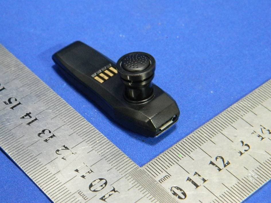
R2U99ANHDSET-BSA
Aug 04, 2013Bluetooth Headset
Equipment Class
DSS - Part 15 Spread Spectrum Transmitter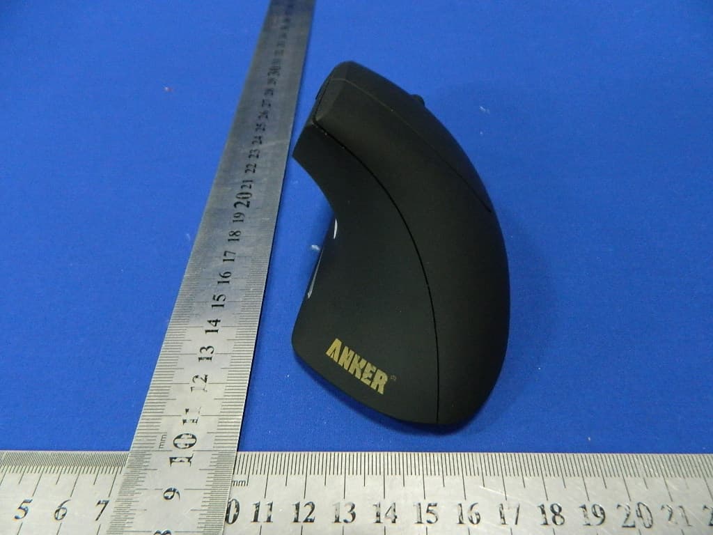
R2U-TM137G
Jun 09, 20132.4G wireless optical mouse
Equipment Class
DXX - Part 15 Low Power Communication Device Transmitter