R2U99ANHDSET-BSABluetooth Headset
Hunan Ocean Wing Ecommerce Limited Company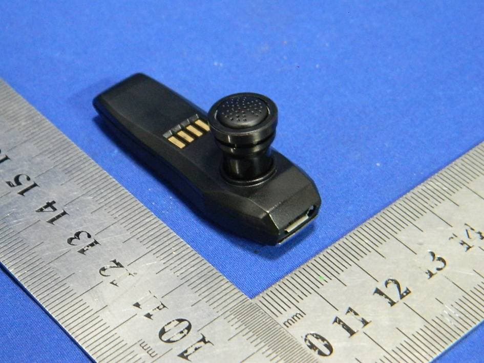
Click to zoom
Application Details
- Equipment Class
- DSS - Part 15 Spread Spectrum Transmitter
- Date of Grant
- Aug 04, 2013
- Application Purpose
- Original Equipment
- Date of Application
- Aug 04, 2013
- Equipment Note
- Bluetooth Headset
- Frequency Range
- 2402.00000000 - 2480.00000000
- Country
- China
Documents & Files
Document Text
Text extracted from the exhibit documents filed with the FCC. Open a document above to read the original.
Users Manual
Anker® Bluetooth Headset (with Charging Dock) The Anker® Bluetooth Headset gives you the freedom to take calls on the road hands‐free, letting you stay connected without the dangers of one‐handed stearing. Not taking a call? Enjoy music or media streaming from your Bluetooth‐enabled devices to pass the time. With its compact size and flexible functionality, the Anker® Bluetooth Headset is an indispensable companion on the road or wherever your journey takes you. Package Contents Headset Charging dock 2 ear hooks 2 eartips A dhesive mounting strip Vehicle air vent mounting clip USB charing cable Manual Specifications Bluetooth Version 2.1+EDR Supported Bluetooth Profiles HSP, HFP, A2DP Operational Range 10m / 32.8ft Talk / Play Time Approximately 5 hours Charge Time Approximately 2 hours Dimensions (Headset) 55 x 18 x 25mm / 2.2 x 0.7 x 1.0in Dimensions (Dock) 40 x 26 x 33mm / 1.6 x 1.0 x 1.3in Weight (Headset) 7g / 0.25oz Weight (Dock) 15g / 0.53oz Identification of Parts Answer/end button Volume up button Volume down button Headset micro USB input port Charging dock micro USB input port Headset LED indicator Charging dock LED indicator How to mount the charging dock with the adhesive mounting strip Peal the back off the adhesive strip. 1. Place firmly onto the the dash or another suitable mounting position. 2. Connect the charging dock to the mounting strip. How to mount the charging dock with the vehicle air vent mounting clip Attach the vehicle air vent mounting clip to your vehicle’s air vent. 1. Connect the charging dock to the mounting clip. How to Charge the Anker Bluetooth Headset When the battery is low, the red LED indicator on the headset will begin to flash and the headset’s voice prompt will announce “battery low”. There are two ways to charge the headset: A. Plug the micro USB end of the cable provided into the input port on the headset, then plug the other end into an active USB port. A constant red LED light will indicate the headset is charging. The LED will go off when it is fully charged. B. Plug the micro USB end of the cable provided into the input port on the charging dock, then plug the other end into a charging adapter or an active USB port. The LED indicator on the charging dock will turn yellow indicating it is properly connected to a power source. Place the headset on the charging dock. A constant red LED on the headset will indicate it is charging. The LED will go off when it is fully charged. Basic Operation Turn the headset on Press the answer/end button on the headset once, the blue LED indicator on the headset will flash once every 5 seconds indicating the headset is on. Turn the headset off Press the answer/end button for 3 to 5 seconds until the red LED indicator flashes, and the headset’s voice prompt announces “power off”. Pairing To use y our headset, you must first pair it with your Bluetooth enabled mobile phone. 1. Make sure that the headset is turned off (see “Turn the headset off” above), and the Bluetooth function of your mobile phone is activated. 2. Press and hold the answer/end button for 7 seconds until the indicator alternatively flashes blue and red, and the headset’s voice prompt announces “pairing”. The headset is now in pairing mode. 3. Search for the headset on your mobile phone until the it finds “Anker LS141” and asks if you want to pair with it. Confirm the pairing by pressing “yes” on your mobile phone. 4. When the mobile phone connects successfully, the headset’s voice prompt will announce “connected”. Note: If the Bluetooth version of your mobile phone is below version 2.1, you need to enter the password “0000” on your mobile phone to complete the pairing process. IMPORTANT: If the pairing process is not completed with in 90 seconds, the pairing process may not have been successful. Try repeating the steps above. Pairing your headset with two mobile phones (multi‐point connecting) 1. Follow the instructions in the “pairing” section to pair the headset with the first mobile phone. 2. Turn off the headset. 3. Repeat the same pairing procedure for the second mobile phone. 4. Connect the Bluetooth headset to the first mobile phone. The Bluetooth headset is now connected to both mobile phones. Unpairing devices Press and hold the volume up and volume down buttons at the same time for 4 seconds or until the indicator LED flashes blue and red alternatively to delete all paired devices. Sleep mode To make the headset enter sleep mode, p ut the headset on the charging dock, the red LED indicator on the headset will flash once (or, if the charging dock is connected to a power source, it will begin charging), indicating the headset is in sleep mode. To exit sleep mode, take the headset off the charging dock. The blue LED indicator on the headset will flash, indicating the headset is automatically connecting with the paired mobile phone(s). Answering a call When connected to one mobile phone: While the headset is connected, press the answer/end button once to answer a call. If the headset is on the charging dock, pick the headset up off the charging dock to answer a call after it has been ringing for 5 seconds or more. When connected to the first mobile phone and the second mobile phone has an incoming call: 1. When the second mobile phone rings: a. Press the answer/end button once to answer the second call, and keep the current call on hold. b. Press the answer/end button for 2 seconds to reject the second call, and continue with the first call. 2. When the second call is kept: Press answer/end button once to end the first call, and continue with the second call. Ending a call Press the answer/end button once to end a call. Rejecting an incoming call Press and hold the answer/end button for 2 seconds to reject a call. Voice Dialing Please ensure your mobile phone supports voice dialing and voice tags are assigned to your contacts to use this feature. 1. Press the answer/end button once and when you hear the voice prompt announce “voice dial…
Text truncated - open the document above for the full version.
Cover Letter(s)
775 Montague Expressway Milpitas, CA 95035 Tel: 408-526-1 1 88 Fax: 408-526-1 088 Email: [email protected] Project and Product Representative Authorization Letter Reason for Amendment (current / obsolete) Revision Historv Approved Date From Initial Release (obsolete) Revised wordinq bbsolete) Updated company temprlate (current) SCS-FI8: Project and Product Certification Representative Authorization Letter Page I of 2 Rev 3.0 Hlunarr Ocean Wing Ecommerce Limited Company 20t3-7-20 To: SIEMIC, n{C. 7 7 5 Montague Expressway, Milpitas, CA 95035 USA Dear Sir/Madarr, Re: Project and Product Certification Representative Authorization Letter We, Hunan Ocean Wing Ecommerce Limited Company hereby authorize SIEMIC, INC. to act as a Certification Body for certifuing for the following project(s): FCC ID: R2U99ANHDSET-BSA (Bluetooth Hearlset MODEL No. : SSANHDSET-BSA) We affirm that between SIEMIC and Hunan Ocean Wing Ecommerce Limited Company, any difference in understanding, including test plan, measurement methods, applicable standards and relevant procedures and processes have been resolved prior to commencement of testine activities. Sincerely, Jooe'li s/r'l] Jessica Lil Purchaser E-mail: [email protected] Phone: 0731-88709579 Fax: 0731-8870957E Address: Room 23\l,Best-one Metro Building, No.359 Furong Changsha, Hunan Province, China. SCS-F18: Project and Product Certification Representative Authorization Letter Page2 of 2 Rev 3.0
Cover Letter(s)
Confidentiality Request Letter Hunan Ocean Wing Ecommerce Limited Company 20t3-7-20 To: Federal Communications Commission Office of Engineering and Tenhnology Equipment Authorization Division 7345 Oakland Mills Road Columbia, Maryland 21046 Subject: Permanent Confidentiality Request for FCC ID: R2USSANHDSET-BSA We hereby requLest confidential treatment of information accompanying this application as outlined below: - Block driagram - Operationdescription - Schematic The above materials contain trade secrets and proprietary information not customarily released to the public, The public disclosure of these materials may be harmful to the applicant and provide unjustified benefits to its competitors, The applicant understands that pursuant to Section 0,457 & 0.459 of the Rules, disclosure of this application and all accompanying documentation will not be made before the date of the Grant for this application. Jessica Lil Purchaser E-mail: [email protected] Phone: 0731-88709579 Fax: 0731-88709578 Address: Room 2301, Best-one Metro tsuilding, No.359 Furong Changsha, Hunan Province. China.
ID Label/Location Info
Label Location
ID Label/Location Info
ID Label Bluetooth Headset FCC ID: R2U99ANHDSET-BSA Model Number: 99ANHDSET-BSA Made in Chi na
Internal Photos
BT module Antenna
RF Exposure Info
FCC ID: R2U99ANHDSET-BSA Portable device According to §15.247(e)(i) and §1.1307(b)(1), systems operating under the provisions of this section shall be operated in a manner that ensures that the public is not exposed to radio frequency energy level in excess of the Commission’s guidelines. According to KDB447498 D01 General RF Exposure Guidance V05 The 1-g and 10-g SAR test exclusion thresholds for 100 MHz to 6 GHz at test separation distances ≤ 50 mm are determined by: [(max. power of channel, including tune-up tolerance, mW)/(min. test separation distance, mm)] * [√f(GHz)] ≤ 3.0 for 1-g SAR and ≤ 7.5 for 10-g extremity SAR, where f(GHz) is the RF channel transmit frequency in GHz; Power and distance are rounded to the nearest mW and mm before calculation; The result is rounded to one decimal place for comparison; The test exclusions are applicable only when the minimum test separation distance is ≤ 50 mm and for transmission frequencies between 100 MHz and 6 GHz. When the minimum test separation distance is < 5 mm, a distance of 5 mm is applied to determine SAR test exclusion. We use 5mm as separation distance to calculate. Maximum measured transmitter power: Transmit Frequency (GHz) Mode Max Conducted Power (dBm) Result calculation 1-g SAR 2.441 Bluetooth 7.05 1.58 3.0 Conclusion: For the max result : 1.58≤ 3.0 for 1-g SAR extremity SAR, No SAR is required.
Test Report
TRF No:FCC 15.247/A Page 1 of 52 Report No: ES130629266E Shenzhen EMTEK Co.,Ltd. Building 69, Majialong Industry Zone, Nanshan District, Shenzhen,Guangdong,China www.emtek.com.cn Tel: +86-755-2695 4280 Fax: +86-755-2695 4282 Access to the World ELECTROMAGNETIC EMISSIONS COMPLIANCE REPORT INTENTIONAL RADIATOR CERTIFICATION TO FCC PART 15 SUBPARTC REQUIREMENT OF Bluetooth Headset MODEL No.: 99ANHDSET-BSA FCC ID: R2U99ANHDSET-BSA Trademark: N/A REPORT NO: ES130629266E ISSUE DATE: July 18, 2013 Prepared for Hunan Ocean Wing Ecommerce Limited Company Room 2301, Best-one Metro Building, No.359 Furong Changsha, Hunan Province, China. Prepared by SHENZHEN EMTEK CO., LTD. Bldg 69, Majialong Industry Zone, Nanshan District, Shenzhen, Guangdong, China TEL : 86-755-26954280 FAX: 86-755-26954282 TRF No:FCC 15.247/A Page 2 of 52 Report No: ES130629266E Shenzhen EMTEK Co.,Ltd. Building 69, Majialong Industry Zone, Nanshan District, Shenzhen,Guangdong,China www.emtek.com.cn Tel: +86-755-2695 4280 Fax: +86-755-2695 4282 Access to the World VERIFICATION OF COMPLIANCE Applicant: Hunan Ocean Wing Ecommerce Limited Company Room 2301, Best-one Metro Building, No.359 Furong Changsha, Hunan Province, China. Hunan, China Manufacturer: Hunan Ocean Wing Ecommerce Limited Company Room 2301, Best-one Metro Building, No.359 Furong Changsha, Hunan Province, China. Hunan, China Product Description: Bluetooth Headset Model Number: 99ANHDSET-BSA Serial Number: N/A File Number: ES130629266E Date of Test: July 16, 2013 to July 17, 2013 We hereby certify that: The above equipment was tested by SHENZHEN EMTEK CO., LTD. The test data, data evaluation, test procedures, and equipment configurations shown in this report were made in accordance with the procedures given in ANSI C63.4 (2009) and the energy emitted by the sample EUT tested as described in this report is in compliance with conducted and radiated emission limits of FCC Rules Part 15.247. The test results of this report relate only to the tested sample identified in this report. Date of Test : July 16, 2013 to July 17, 2013 Prepared by : Jack.Li/Editor Reviewer : June xie/Supervisor Approve & Authorized Signer : Lisa Wang/Manager TRF No:FCC 15.247/A Page 3 of 52 Report No: ES130629266E Shenzhen EMTEK Co.,Ltd. Building 69, Majialong Industry Zone, Nanshan District, Shenzhen,Guangdong,China www.emtek.com.cn Tel: +86-755-2695 4280 Fax: +86-755-2695 4282 Access to the World Ta b l e o f C o n t e n t s 1 GENERAL INFORMATION ................................................................................................. 5 1.1 PRODUCT DESCRIPTION........................................................................................................................... 5 1.2 RELATED SUBMITTAL(S) / GRANT (S) ..................................................................................................... 5 1.3 TEST METHODOLOGY.............................................................................................................................. 5 1.4 SPECIAL ACCESSORIES............................................................................................................................ 5 1.5 EQUIPMENT MODIFICATIONS.................................................................................................................. 5 1.6 TEST FACILITY........................................................................................................................................ 6 2 SYSTEM TEST CONFIGURATION .................................................................................... 7 2.1 EUT CONFIGURATION............................................................................................................................. 7 2.2 EUT EXERCISE........................................................................................................................................ 7 2.3 TEST PROCEDURE.................................................................................................................................... 7 2.4 LIMITATION............................................................................................................................................. 7 2.5 CONFIGURATION OF TESTED SYSTEM................................................................................................... 11 2.6 EQUIPMENT USED IN TESTED SYSTEM..................................................................................................... 11 2.7 DESCRIPTION OF TEST MODES................................................................................................................ 12 3 SUMMARY OF TEST RESULTS ............................................................................................... 13 4 CONDUCTED EMISSIONS TEST ..................................................................................... 14 4.1 MEASUREMENT PROCEDURE:................................................................................................................ 14 4.2 TEST SET-UP (BLOCK DIAGRAM OF CONFIGURATION) ....................................................................... 14 4.3 MEASUREMENT EQUIPMENT USED: ...................................................................................................... 14 4.4 CONDUCTED EMISSION LIMIT.................................................................................................................. 14 4.5 MEASUREMENT RESULT:....................................................................................................................... 15 5 RADIATED EMISSION TEST ............................................................................................ 16 5.1 MEASUREMENT PROCEDURE................................................................................................................. 16 5.2 TEST SET-UP (BLOCK DIAGRAM OF CONFIGURATION) ....................................................................... 17 5.3 MEASUREMENT EQUIPMENT USED: ...................…
Text truncated - open the document above for the full version.
Test Setup Photos
PHOTOGRPHS OF TEST SETUP Radiated emission Conducted emission
Contact Information
Applicant
Jessica Li(Purchaser)
Test Firm
EMTEK (Shenzhen) Co., Ltd.David Lee
Technical Specifications
| # | Rule Parts | Frequency Range | Power Output |
|---|---|---|---|
| 1 | 15C | 2.40 GHz - 2.48 GHz | 5.10 mW |
Other Applications from Hunan Ocean Wing Ecommerce Limited Company
R2U-TM137G
Jun 09, 20132.4G wireless optical mouse
Equipment Class
DXX - Part 15 Low Power Communication Device Transmitter
R2U66ANWNWR
Nov 22, 2012Wireless Router
Equipment Class
DTS - Digital Transmission System