R3Y-STSS-ST001SmartTag with Presence, Temperature and Accelerometer
SmartThings, Inc.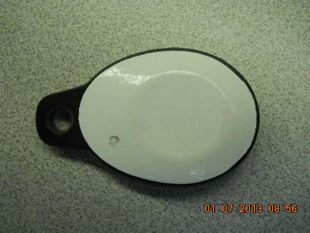
Click to zoom
Application Details
- Equipment Class
- DTS - Digital Transmission System
- Date of Grant
- Jan 27, 2013
- Application Purpose
- Original Equipment
- Date of Application
- Jan 27, 2013
- Equipment Note
- SmartTag with Presence, Temperature and Accelerometer
- Frequency Range
- 2415.00000000 - 2475.00000000
- Company
- SmartThings, Inc.
- Country
- United States
Documents & Files
Document Text
Text extracted from the exhibit documents filed with the FCC. Open a document above to read the original.
Users Manual
SmartThings Manual Welcome Hi, and thanks for joining the SmartThings family. Please make sure you followed the Getting Started steps in your kit. This user manual will give you some additional info on the different SmartThings you may have in your SmartThings Kit. If you have any questions at all, simply boot up your mobile app to talk to us directly or go to www.smartthings.com. Meet Your SmartThings Depending on your SmartThings Kit, you may have a few different SmartThings. They include: (WITH IMAGES AND CORRESPONDING MOBILE ICON SmartSense Open/Closed – Provides open and closed status notification when installed on a door, window, cabinet, drawer or anywhere the two components of the contact sensor can be brought together or pulled apart. SmartSense Motion – Detects Infrared (IR) Motion from large animals and people when they enter the field of vision of the device. SmartSense Presence – Detects if the holder of the device is within range of the SmartThings Hub. Has a small speaker for identifying lost items (like keys or the pet’s collar). SmartSense Multi – Can detect angle in 3 axis, vibration, movement and temperature. SmartTag – Combines the SmartSense Presence with the SmartSense Multi into one device. Getting Around Let’s take a look at each device. IMAGES WITH CALL OUTS FOR EACH SmartSense Open/Closed (and Multi) – Magnet location (both sides). How to take off the back. Access to batteries. Pairing button. SmartSense Motion – IR sensor location. Micro-USB power location. How to take off the back and install batteries. Pairing button. SmartSense Presence (and SmartTag) – Rubber ring. Battery access. Pairing button. Installation SmartThings work best if they are installed close by (within 50 feet) of the SmartThings Hub, or have a pluggable SmartThing (SmartSense Motion, SmartPower Outlet) in between the SmartThings Hub and the device. In all cases, follow the getting started experience in the SmartThings mobile application for instructions on how to pair your SmartThings to your SmartThings Hub and for advice on installation. To pair a SmartThings device to the SmartThings Hub, at the location of the Hub press the ( + ) button, press Add SmartThings, and then press the button on the SmartThing device one time quickly. You will see the LED flash. To factory reset a SmartThing device in the event you want to add it to a new SmartThings Hub, press and hold the button for 6 seconds. You will see the LED flash. Each SmartThings devices has its own power requirement. On first receipt, the batteries may be inserted but will have a barrier that needs to be removed before use. SmartSense Open/Closed (and Multi) – 2 x AAAA batteries. SmartSense Motion – Either 2 x AA batteries or pluggable via micro-USB. SmartSense Presence (and SmartTag) – 1 x CR2032 coin cell battery. Certifications Certified under FCC Part 15 Certified in Canada by IC to RSS-210 This Class B digital apparatus complies with Canadian ICES-003 Cet appareil numérique de la classe B est conforme à la norme NMB-003 du Canada. SmartSense Presence FCC ID: R3Y-STSS-ST001, M/N: STSS-PRES- 001,IC: 10734A-STSSST001 SmartTag FCC ID: R3Y-STSS-ST001, M/N: STSS-ST-001, IC: 10734A- STSSST001 SmartSense Open/Closed, SmartSense Multi and and SmartSense Motion contain FCC ID: W7Z-ZICM357SP2, M/N: ZICM357SP2-1, IC: 8254A-ZICM357SP2 FCC Statement Operations of this device is subject to the following two conditions: (1) this device may not cause interference, and (2) this device must accept any interference, including interference that may cause undesired operation of the device. Canada Statement This device complies with Industry Canada license-exempt RSS standard(s). Operation is subject to the following two conditions: (1) this device may not cause interference, and (2) this device must accept any interference, including interference that may cause undesired operation of the device. Le present appareil est conforme aux CNR d'Industrie Canada applicables aux appareils radio exempts de licence. L’exploitation est aurorisee aux deux conditions suivantes: (1) l’appareil ne doit pas pas produire de brouillage, et (2) l’utilisateur de l’appareil doit accepter toute brouillage radioelectrique subi, meme si le brouillage est susceptible d’en compromettre le fonctionnement. Information to the user: Changes or modifications not expressly approved by Physical Graph Corporation could void your authority to operation the equipment. This equipment has been tested and found to comply with the limits for a Class B digital device, pursuant to Part 15 of the FCC Rules. These limits are designed to provide reasonable protection against harmful interference in a residential installation. This equipment generates and can radiate radio frequency energy and, if not installed and used in accordance with the instructions, may cause harmful interference to radio communications. However, there is no guarantee that interference will not occur in a particular installation. If this equipment does cause harmful interference to radio or television reception, which can be determined by turning the equipment off and on, the user is encouraged to try to correct the interference by one or more of the following measures: Reorient or relocate the receiving antenna. Increase the separation between the equipment and the receiver. Connect the equipment to an outlet on a circuit different from that to which the receiver is connected. Consult the dealer or an experience radio/TV technician for help. Important Safety Instructions 1. Read, keep and follow these instructions 2. Heed all warnings. 3. Do not use this product near water or expose the product to dripping or splashing of any water or liquid. 4. Clean only with a dry cloth. 5. Do not install near any heat sources such as radiators, heat registers, stovers or other apparatus (including amplifiers) that produce heat 6. Protect the power cord from being walked on or pinched, particularly at plugs and wher…
Text truncated - open the document above for the full version.
ID Label/Location Info
1 PROPRIETARY AND CONFIDENTIAL THE INFORMATION CONTAINED IN THIS DRAWING IS THE SOLE PROPER OF SMARTTHINGS. ANY REPRODUCTION IN PART OR AS A WHOLE WITHOUT THE WRITTEN PERMISSION OF SMARTTHINGS IS PROHIBITED. NA 0.95 in 0.2 in smartThings - Smart Tag Sheet 1 0f 1 DOC NAME REV NOTES SCALE Dec. 18, 2012 smartThings_SmartTag.ai TBD Satin Waterproof Finish WA DAT E DESIGNERMATERIAL FINISH 1:1 Part No. 0000-000 Smart Tag Opposite Side Label Location Not to Scale TWO PLACE DECIMAL .01 THREE PLACE DECIMAL .005 DIMENSIONS ARE IN INCHES DO NOT SCALE DRAWING M/N: STSS-ST-001 FCC ID: R3Y-STSS-ST001 IC ID:10734A-STSSST001 made in USA Die Line
ID Label/Location Info
Sheet 1 0f 1 Label Location Not to Scale Part No. 0000-000 Smart Tag Opposite Side 1 PROPRIETARY AND CONFIDENTIAL THE INFORMATION CONTAINED IN THIS DRAWING IS THE SOLE PROPER OF SMARTTHINGS. ANY REPRODUCTION IN PART OR AS A WHOLE WITHOUT THE WRITTEN PERMISSION OF SMARTTHINGS IS PROHIBITED. NA 0.95 in 0.2 in smartThings - Smart Tag DOC NAME REV NOTES SCALE Dec. 18, 2012 smartThings_SmartTag.ai TBD Satin Waterproof Finish WA DAT E DESIGNERMATERIAL FINISH 1:1 TWO PLACE DECIMAL .01 THREE PLACE DECIMAL .005 DIMENSIONS ARE IN INCHES DO NOT SCALE DRAWING M/N: STSS-ST-001 FCC ID: R3Y-STSS-ST001 IC ID:10734A-STSSST001 made in USA Die Line
Test Report
Engineering Test Report No. 1203819-01 Measurement of RF Emissions from a CD305 Smart Tag Transmitter For Physical Graph Corporation 11654 Plaza America Drive Reston, VA 20190 P.O. Number Credit Card Date Tested November 13 -14, 2012 Test Personnel Richard King Test Specification FCC "Code of Federal Regulations" Title 47, Part 15, Subpart C, Section 15.247 for Frequency Hopping Spread Spectrum Intentional Radiators or Digital Modulation Intentional Radiators Operating within The 2400-2483.5MHz band Test Report By: Richard King EMC Engineer Requested By: Andrew Sterian Physical Graph Corporation Approved By: Raymond J. Klouda Registered Professional Engineer of Illinois - 44894 Elite Electronic Engineering, Inc. 1516 Centre Circle Downers Grove, IL 60515 Tel : (630) 495-9770 Fax: (630) 495-9785 www.elitetest.com Engineering Test Report No. 1203819-01 TABLE OF CONTENTS PARAGRAPH DESCRIPTION OF CONTENTS PAGE NO. THIS REPORT SHALL NOT BE REPRODUCED, EXCEPT IN FULL, WITHOUT THE WRITTEN APPROVAL OF ELITE ELECTRONIC ENGINEERING INCORPORATED. Page 2 of 58 1. Introduction ................................................................................................................................................... 5 1.1. Scope of Tests ..................................................................................................................................... 5 1.2. Purpose ............................................................................................................................................... 5 1.3. Deviations, Additions and Exclusions .................................................................................................. 5 1.4. EMC Laboratory Identification ............................................................................................................. 5 1.5. Laboratory Conditions.......................................................................................................................... 5 2. Applicable Documents .................................................................................................................................. 5 3. EUT Setup and Operation ............................................................................................................................ 5 3.1. General Description ............................................................................................................................. 5 3.1.1. Power Input ................................................................................................................................. 5 3.1.2. Peripheral Equipment ................................................................................................................. 6 3.1.3. Signal Input/Output Leads .......................................................................................................... 6 3.1.4. Grounding ................................................................................................................................... 6 3.2. Operational Mode ................................................................................................................................ 6 3.3. EUT Modifications ................................................................................................................................ 6 4. Test Facility and Test Instrumentation ......................................................................................................... 6 4.1. Shielded Enclosure .............................................................................................................................. 6 4.2. Test Instrumentation ............................................................................................................................ 6 4.3. Calibration Traceability ........................................................................................................................ 6 4.4. Measurement Uncertainty ................................................................................................................... 6 5. Test Procedures ........................................................................................................................................... 7 5.1. 6dB Bandwidth ..................................................................................................................................... 7 5.1.1. Requirement................................................................................................................................ 7 5.1.2. Procedures .................................................................................................................................. 7 5.1.3. Results ........................................................................................................................................ 7 5.2. Output Power ....................................................................................................................................... 7 5.2.1. Requirements .............................................................................................................................. 7 5.2.2. Procedures .................................................................................................................................. 7 5.2.3. Results ........................................................................................................................................ 7 5.3. Radiated Spurious Emissions Measurements ..................................................................................... 8 5.3.1. Requirements .............................................................................................................................. 8 5.3.2. Procedures .................................................................................................................................. 8 5.3.3. Results .....................................................................…
Text truncated - open the document above for the full version.
Test Setup Photos
Engineering Test Report No. 1203819-01 Page 15 of 58 Figure 2 Test Setup for Radiated Emissions, Above 1GHz – Horizontal Polarization Test Setup for Radiated Emissions, Above 1GHz – Vertical Polarization
Contact Information
Applicant
Andrew Brooks(Chief Operating Officer)
Test Firm
Elite Electronic Engineering Inc.Kevin Halpin
Technical Specifications
| # | Rule Parts | Frequency Range | Power Output |
|---|---|---|---|
| 1 | 15C | 2.42 GHz - 2.48 GHz | 17.30 mW |
Other Applications from SmartThings, Inc.
R3Y-STH-ETH200
Mar 29, 2015Home Automation Gateway
Equipment Class
DTS - Digital Transmission System
R3Y-STH-ETH011
Dec 07, 2014The SmartThings Hub is a ZigBee/Z-Wave home automation gateway
Equipment Class
DTS - Digital Transmission System
R3Y-STH-ETH001
Jan 27, 2013SmartThings Hub
Equipment Class
DXX - Part 15 Low Power Communication Device Transmitter