R4HAWXCVB800XCVB 800MHZ
AirWalk Communications, Inc.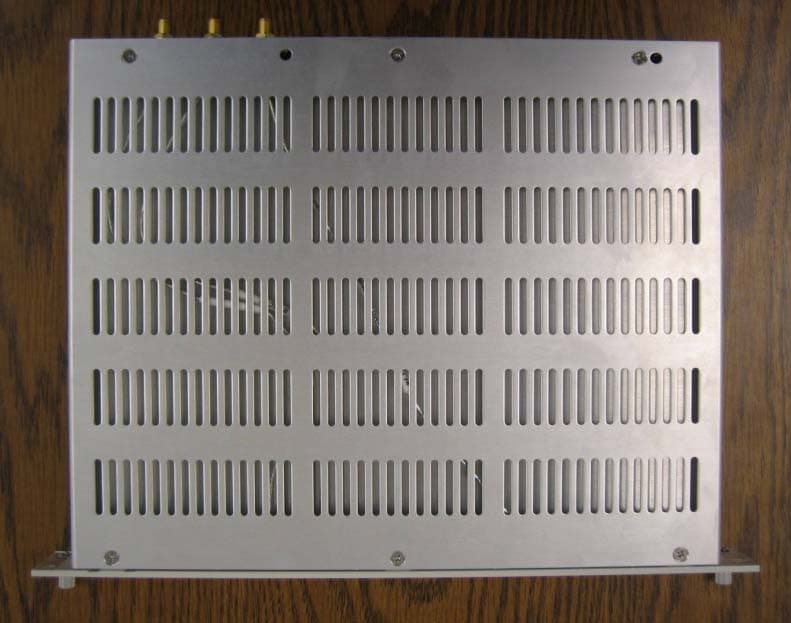
Click to zoom
Application Details
- Equipment Class
- TNB - Licensed Non-Broadcast Station Transmitter
- Date of Grant
- Mar 06, 2008
- Application Purpose
- Original Equipment
- Date of Application
- Mar 06, 2008
- Equipment Note
- XCVB 800MHZ
- Frequency Range
- 869.00000000 - 894.00000000
- Company
- AirWalk Communications, Inc.
- Country
- United States
Documents & Files
Document Text
Text extracted from the exhibit documents filed with the FCC. Open a document above to read the original.
External Photos
XCVB External Photograph - 1 (Side View) (Rear View)(Top View)(Front View)
ID Label/Location Info
XCVB 800 Label Details - D C Model: X CVB 800 MHz DC Powered Unit 800 MHz, 50mW IP-RAN Base Station Model : XCVB 800 FCC ID : R4HAWXCVB800 S/N : 76 .0 50 .0 DC IN: 24/27 VDC Fuse: Max 20A external over-c urrent protection requir e d AirWalk Communications., Inc Contact: +1 - 972 -638 -9400 *ZF0096A* Made In U.S.A . Applies to chassis and external packaging box XCVB 800 Label Details - A C Model: X CVB 800 MHz AC Powered Unit 800 MHz, 50mW IP-RAN Base Station Model : XCVB 800 FCC ID : R4HAWXCVB800 S/N : 76 .0 50 .0 AC IN: 100-240 VAC 50/60 Hz 6A/3A Fuse: AC 250V 6A (20 mm x 5 mm)AirWalk Communications., Inc Contact: +1 - 972 -638 -9400 *ZF0096A* Made In U.S.A . Applies to chassis and external packaging box FCC ID Label (Rear View) FCC ID Label Placement on XCVB Unit
Internal Photos
XCVB Internal Photograph - 2 (Internal Top View) Top View with Shield Top View without Shield Bottom View
Parts List/Tune Up Info
Frequency Setting Procedures (“Tune Up” Procedures) AW96/AW10 Series IP-RAN Base Stations 1 BSM Management The AW-96/AW-10 series base stations are normally managed by the centrally located BSM (Base Station Manager) system which communicates with the AW-96 or AW-10 over an IP connection. The BSM will download system software and configuration information which includes the physical FA (Frequency Assignment) for each base station. The base station will tune to the correct frequency as defined by the BSM configuration files. Refer to the BSM operations manual for instructions on base station remote configuration. No other tuning procedures are required since AW-96/AW-10 series base stations frequency sources are digitally derived and locked to a GPS timing source. 2 Local FA Setting It may required to set the AW-96/AW-10 series base station physical FA (frequency assignment) locally for specialized test purposes or when the BSM connection is unavailable (for example during early BTS installations). This can be done using the local MMI (Man Machine Interface) port and a local PC. The configuration data downloaded from the BSM will override local settings when BSM connections are established. Refer to the MMI instruction manual for further information on other commands. 2.1 MMI Connection Connect the serial port of the PC to the “BTS MMI” port on the AW-96/AW-10 front panel. Use the cable described in section 8.3.1 and the following port settings: 9600 baud 8 bit No Parity 1 stop bit No flow control 2.2 FA Change Procedure The following menu driven commands will permit local change of the FA. Step 1 At the prompt enter the following: > pn3383 // this will take you to the menu screen which looks like this: ================= PN 3383 ==================== 1. Tx Test 2. Rx Test 3. ParameterSetup 4. Rf Gain Display 5. xcvbSetup 6. ampSetup 7. Normal Gain Display 8. MakeTestCall 9. callClear 10. Overhead Calibration Control 11. Test Phone Setup (619 2221001) 12. Handoff Test 0. Exit -------------------------------------------------- Select Number ===> Step 2 Enter the following: Select number => 5 // it will take you to the below menu screen. ================= Xcvb Setup ==================== 1. Change Ch 2. Tx On 3. Tx Off 4. Rx_Main_AGC ON 5. Rx_Main_AGC OFF 6. Rx_Sub_AGC ON 7. Rx_Sub_AGC OFF 8. Set RxMain ATT 9. Set RxSub ATT 10. Set Tx Att 11. Xcvb Status 12. showXcvrAttGain 0. Exit -------------------------------------------------- Select Input Number =====> Step 3 Enter the following: Select Input Number => 1 // choosing 1 will take you to the below menu. ALPHA : xcvrChangeCh Num [001 ~ 1500] [1175] [/0:Exit]==> Step 4 From the above menu, type the new channel desired (CDMA channels from 1 to 1500) and 0 to exit. Note that for 3 sector base stations Step 3 must be repeated for each sector (alpha, beta, and gamma). Note that only standard CDMA channel numbers within the designated band capability of the radio will be accepted by the base station.
RF Exposure Info
Prediction of MPE limit at a given distance Equation from page 18 of OET Bulletin 65, Edition 97-01 where:S = power density P = power input to the antenna G = power gain of the antenna in the direction of interest relative to an isotropic radiator R = distance to the center of radiation of the antenna Maximum peak output power at antenna input terminal:17.80(dBm) Maximum peak output power at antenna input terminal:60.25595861(mW) Antenna gain(typical):3(dBi) Maximum antenna gain:1.995262315(numeric) Time Averaging:100(%) Prediction distance:20(cm) Prediction frequency:885.81(MHz) MPE limit for uncontrolled exposure at prediction frequency:0.533333333(mW/cm^2) Power density at prediction frequency:0.023918(mW/cm^2) Margin of compliance:-13.5(dB) 2 4R PG S π =
Test Report
Nemko Test Report: 8665RUS1 Applicant: AirWalk Communications 1830 N. Greenville Avenue Richardson, TX 75081 USA Equipment Under Test: XCVB 800 MHz (E.U.T.) In Accordance With: CFR 47 Part 22, Subpart H 800 MHz Cellular Base Stations Tested By: Nemko USA Inc. 802 N. Kealy Lewisville, TX 75057-3136 TESTED BY: DATE: 25 February, 2008 David Light, Senior Wireless Engineer APPROVED BY: DATE: 26 February, 2008 Total Number of Pages: 28 Nemko USA, Inc. FCC PART 22, SUBPART H Cellular Base Stations EQUIPMENT: XCVB 800 MHz PROJECT NO.: 8665RUS1 Page 2 of 28 Table of Contents SECTION 1. SUMMARY OF TEST RESULTS 3 SECTION 2. GENERAL EQUIPMENT SPECIFICATION 5 SECTION 3. RF POWER OUTPUT 7 SECTION 4. OCCUPIED BANDWIDTH 8 SECTION 5. SPURIOUS EMISSIONS AT ANTENNA TERMINALS 11 SECTION 6. FIELD STRENGTH OF SPURIOUS 15 SECTION 7. FREQUENCY STABILITY 16 SECTION 8. TEST EQUIPMENT LIST 18 ANNEX A - TEST METHODOLOGIES 19 ANNEX B - TEST DIAGRAMS 25 Nemko USA, Inc. FCC PART 22, SUBPART H Cellular Base Stations EQUIPMENT: XCVB 800 MHz PROJECT NO.: 8665RUS1 Page 3 of 28 Section 1. Summary of Test Results Manufacturer: AirWalk Communications Model No.: XCVB 800 MHz Serial No.: VB0339C General: All measurements are traceable to national standards. These tests were conducted on a sample of the equipment for the purpose of demonstrating compliance with FCC Part 22, Subpart H. New Submission Production Unit Class II Permissive Change Pre-Production Unit THIS TEST REPORT RELATES ONLY TO THE ITEM(S) TESTED. THE FOLLOWING DEVIATIONS FROM, ADDITIONS TO, OR EXCLUSIONS FROM THE TEST SPECIFICATIONS HAVE BEEN MADE. See “ Summary of Test Data”. Nemko USA Inc. authorizes the above named company to reproduce this report provided it is reproduced in its entirety and for use by the company’s employees only. Any use which a third party makes of this report, or any reliance on or decisions to be made based on it, are the responsibility of such third parties. Nemko USA Inc. accepts no responsibility for damages, if any, suffered by any third party as a result of decisions made or actions based on this report. This report applies only to the items tested. Nemko USA, Inc. FCC PART 22, SUBPART H Cellular Base Stations EQUIPMENT: XCVB 800 MHz PROJECT NO.: 8665RUS1 Page 4 of 28 Summary Of Test Data NAME OF TEST PARA. NO. RESULT RF Power Output 22.913 Complies Occupied Bandwidth Not specified Complies Spurious Emissions at Antenna Terminals 22.917 Complies Field Strength of Spurious Emissions 22.917 Complies Frequency Stability 22.355 Complies Footnotes: Nemko USA, Inc. FCC PART 22, SUBPART H Cellular Base Stations EQUIPMENT: XCVB 800 MHz PROJECT NO.: 8665RUS1 Page 5 of 28 Section 2. General Equipment Specification Frequency Range: 869 - 894 MHz Necessary Bandwidth: 1.23 MHz Emission Designator: 1M23F9W Output Impedance: 50 ohms RF Power Output (rated): 0.050 mW Operator Selection of Frequency: Software Controlled Power Output Adjustment Capability: Software Controlled Nemko USA, Inc. FCC PART 22, SUBPART H Cellular Base Stations EQUIPMENT: XCVB 800 MHz PROJECT NO.: 8665RUS1 Page 6 of 28 System Description XCVB 800 MHz is a CDMA2000 single channel base transceiver station. System Diagram Refer to separate exhibit. Nemko USA, Inc. FCC PART 22, SUBPART H Cellular Base Stations EQUIPMENT: XCVB 800 MHz PROJECT NO.: 8665RUS1 Page 7 of 28 Section 3. RF Power Output NAME OF TEST: RF Power Output PARA. NO.: 22.913 TESTED BY: David Light DATE: 21 February 2008 Test Results: Complies. Measurement Data: Frequency (MHz) Output Power (dBm) Output Power (W) 869.70 17.7 0.059 885.81 17.8 0.060 893.31 17.7 0.059 Spectrum analyzer settings: Span: 5 MHz RBW: 3 MHz VBW: 5 MHz Equipment Used: 1036-1082-1469 Measurement Uncertainty: 1.7 dB Temperature: 22 °C Relative Humidity: 35 % Nemko USA, Inc. FCC PART 22, SUBPART H Cellular Base Stations EQUIPMENT: XCVB 800 MHz PROJECT NO.: 8665RUS1 Page 8 of 28 Section 4. Occupied Bandwidth NAME OF TEST: Occupied Bandwidth PARA. NO.: 2.1047 TESTED BY: David Light DATE: 21 February 2008 Test Results: Complies. Test Data: See attached plots. Equipment Used: 1082-1036-1469 Measurement Uncertainty: 1x10 -7 ppm Temperature: 22 °C Relative Humidity: 35 % Nemko USA, Inc. FCC PART 22, SUBPART H Cellular Base Stations EQUIPMENT: XCVB 800 MHz PROJECT NO.: 8665RUS1 Page 9 of 28 Test Data – Occupied Bandwidth 6 dB Bandwidth Nemko USA, Inc. FCC PART 22, SUBPART H Cellular Base Stations EQUIPMENT: XCVB 800 MHz PROJECT NO.: 8665RUS1 Page 10 of 28 Test Data – Occupied Bandwidth 20 dB Bandwidth Nemko USA, Inc. FCC PART 22, SUBPART H Cellular Base Stations EQUIPMENT: XCVB 800 MHz PROJECT NO.: 8665RUS1 Page 11 of 28 Section 5. Spurious Emissions at Antenna Terminals NAME OF TEST: Spurious Emissions @ Antenna Terminals PARA. NO.: 22.917 TESTED BY: David Light DATE: 21 Feb. 2008 Test Results: Complies. Test Data: Refer to plots on following pages Equipment Used: 1036-1082-1469 Measurement Uncertainty: 1.7 dB Temperature: 22 °C Relative Humidity: 35 % Nemko USA, Inc. FCC PART 22, SUBPART H Cellular Base Stations EQUIPMENT: XCVB 800 MHz PROJECT NO.: 8665RUS1 Page 12 of 28 Test Data – Spurious Emissions at Antenna Terminals The noise floor data presented is representative of all channels. Nemko USA, Inc. FCC PART 22, SUBPART H Cellular Base Stations EQUIPMENT: XCVB 800 MHz PROJECT NO.: 8665RUS1 Page 13 of 28 Test Data – Spurious Emissions at Antenna Terminals Channel 1013 Nemko USA, Inc. FCC PART 22, SUBPART H Cellular Base Stations EQUIPMENT: XCVB 800 MHz PROJECT NO.: 8665RUS1 Page 14 of 28 Test Data – Spurious Emissions at Antenna Terminals Channel 777 Nemko USA, Inc. FCC PART 22, SUBPART H Cellular Base Stations EQUIPMENT: XCVB 800 MHz PROJECT NO.: 8665RUS1 Page 15 of 28 Section 6. Field Strength of Spurious NAME OF TEST: Field Strength of Spurious PARA. NO.: 22.917 TESTED BY: David Light DATE: 22 February 2008 Test Results: Complies. Test Data: There were no emissions detected above the noise floor which was at least 20 dB below the specific…
Text truncated - open the document above for the full version.
Contact Information
Applicant
Nasir Kafai(VP of Business Dev. & Marketing)
Technical Contact
AirWalk Communications Inc.Nasir Kafai
[email protected]972-638-9400
1830 N. Greenville Ave · Richardson, Texas · United States
Non-Technical Contact
AirWalk Communications Inc.Nasir Kafai
[email protected]972-638-9400
Test Firm
Nemko Dallas, Inc.Michael Cantwell
Technical Specifications
| # | Rule Parts | Frequency Range | Power Output | Emission | Tolerance |
|---|---|---|---|---|---|
| 1 | 22H | 869 MHz - 894 MHz | 60.00 mW | 1M23F9W | 0.1000000000 ppm |
Other Applications from AirWalk Communications, Inc.
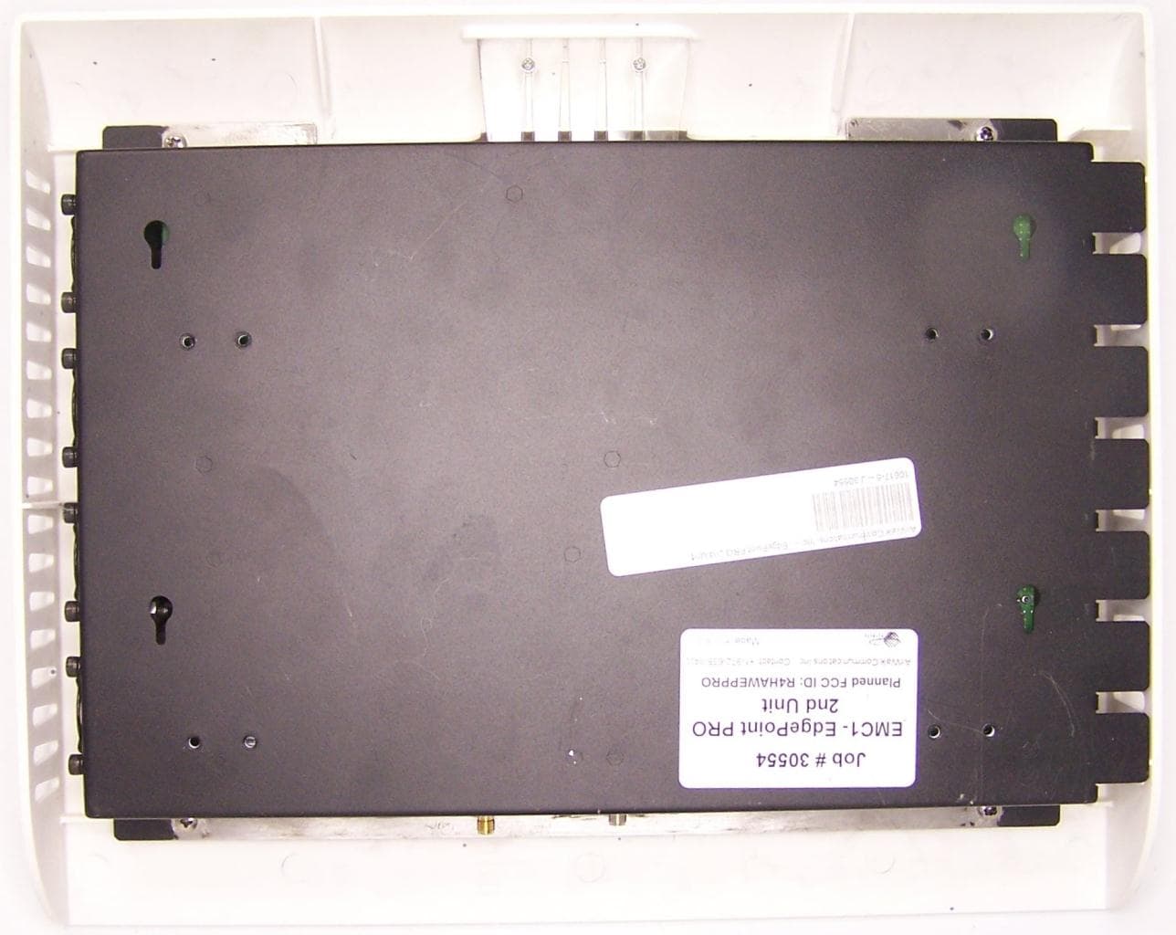
R4HAWEPPRO
Apr 25, 2011EdgePoint PRO
Equipment Class
PCB - PCS Licensed Transmitter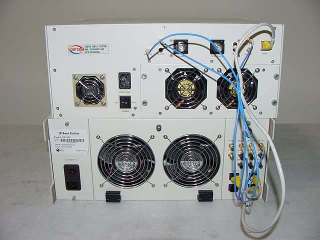
R4HAW96R19AJ1A01
Sep 21, 2004CDMA-2000 IP-Base Station
Equipment Class
PCB - PCS Licensed Transmitter