R4R-AIRTU560UMPCUMPC
Amtek System Co., Ltd.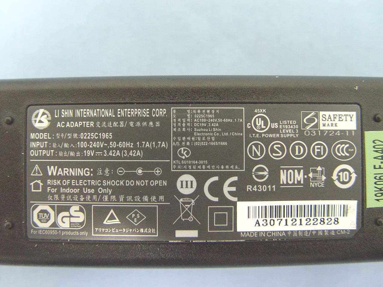
Click to zoom
Application Details
- Equipment Class
- DSS - Part 15 Spread Spectrum Transmitter
- Date of Grant
- Oct 31, 2007
- Application Purpose
- Original Equipment
- Date of Application
- Oct 31, 2007
- Equipment Note
- UMPC
- Frequency Range
- 2402.00000000 - 2480.00000000
- Company
- Amtek System Co., Ltd.
- Country
- Taiwan
Documents & Files
Document Text
Text extracted from the exhibit documents filed with the FCC. Open a document above to read the original.
Users Manual
i i Preface Copyright 2007 All Rights Reserved. The information in this document is subject to change without prior notice in order to improve reliability, design and function and does not represent a commitment on the part of the manufacturer. In no event will the manufacturer be liable for direct, indirect, special, incidental, or consequential damages arising out of the use or inability to use the product or documentation, even if advised of the possibility of such damages. This document contains proprietary information protected by copyright. All rights are reserved. No part of this manual may be reproduced by any mechanical, electronic, or other means in any form without prior written permission of the manufacturer. Safety Notices 1. Please read these safety instructions carefully. 2. All precautions and warnings on the equipment should be carefully noted. 3. Please disconnect the computer from the AC outlet before cleaning. 4. Never pour any liquids into any openings or directly onto the computer unit. This could result in fire or electrical shock. 5. Ensure the voltage range of the power outlet is between 100V and 240V before connecting the computer unit. Exceeding the maximum rated voltage may cause damage to the AC adapter or to the computer. This could result in fire or electrical shock. 6. Do not leave this equipment in a non-temperature controlled environment; storage temperatures below 4°C (39°F) or above 35°C (95°F) may damage the unit. To reduce the risk of an electric shock, which could cause personal injury, please follow all safety notices. The symbols shown are used in your documentation and on your equipment to indicate safety hazards. ii Lithium batteries can be dangerous. Danger of explosion if battery is incorrectly replaced. Replace only with the same or equivalent type recommended by the manufacturer. Dispose of used batteries according to the manufacturer’s instructions. Under no circumstances should the user attempt to disassemble the power supply. The power supply has no user-replaceable parts. Inside the power supply are hazardous voltages that can cause serious personal injury. A defective power supply must be returned to your dealer. Safety Notices for the Power Cord This equipment has a 2 or 3-wire power cord. Replace the power cord if it becomes damaged. Contact your dealer for an exact replacement. In the U.S.A. and Canada, the power cord must be a UL-listed detachable power cord (in Canada, CSA-certified). 2-wire cord SPT-2 18AWG 3-wire cord SVT or SJT, 18 AWG, 3-conductor Provided with a molded-on cord connector body at the other end. The cord length must not exceed 3 meters. Outside the U.S.A. and Canada, the plug must be rated for 250 VAC, 2.5 amp minimum, and must display an international agency approval marking. The cord must be suitable for use in the end-user’s country. Consult your dealer or the local electrical authorities if you are unsure of the type of power cord to use in your country. Voltage changes occur automatically in the power supply. Notice of EMC Compliance This equipment has been tested and found to comply with the limits for a Class B digital device, pursuant to Part 15 of the FCC Rules. These limits are designed to provide reasonable protection against harmful interference in a residential installation. iii This equipment generates, uses, and can radiate radio frequency energy and if not installed and used in accordance with the instruction manual may cause harmful interference to radio communications. However, there is no guarantee that interference will not occur in a particular installation. If this equipment does cause harmful interference to radio or television reception, which can be determined by turning the equipment off and on, the user is encouraged to try to correct the interference by one or more of the following measures: ¾ Reorient or relocate the receiving antenna. ¾ Increase the separation between the equipment and receiver. ¾ Connect the equipment into an outlet on a circuit different from that to which the receiver is connected. ¾ Consult the dealer or an experienced technician for help. Use only shielded I/O cables to connect I/O devices to this equipment. You are cautioned the changes or modifications not expressly approved by the party responsible for compliance could void your authority to use the equipment. This device complies with Part 15 of the FCC Rules. Operation is subject to the following two conditions: (1) this device will not cause harmful interference, and (2) this device must accept any interference it receive including interference that may cause undesired operation. This device and its antenna(s) must not be co-located or operating in conjunction with any other antenna or transmitter. FCC Radiation Exposure Statement This Transmitter has been demonstrated co-location compliance requirements with (Bluetooth/Model No:GUBTCR42M).This transmitter must not be co-located or operating in conjunction with any other antenna or transmitter. 1. This equipment complies with FCC RF radiation exposure limits set forth for an uncontrolled environment. To maintain compliance with FCC RF exposure compliance requirements, avoid direct contact to the transmitting antenna during transmitting. iv 2. Any changes or modifications (including the antennas) made to this device that are not expressly approved by the manufacturer may void the user’s authority to operate the equipment. Canadian EMI Compliance Statement This Class B digital apparatus meets all requirements of the Canadian Interference - Causing Equipment Regulations. European Union CE Marking Declaration This product has been tested and found to comply with the EMC requirement subject to the EU directive for CE marking. CE Declaration of Conformity For the following equipment: Ultra Mobile PC ! 0984 Is herewith confirmed to comply with the requirements set out in the Council Directive on the Approximation of the Laws of the Member States relating to El…
Text truncated - open the document above for the full version.
Cover Letter(s)
AMTEK SYSTEM CO., LTD. Address: 14F-11, No.79, Sec.1, Hsin Tai Wu Rd., Hsi Chih City, Taipei Hsien, Taiwan. Tel: 886-2-2698-0909 Fax: 886-2-2698-3939 Date: October 2, 2007 Compliance Certification Services Certification Division 561F Monterey Road Morgan Hill, CA 95037 To whom it may concern: We, the undersigned, hereby authorize the Taiwan office of Compliance Engineering Services, Inc., d.b.a. Compliance Certification Services and hereafter referred to as CCS TW, to act on our behalf in all manners relating to application for equipment authorization, including signing of all documents relating to these matters. Any and all acts carried out by CCS TW on our behalf shall have the same effect as acts of our own. We, the undersigned, hereby certify that we are not subject to a denial of federal benefits, that includes FCC benefits, pursuant to Section 5301 of the Anti-Drug Abuse Act of 1988, 21 U.S.C. 853(a). In authorizing CCS TW as our agent, we still recognize that we are responsible to: a) Comply with the relevant provisions of the certification program; b) Make all necessary arrangements for the conduct of the evaluation, including provision for examining documentation and access to all areas, records (including internal audit reports) and personnel for the purposes of evaluation (e.g. testing, inspection, assessment, surveillance, reassessment) and resolution of complaints; c) Make claims regarding certification only in respect of the scope for which certification has been granted; d) Do not use our product certification in such a manner as to bring the Certification Division into disrepute and not make any statement regarding our product certification which the Certification Division may consider misleading or unauthorized;
Cover Letter(s)
U560 WLAN & Bluetoo th Antenna Test Report Prepared By Justin Chang SLT Confidential Antenna Configuration Single antenna in Monopole Type1. Test platform: U560 2. Location: Top Camera Side 4. Cable: 0.81 (dia) x 85 mm Gray cable length + IPEX connecter Bluetooth Dual-band antenna in IFA Type1. Test platform: U560 2. Location: Upper-Front side 4. Cable: 1.13 (dia) x 80 mm Black cable length + IPEX connecter Aux Dual-band antenna in IFA Type 1. Test platform: U560 2. Location: Upper-Left side 4. Cable: 1.13 (dia) x 80 mm White cable length + IPEX connecter Main Notes Configuration Bluetooth Main Aux SLT Confidential Test Result -- VSWR Main Antenna SLT Confidential Test Result -- VSWR Aux Antenna SLT Confidential Test Result -- VSWR Bluetooth Antenna SLT Confidential Test Result – Antenna Gain H-pol V pol Total H-pol V pol Total 2400(MHz) 0.83 -0.93 1.84 -10.00 -5.93 -3.73 2450(MHz) 0.38 0.07 1.73 -10.29 -5.58 -3.49 2500(MHz) -1.25 0.04 2.23 -9.91 -6.71 -4.14 BT antenna Gain Frequenc y Max value Average WLAN Antenna -4.48 -4.58 -4.17 -3.66 -3.48 -2.77 -3.77 -3.84 -3.96 Avg dBi 2.71 2.39 2.8 1.06 1.29 2.39 -1.22 -1.24 -1.17 Peak dBi Aux -3.47 -3.64 -3.36 -2.40 -2.19 -2.36 -2.76 -2.47 -2.68 Avg dBi 1.08 2.62 2.09 1.39 1.76 1.94 -0.75 0.13 0.10 Peak dBi Main 5.875 GHz 5.725 GHz 5.47 GHz 5.35 GHz 5.15 GHz 4.90 GHz 2.50GHz 2.45 GHz 2.40 GHz HyperLAN (5.470 GHz - 5.875 GHz) (4.90 GHz - 5.350 GHz) 2G4 ISM (2.400 GHz - 2.4835 GHz) Antenna Gain SLT Confidential Test Result – Gain Pattern ISM (2.400 GHz - 2.4835 GHz) Antenna Radiation Patterns 5875(MHz) -1.23598 Average Gain -6.44 -7.16 -3.77 Average Gain -6.54 -7.17 -3.84 Average Gain -6.09 -8.07 -3.96 Average Gain -6.20 -5.37 -2.76 Average Gain -5.37 -5.60 -2.47 Average Gain -4.93 -6.62 -2.68 -1.22 -1.24 Peak Gain -3.63 -3.20 H-pol V-pol Total Peak Gain -3.11 -1.68 -1.17 Peak Gain -2.99 -2.14 -0.75 H-pol V-pol Total H-pol V-pol Total Peak Gain H-pol Total Peak Gain -1.72 -1.43 0.13 -2.49 -2.20 Peak Gain -1.98 -1.47 0.10 H-pol V-pol Total V-pol Total H-pol V-pol antenna @2.40 GHz -35-30-25-20-15-10 -5 05 E TotalH-polV-pol antenna @2.45 GHz -35-30-25-20-15-10 -5 05 E TotalH-p olV-pol antenna @2.40 GHz -35-30-25-20-15-10 -5 05 E-TotalH-p olV-pol antenna @2.45 GHz -35-30-25-20-15-10 -5 05 E TotalH-p olV-pol antenna @2.50 GHz -35-30-25-20-15-10 -5 05 E TotalH-polV-pol antenna @2.50 GHz -35-30-25-20-15-10 -5 05 E-TotalH-polV-pol 00 90 180 270 00 90 180 270 00 90 180 270 00 90 180 270 00 90 180 270 00 90 180 270 SLT Confidential Test Result – Gain Pattern UII (4.90~5.350 GHz) Antenna Radiation Patterns 5875(MHz) -1.23598 V-pol V-pol T otal -6.64 -3.48 H-pol -6.80 -6.53 -2.00 Total Average Gain Average Gain Average Gain V-pol Total H-pol H-pol -2.40 Average Gain -5.43 -5.39 H-pol V-pol Total Average Gain H-pol Average Gain -4.85 -5.60 -2.36 Peak Gain 1.28 -1.43 -5.07 -5.34 -2.19 H-pol V-pol Total V-pol Total -3.66 -5.58 -6.00 -2.77 -6.35 1.08 0.01 1.94 Peak Gain 1.31 0.10 1.29 Pe ak Gain 1.76 Pe ak Gain -0.65 1.06 1.39 Peak Gain 1.20 -0.66 2.39 Peak Gain -1.56 -0.32 antenna @4.90 GHz -35-30-25-20-15-10 -5 05 E-TotalH-polV-pol antenna @5.15 GHz -35-30-25-20-15-10 -5 05 E TotalH-polV-pol antenna @4.90 GHz -35-30-25-20-15-10 -5 05 E TotalH-polE-pol antenna @5.15 GHz -35-30-25-20-15-10 -5 05 E TotalH-polV-pol antenna @5.35 GHz -35-30-25-20-15-10 -5 05 E TotalH-polV-pol antenna @5.35 GHz -35-30-25-20-15-10 -5 05 E TotalH-polV-pol 00 90 180 270 00 90 180 270 00 90 180 270 00 90 180 270 00 90 180 270 00 90 180 270 SLT Confidential Test Result – Gain Pattern Bluetooth Antenna Radiation Patterns Average Gain -9.91 -6.71 -4.14 Average Gain -10.29 -5.58 -3.49 Average Gain -10.00 -5.93 -3.73 2.23 1.73 Peak Gain -1.25 0.04 H-pol V-pol Total Peak Gain 0.83 -0.93 1.84 Peak Gain 0.38 0.07 H-pol V-pol Total H-pol V-pol Total BT antenna @2.45 GHz -35-30-25-20-15-10 -5 05 E TotalH-polV-pol BT antenna @2.50 GHz -35-30-25-20-15-10 -5 05 E-TotalH-polV-pol BT antenna @2.40 GHz -35-30-25-20-15-10 -5 05 E-TotalH-polV-pol 00 90 180 270 00 90 180 270 00 90 180 270
External Photos
Compliance Certification Services Inc. Report No.: 70904001 Date of Issue: October 24, 2007 Page 1 Total Page: 22 Rev. 00 EXTERNAL PHOTOGRAPHS OF EUT Compliance Certification Services Inc. Report No.: 70904001 Date of Issue: October 24, 2007 Page 2 Rev.00 Compliance Certification Services Inc. Report No.: 70904001 Date of Issue: October 24, 2007 Page 3 Rev. 00 Compliance Certification Services Inc. Report No.: 70904001 Date of Issue: October 24, 2007 Page 4 Rev.00 Compliance Certification Services Inc. Report No.: 70904001 Date of Issue: October 24, 2007 Page 5 Rev.00 Compliance Certification Services Inc. Report No.: 70904001 Date of Issue: October 24, 2007 Page 6 Rev.00
Internal Photos
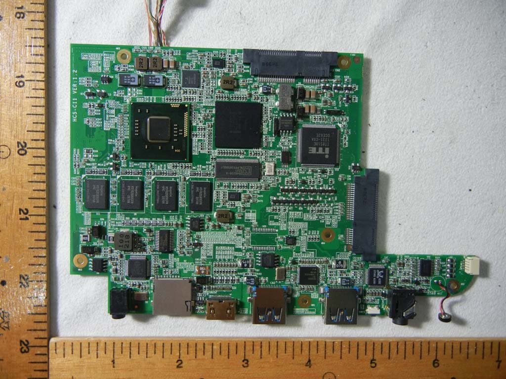
Compliance Certification Services Inc. Report No.: 70904001 Date of Issue: October 24, 2007 Page 7 Rev.00 INTERNAL PHOTOGRAPHS OF EUT Compliance Certification Services Inc. Report No.: 70904001 Date of Issue: October 24, 2007 Page 8 Rev.00 Compliance Certification Services Inc. Report No.: 70904001 Date of Issue: October 24, 2007 Page 9 Rev.00 WLAN Antenna Compliance Certification Services Inc. Report No.: 70904001 Date of Issue: October 24, 2007 Page 10 Rev.00 WLAN Location Compliance Certification Services Inc. Report No.: 70904001 Date of Issue: October 24, 2007 Page 11 Rev.00 Compliance Certification Services Inc. Report No.: 70904001 Date of Issue: October 24, 2007 Page 12 Rev.00 Compliance Certification Services Inc. Report No.: 70904001 Date of Issue: October 24, 2007 Page 13 Rev.00 Bluetooth Antenna Bluetooth Location Compliance Certification Services Inc. Report No.: 70904001 Date of Issue: October 24, 2007 Page 14 Rev.00
Internal Photos
Compliance Certification Services Inc. Report No.: 70904001 Date of Issue: October 24, 2007 Page 15 Rev.00 Battery Compliance Certification Services Inc. Report No.: 70904001 Date of Issue: October 24, 2007 Page 16 Rev.00 WLAN Module Compliance Certification Services Inc. Report No.: 70904001 Date of Issue: October 24, 2007 Page 17 Rev.00 Compliance Certification Services Inc. Report No.: 70904001 Date of Issue: October 24, 2007 Page 18 Rev.00 Compliance Certification Services Inc. Report No.: 70904001 Date of Issue: October 24, 2007 Page 19 Rev.00 Bluetooth Module Compliance Certification Services Inc. Report No.: 70904001 Date of Issue: October 24, 2007 Page 20 Rev.00 WLAN Antenna Compliance Certification Services Inc. Report No.: 70904001 Date of Issue: October 24, 2007 Page 21 Rev.00 Compliance Certification Services Inc. Report No.: 70904001 Date of Issue: October 24, 2007 Page 22 Rev.00 Bluetooth Antenna
Parts List/Tune Up Info
AMTEK SYSTEM CO., LTD. 14F-11, No.79, Sec.1, Hsin Tai Wu rd., Hsi Chih City, Taipei Hsien, Taiwan Tel: 02-2698-0909 / FAX: 02-2698-3939 Bluetooth Declaration Per FCC 15.247 Requirements 1 Output power and channel separation of a Bluetooth device in the different operating modes: The different operating modes (data-mode, acquisition-mode) of a Bluetooth device don’t influence the output power and the channel spacing. There is only one transmitter which is driven by identical input parameters concerning these two parameters. Only a different hopping sequence will be used. For this reason the check of these RF parameters in one op-mode is sufficient. 2 Frequency range of a Bluetooth device: Hereby we declare that the maximum frequency of this device is: 2402 – 2480 MHz. This is according the Bluetooth Core Specification V 1.0B (+ critical errata) for devices which will be operated in the USA. This was checked during the Bluetooth Qualification tests (Test Case: TRM/CA/04-E). Other frequency ranges ( e.g. for Spain, France, Japan) which are allowed according the Core Specification are not supported by this device. 3 Co-ordination of the hopping sequence in data mode to avoid simultaneous occupancy by multiple transmitters: Bluetooth units which want to communicate with other units must be organized in a structure called piconet. This piconet consist of max. 8 Bluetooth units. One unit is the master the other seven are the slaves. The master co-ordinates frequency occupation in this piconet for all units. As the master hop sequence is derived from it’s BD address which is unique for every Bluetooth device, additional masters intending to establish new piconets will always use different hop sequences. 4 Example of a hopping sequence in data mode: Example of a 79 hopping sequence in data mode: 40, 21, 44, 23, 42, 53, 46, 55, 48, 33, 52, 35, 50, 65, 54, 67, 56, 37, 60, 39, 58, 69, 62, 71, 64, 25, 68, 27, 66, 57, 70, 59, 72, 29, 76, 31, 74, 61, 78, 63, 01, 41, 05, 43, 03, 73, 07, 75, 09, 45, 13, 47, 11, 77, 15, 00, 64, 49, 66, 53, 68, 02, 70, 06, 01, 51, 03, 55, 05, 04 5 Equally average use of frequencies in data mode and behaviour for short transmissions: The generation of the hopping sequence in connection mode depends essentially on two input values: 1. LAP/UAP of the master of the connection 2. Internal master clock The LAP (lower address part) are the 24 LSB’s of the 48 BD_ADDRESS. The BD_ADDRESS is an unambiguous number of every Bluetooth unit. The UAP (upper address part) are the 24 MSB’s of the 48 BD_ADDRESS. The internal clock of a Bluetooth unit is derived from a free running clock which is never adjusted and is never turned off. For synchronisation with other units only offset are used. It has no relation to the time of the day. Its resolution is at least half the RX/TX slot length of 312.5 μs. The clock has a cycle of about one day (23h30). In most case it is implemented as 28 bit counter. For the deriving of the hopping AMTEK SYSTEM CO., LTD. 14F-11, No.79, Sec.1, Hsin Tai Wu rd., Hsi Chih City, Taipei Hsien, Taiwan Tel: 02-2698-0909 / FAX: 02-2698-3939 sequence the entire LAP (24 bits), 4 LSB’s (4 bits) (Input 1) and the 27 MSB’s of the clock (Input 2) are used. With this input values different mathematical procedures (permutations, additions, XOR-operations) are performed to generate the sequence. This will be done at the beginning of every new transmission. Regarding short transmissions the Bluetooth system has the following behaviors: The first connection between the two devices is established, a hopping sequence was generated. For transmitting the wanted data the complete hopping sequence was not used. The connection ended. The second connection will be established. A new hopping sequence is generated. Due to the fact that the Bluetooth clock has a different value, because the period between the two transmission is longer (and it cannot be shorter) than the minimum resolution of the clock (312.5 μs). The hopping sequence will always differ from the first one. 6 Receiver input bandwidth and behaviors for repeated single or multiple packets: The input bandwidth of the receiver is 1 MHz. In every connection one Bluetooth device is the master and the other one is the slave. The master determines the hopping sequence (see chapter 5). The slave follows this sequence. Both devices shift between RX and TX time slot according to the clock of the master. Additionally the type of connection (e.g. single or multislot packet) is set up at the beginning of the connection. The master adapts its hopping frequency and its TX/RX timing according to the packet type of the connection. Also the slave of the connection will use these settings. Repeating of a packet has no influence on the hopping sequence. The hopping sequence generated by the master of the connection will be followed in any case. That means, a repeated packet will not be send on the same frequency, it is send on the next frequency of the hopping sequence. 7 Dwell time in data mode The dwell time of 0.3797s within a 30 second period in data mode is independent from the packet type (packet length). The calculation for a 30 second period is a follows: Dwell time = time slot length * hop rate / number of hopping channels *30s Example for a DH1 packet (with a maximum length of one time slot) Dwell time = 625 μs * 1600 1/s / 79 * 30s = 0.3797s (in a 30s period) For multislot packet the hopping is reduced according to the length of the packet. Example for a DH5 packet (with a maximum length of five time slots) Dwell time = 5 * 625 μs * 1600 * 1/5 *1/s / 79 * 30s = 0.3797s (in a 30s period) This is according the Bluetooth Core Specification V 1.0B (+ critical errata) for all Bluetooth devices. There for all Bluetooth devices comply with the FCC dwell time requirement in data mode. This was checked during the Bluetooth Qualification tests. The Dwell time in hybrid mode is measured and stated in the test report. 8 Channel Separation in hybrid…
Text truncated - open the document above for the full version.
RF Exposure Info
Compliance Certification Services Inc. Report No.: 70914001-SF FCC ID: R4R-AIRTU560UMPC Date of Issue: October 9, 2007 Note: This report shall not be reproduced except in full, without the written approval of Compliance Certification Services Inc. This document may be altered or revised by Compliance Certification Services Inc. personnel only, and shall be noted in the revision section of the document. Page 1 Total Page: 30 Rev. 00 ANSI/IEEE Std. C95.1-1992 in accordance with the requirements of FCC Report and Order: ET Docket 93-62, and OET Bulletin 65 Supplement C FCC TEST REPORT For UMPC Trade Name: AMtek System Co.,Ltd. Model: U560 Issued to AMTEK SYSTEM CO., LTD. 14F-11, No.79, Sec.1, Hsin Tai Wu rd., Hsi Chih City, Taipei Hsien, Taiwan Issued by Compliance Certification Services Inc. No. 11, Wugong 6th Rd., Wugu Industrial Park, Taipei Hsien 248, Taiwan. http://www.ccsemc.com.tw [email protected] Compliance Certification Services Inc. Report No: 70914001-SF Date of Issue: October 9, 2007 Page 2 Rev. 00 TABLE OF CONTENTS 1. CERTIFICATE OF COMPLIANCE (SAR EVALUATION) ......................................................3 2. EUT DESCRIPTION ....................................................................................................................4 3. REQUIREMENTS FOR COMPLIANCE TESTING DEFINED BY THE FCC .........................5 4. DOSIMETRIC ASSESSMENT SYSTEM ...................................................................................5 4.1 MEASUREMENT SYSTEM DIAGRAM .........................................................................6 4.2 SYSTEM COMPONENTS.................................................................................................7 5. EVALUATION PROCEDURES ..................................................................................................9 6. MEASUREMENT UNCERTAINTY .........................................................................................13 7. EXPOSURE LIMIT ....................................................................................................................14 8. TYPICAL COMPOSITION OF INGREDIENTS FOR LIQUID TISSUE PHANTOMS .........15 9. MEASUREMENT RESULTS ....................................................................................................16 9.1 SYSTEM PERFORMANCE CHECK..............................................................................16 9.2 TEST LIQUID CONFIRMATION...................................................................................17 9.3 EUT TUNE-UP PROCEDURES AND TEST MODE.....................................................18 9.4 SAR MEASUREMENTS RESULTS...............................................................................21 10. EUT PHOTOS............................................................................................................................27 11. EQUIPMENT LIST & CALIBRATION STATUS....................................................................28 12. FACILITIES ...............................................................................................................................29 13. REFERENCES............................................................................................................................29 14. ATTACHMENTS .......................................................................................................................30 Compliance Certification Services Inc. Report No: 70914001-SF Date of Issue: October 9, 2007 Page 3 Rev. 00 1. CERTIFICATE OF COMPLIANCE (SAR EVALUATION) Applicant: AMTEK SYSTEM CO., LTD. 14F-11, No.79, Sec.1, Hsin Tai Wu rd., Hsi Chih City, Taipei Hsien, Taiwan Equipment Under Test: UMPC Trade Name: AMtek System Co.,Ltd. Model Number: U560 Date of Test: October 4, 2007 Device Category: PORTABLE DEVICES Exposure Category: GENERAL POPULATION/UNCONTROLLED EXPOSURE APPLICABLE STANDARDS STANDARD TEST RESULT FCC OET 65 Supplement C No non-compliance noted Deviation from Applicable Standard None The device was tested by Compliance Certification Services Inc. in accordance with the measurement methods and procedures specified in OET Bulletin 65 Supplement C (Edition 01-01). The test results in this report apply only to the tested sample of the stated device/equipment. Other similar device/equipment will not necessarily produce the same results due to production tolerance and measurement uncertainties. Approved by: Rex Lai Section Manager Compliance Certification Services Inc. Compliance Certification Services Inc. Report No: 70914001-SF Date of Issue: October 9, 2007 Page 4 Rev. 00 2. EUT DESCRIPTION Product UMPC Trade Name AMtek System Co.,Ltd. Model Number U560 Model Discrepancy N/A Frequency Range 802.11b: 2400 ~ 2483.5 MHz 802.11g: 2400 ~ 2483.5 MHz Bluetooth: 2400 ~ 2483.5 MHz Max. O/P Power: (Conducted/Peak) 802.11b: 13.91 dBm 802.11g: 21.02 dBm Bluetooth: 3.12 dBm Max. SAR (1g): 802.11b: 0.133 W/kg 802.11g: 0.617 W/kg Modulation Technique 802.11b: Direct Sequence Spread Spectrum (DSSS) 802.11g: Orthogonal Frequency Division Multiplexing (OFDM) Bluetooth: FHSS (GFSK) Antenna Specification Antenna type: WLAN antenna: PIFA antenna Bluetooth antenna: PIFA antenna Remark: The sample selected for test was prototype that approximated to production product and was provided by manufacturer. Compliance Certification Services Inc. Report No: 70914001-SF Date of Issue: October 9, 2007 Page 5 Rev. 00 3. REQUIREMENTS FOR COMPLIANCE TESTING DEFINED BY THE FCC The US Federal Communications Commission has released the report and order “Guidelines for Evaluating the Environmental Effects of RF Radiation", ET Docket No. 93-62 in August 1996 [1]. The order requires routine SAR evaluation prior to equipment authorization of portable transmitter devices, including portable telephones. For consumer products, the applicable limit is 1.6 mW/g for an uncontrolled environment and 8.0 mW/g for an occupational/controlled environment as recommended by the ANSI/IEEE standard C95.1-19…
Text truncated - open the document above for the full version.
RF Exposure Info
Date/Time:10/4/2007 9:09:22 AM Test Laboratory: Compliance Certification Services Inc. D2450V2 SN-728 Body DUT: Dipole 2450 MHz; Type: D2450V2; Serial: D2450V2 - SN:728 Communication System: CW2450; Frequency: 2450 MHz;Duty Cycle: 1:1 Medium parameters used: f = 2450 MHz; ı = 1.97 mho/m; İ r = 51.8; ȡ = 1000 kg/m 3 Phantom section: Flat Section Air Temperature:25.4 deg C;Liquid Temperature:24.4 deg C Area Scan Find Secondary Maximum Within 2dB and with a peak SAR value greater than 0.0012W/kg DASY4 Configuration: z Probe: EX3DV3 - SN3531; ConvF(7.88,7.88,7.88); z Sensor-Surface: 2.5mm (Mechanical Surface Detection) z Electronics: DAE4 Sn558; Calibrated: 8/29/2007 z Phantom: SAM 12; Type: SAM V4.0; Serial: TP-1150 z Measurement SW: DASY4, V4.7 Build 53; Postprocessing SW: SEMCAD, V1.8 Build 172 Pin=250mW,d=10mm/Area Scan (6x6x1): Measurement grid: dx=15mm, dy=15mm Maximum value of SAR (measured) = 14.2 mW/g Pin=250mW,d=10mm/Zoom Scan (5x5x7)/Cube 0: Measurement grid: dx=7.5mm, dy=7.5mm, dz=5mm Reference Value = 96.6 V/m; Power Drift = -0.028 dB Peak SAR (extrapolated) = 28.3 W/kg SAR(1 g) = 13.5 mW/g; SAR(10 g) = 6.18 mW/g Maximum value of SAR (measured) = 19.2 mW/g Page1 Page2 Date/Time:10/4/20079:37:09AM Test Laboratory: Compliance Certification Services Inc. 802.11b Tip edge Touched close mode Main antenna DUT: U560; Type: Ultra Mobile PC; Serial: N/A Communication System: IEEE 802.11b WLAN; Frequency: 2437 MHz;Duty Cycle: 1:1 Medium parameters used (interpolated): f = 2437 MHz; ı = 1.95 mho/m; İ r = 51.8; ȡ = 1000 kg/m 3 Phantom section: Flat Section Air Temperature:25.4 deg C;Liquid Temperature:24.4 deg C Area Scan Find Secondary Maximum Within 2dB and with a peak SAR value greater than 0.0012W/kg DASY4 Configuration: z Probe: EX3DV3 - SN3531; ConvF(7.88, 7.88, 7.88); z Sensor-Surface: 2.5mm (Mechanical Surface Detection) z Electronics: DAE4 Sn558; Calibrated: 8/29/2007 z Phantom: SAM 12; Type: SAM V4.0; Serial: TP-1150 z Measurement SW: DASY4, V4.7Build53; Postprocessing SW: SEMCAD, V1.8 Build 172 Middle CH Rate=1M bit/Area Scan (6x15x1): Measurement grid: dx=15mm, dy=15mm Maximum value of SAR (measured) = 0.097 mW/g Middle CH Rate=1M bit/Zoom Scan (5x5x7)/Cube 0: Measurement grid: dx=7.5mm, dy=7.5mm, dz=5mm Reference Value = 5.11 V/m; Power Drift = -0.093 dB Peak SAR (extrapolated) = 0.189 W/kg SAR(1 g) = 0.102 mW/g; SAR(10 g) = 0.044 mW/g Maximum value of SAR (measured) = 0.181 mW/g Page1 Page2 Date/Time:10/4/20079:58:18AM Test Laboratory: Compliance Certification Services Inc. 802.11b Tip edge Touched close mode Aux antenna DUT: U560; Type: Ultra Mobile PC; Serial: N/A Communication System: IEEE 802.11b WLAN; Frequency: 2437 MHz;Duty Cycle: 1:1 Medium parameters used (interpolated): f = 2437 MHz; ı = 1.95 mho/m; İ r = 51.8; ȡ = 1000 kg/m 3 Phantom section: Flat Section Air Temperature:25.4 deg C;Liquid Temperature:24.4 deg C Area Scan Find Secondary Maximum Within 2dB and with a peak SAR value greater than 0.0012W/kg DASY4 Configuration: z Probe: EX3DV3 - SN3531; ConvF(7.88, 7.88, 7.88); z Sensor-Surface: 2.5mm (Mechanical Surface Detection) z Electronics: DAE4 Sn558; Calibrated: 8/29/2007 z Phantom: SAM 12; Type: SAM V4.0; Serial: TP-1150 z Measurement SW: DASY4, V4.7 Build 53; Postprocessing SW: SEMCAD, V1.8 Build 172 Middle CH Rate=1M bit/Area Scan (6x15x1): Measurement grid: dx=15mm, dy=15mm Maximum value of SAR (measured) = 0.013 mW/g Middle CH Rate=1M bit/Zoom Scan (5x5x7)/Cube 0: Measurement grid: dx=7.5mm, dy=7.5mm, dz=5mm Reference Value = 1.81 V/m; Power Drift = -0.082 dB Peak SAR (extrapolated) = 0.025 W/kg SAR(1 g) = 0.013 mW/g; SAR(10 g) = 0.00689 mW/g Maximum va…
Text truncated - open the document above for the full version.
Contact Information
Applicant
Dick Lien(Safety Manager)
Technical Contact
Compliance Certification Services Inc.Jessica Ho
[email protected]886-2-22999720
No. 81-1, Lane 210, Bade Rd. 2, Luchu Hsiang, · Taoyuan Hsien · Taiwan
Non-Technical Contact
Compliance Certification Services Inc.Jessica Ho
[email protected]886-2-22999720
Test Firm
Compliance Certification Services Inc.Kurt Chen
Technical Specifications
| # | Rule Parts | Frequency Range | Power Output |
|---|---|---|---|
| 1 | 15C | 2.40 GHz - 2.48 GHz | 2.05 mW |
Other Applications from Amtek System Co., Ltd.
R4RTN26JAEYOUNG
Apr 30, 2013Tablet PC
Equipment Class
DTS - Digital Transmission System
R4RT10GX210ARM
Dec 05, 2012Gaming Tablet
Equipment Class
DTS - Digital Transmission System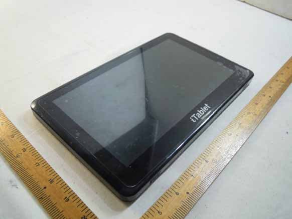
R4RAIRW101M072
Jan 10, 2011Tablet PC
Equipment Class
DSS - Part 15 Spread Spectrum Transmitter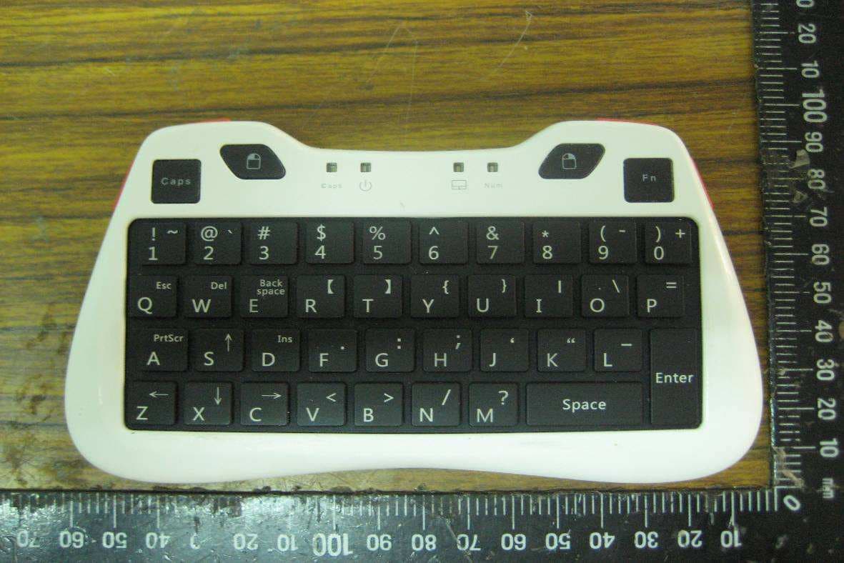
R4RBK01
Oct 13, 2010Fairy Keyboard
Equipment Class
DSS - Part 15 Spread Spectrum Transmitter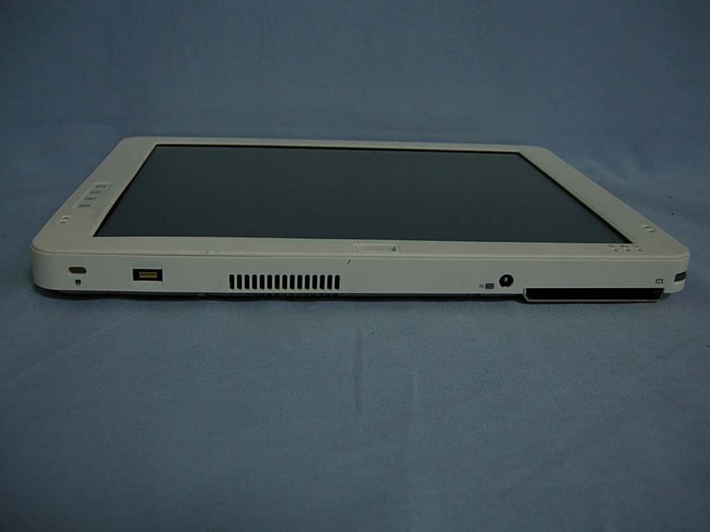
R4RAIRT22XQXKN2
Jan 01, 2008Tablet PC
Equipment Class
DTS - Digital Transmission System