R4RITABLETRFM01RF Mouse
Amtek System Co., Ltd.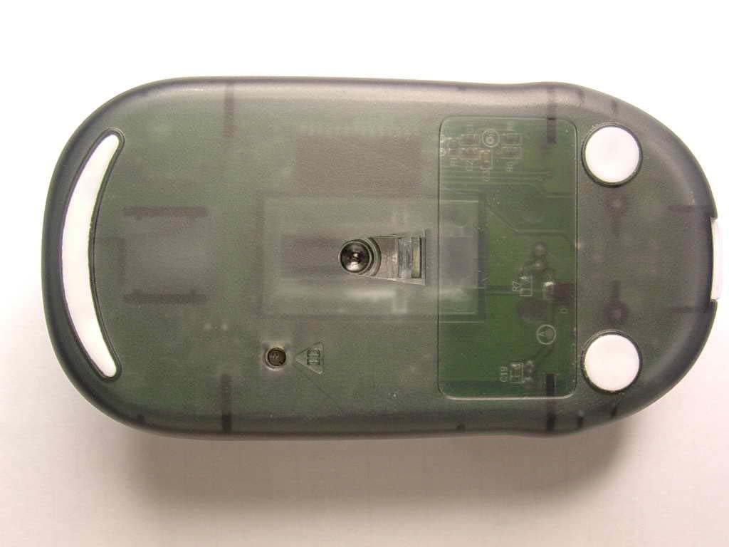
Click to zoom
Application Details
- Equipment Class
- DXX - Part 15 Low Power Communication Device Transmitter
- Date of Grant
- Jul 21, 2004
- Application Purpose
- Original Equipment
- Date of Application
- Jul 21, 2004
- Equipment Note
- RF Mouse
- Frequency Range
- 27.04500000 - 27.04500000
- Company
- Amtek System Co., Ltd.
- Country
- Taiwan
Documents & Files
Document Text
Text extracted from the exhibit documents filed with the FCC. Open a document above to read the original.
Users Manual
1 Wireless Keyboard & Mouse Using Instruction 2 Getting Started Guide 1. Install the battery: (1) Remove the battery cover on the top. (2) Insert the Alkaline Batteries enclosed in the package into the battery compartment, and follow the directive marks to insert batteries. (3) Replace the cover carefully. Note: Once the batteries are placed correctly, the mouse optical LED located at the bottom will be lit up. If the LED isn’t lit up, please remove the batteries.Recheck the battery direction and install anew. 2. Connect the receiver: Please connect the receiver to the USB port on the computer. Windows 98 or higher o 3. Establish communication connection After plug the receiver to your computer, the LED on the receiver will be lit up. To press the ID button on the receiver in first then press the button on the bottom of both mouse and keyboard .If the receiver connects with the mouse successfully, LED indicator on the receiver will blink quickly and stop blinking. Same as Keyboard ID setting. 4. Important Note ° To optimize the performance of your RF reception, please make your receiver away from electrical devices. Avoid using your RF optical mouse on a metal surface. That may 3 slow down the response of the mouse or cause the response failure of the mouse . ° Do not mix different brand batteries or mix old and new batteries in the mouse. ° In order to extend the life of the batteries ,using your mouse on white or bright surfaces are recommended. ° If you will not use the mouse & keyboard for a long time, please take the batteries apart off from Mouse and turn the power switch off on the bottom of keyboard to extend its using life. ° There are 2 LEDs on the receiver, One is Color in red and will be turn on when you connected to system and will blinking when you set ID , moving mouse or press any key on keyboard. The other is color in Green. This LED will be turned on when you press Caps Lock key. There is one LED on Keyboard ,It’s color in red and only be turned on when the battery Low. Please remove the battery cover and change new Batteries. 5. Trouble shooting The mouse does not work or is not detected. ° Check the USB make sure receiver is connected correctly. ° When the battery power is low, please change new batteries by same brand or same specification. Alkaline Batteries are recommended ° Reset the ID button of mouse/Keyboard and receiver.follow the “Establish communication 4 connection ” stepor Unplugged the receiver and re-connect to your PC again ° With power saving design, if you don’t use mouse about 8 minutes, it will enter a suspend mode to sleep automatically. Please press right or left button of mouse to wake up the mouse. ° For desktop PC, using the USB extension cable to let the receiver closer your mouse can have better transmitting performance. Packing contents RF Wireless Optical Mouse RF Wireless Slim Keyboard Receiver AA size Alkaline Batteries x 4 Using instruction Federal Communications Commission (FCC) Statement This equipment has been tested and found to comply with the limits for a Class B Digital Device, pursuant to Part 15 of the FCC Rules. These limits are designed to provide reasonable protection against harmful interference in a residential installation. This equipment generates, uses and can radiate radio frequency energy and, if not installed and used in accordance with the instruction, may cause harmful interference to radio communication. However, there is no guarantee that interference will not occur in a particular installation. If this equipment does cause harmful interference to radio or television reception, which can be determined by turning the equipment off and on, the user is encouraged to try to correct the interference by one or more of the following measures. 5 -Reorient or relocate the receiving antenna. -Increase the separation between the equipment and receiver. -Connect the equipment into an outlet on a circuit different from that to which the receiver is connected. -Consult the dealer or an experienced radio/TV technician for help. You are cautioned that changes or modifications not expressly approved by the party responsible for complies could void your authority to operate the equipment. This device complies with Part 15 of the FCC Rules. Operation is subject to the following two conditions: (1) This device may not cause harmful interference. (2) This device must accept any interference received, including interference that may cause undesired operation. IMPORTANT NOTE Any changes or modifications (including the antennas) made to this device that are not expressly approved by the manufacturer may void the user’s authority to operate the equipment. European Union CE Marking Declaration This product has been tested and found to comply with the EMC requirement subject to the EU directive for CE marking.
External Photos
Compliance Certification Services Inc. Report No: 40617204 Date of Issue: June 17, 2004 Page 1 EXTERNAL PHOTOGRPHS OF EUT
Internal Photos
Compliance Certification Services Inc. Report No: 40617204 Date of Issue: June 17, 2004 Page 2 INTERNAL PHOTOGRPHS OF EUT Compliance Certification Services Inc. Report No: 40617204 Date of Issue: June 17, 2004 Page 3
Operational Description
RF Mouse TX Model: Air-M01 RF Mouse transmitter function block 1. Power amplifier is to support enough current to drive the antenna. 2. C4、C7、C9 for antenna matching circuit. Key Switches X.Y.Z. Encoder Antenna Mouse Transmitter IC (DC/DC embedded) Battery RF Crystal 27.045MHz Clock Crystal 76.8KHz RF
Test Report
Compliance Certification Services Inc. Report No: 40617204-RP FCC ID: R4RITABLETRFM01 Date of Issue: May 11, 2004 Note: This report shall not be reproduced except in full, without the written approval of Compliance Certification Services Inc. This document may be altered or revised by Compliance Certification Services Inc. personnel only, and shall be noted in the revision section of the document. Page 1 of 16 FCC 47 CFR PART 15 SUBPART C TEST REPORT For Amtek System Co., Ltd. RF Mouse Model: Air-M01 Trade Name: iTablet Prepared for Amtek System Co., Ltd. 14F-11, No. 79, Sec. 1, Hsin Tai Wu Rd., His Chih City, Taipei 221, Taiwan, R.O.C. Prepared by Compliance Certification Services Inc. No. 81-1, Lane 210, Bade Rd. 2, Luchu Hsiang, Taoyuan Hsien, (338) Taiwan, R.O.C. TEL: 886-3-324-0332 FAX: 886-3-324-5235 Compliance Certification Services Inc. Report No: 40617204-RP FCC ID: R4RITABLETRFM01 Date of Issue: May 11, 2004 Page 2 TABLE OF CONTENTS 1. TEST RESULT CERTIFICATION............................................................................................. 3 2. EUT DESCRIPTION .................................................................................................................... 4 3. TEST METHODOLOGY ............................................................................................................. 5 3.1 EUT CONFIGURATION.............................................................................................................. 5 3.2 EUT EXERCISE......................................................................................................................... 5 3.3 GENERAL TEST PROCEDURES.................................................................................................. 5 3.4 FCC PART 15.205 RESTRICTED BANDS OF OPERATIONS ............................................. 6 3.5 DESCRIPTION OF TEST MODES................................................................................................. 6 4. INSTRUMENT CALIBRATION................................................................................................. 7 5. FACILITIES AND ACCREDITATIONS ................................................................................... 8 5.1 FACILITIES.............................................................................................................................. 8 5.2 EQUIPMENT............................................................................................................................. 8 5.3 LABORATORY ACCREDITATIONS AND LISTING....................................................................... 8 5.4 TABLE OF ACCREDITATIONS AND LISTINGS............................................................................ 9 6. SETUP OF EQUIPMENT UNDER TEST ................................................................................ 10 6.1 SETUP CONFIGURATION OF EUT............................................................................................ 10 6.2 SUPPORT EQUIPMENT .................................................................................................... 10 7. FCC PART 15.227 REQUIREMENTS...................................................................................... 11 7.1 RADIATED EMISSIONS........................................................................................................... 11 7.2 POWERLINE CONDUCTED EMISSIONS.................................................................................... 15 Compliance Certification Services Inc. Report No: 40617204-RP FCC ID: R4RITABLETRFM01 Date of Issue: May 11, 2004 Page 4 2. EUT DESCRIPTION Product RF Mouse Trade Name iTablet Model Number Air-M01 Model Difference N/A Power Supply Powered by AAA batteries × 2 (Rating: 2 × 1.5Vdc) Frequency Range 27.045 MHz Modulation Technique FSK Note: This submittal(s) (test report) is intended for FCC ID: R4RITABLETRFM01 filing to comply with Section 15.227 of the FCC Part 15, Subpart C Rules. Compliance Certification Services Inc. Report No: 40617204-RP FCC ID: R4RITABLETRFM01 Date of Issue: May 11, 2004 Page 5 3. TEST METHODOLOGY The tests documented in this report were performed in accordance with ANSI C63.4 and FCC CFR 47 2.1046, 2.1047, 2.1049, 2.1051, 2.1053, 2.1055, 2.1057, and 15.227. 3.1 EUT CONFIGURATION The EUT configuration for testing is installed on RF field strength measurement to meet the Commissions requirement and operating in a manner that intends to maximize its emission characteristics in a continuous normal application. 3.2 EUT EXERCISE The EUT was operated in the engineering mode to fix the TX frequency that was for the purpose of the measurements. 3.3 GENERAL TEST PROCEDURES Conducted Emissions The EUT is placed on the turntable, which is 0.8 m above ground plane. According to the requirements in Section 13.1.4.1 of ANSI C63.4.Conducted emissions from the EUT measured in the frequency range between 0.15 MHz and 30MHz using CISPR Quasi-peak and average detector modes. Radiated Emissions The EUT is placed on a turn table, which is 0.8 m above ground plane. The turntable shall rotate 360 degrees to determine the position of maximum emission level. EUT is set 3m away from the receiving antenna, which varied from 1m to 4m to find out the highest emission. And also, each emission was to be maximized by changing the polarization of receiving antenna both horizontal and vertical. In order to find out the max. emission, the relative positions of this hand-held transmitter (EUT) was rotated through three orthogonal axes according to the requirements in Section 13.1.4.1 of ANSI C63.4. Compliance Certification Services Inc. Report No: 40617204-RP FCC ID: R4RITABLETRFM01 Date of Issue: May 11, 2004 Page 6 3.4 FCC PART 15.205 RESTRICTED BANDS OF OPERATIONS (a) Except as shown in paragraph (d) of this section, only spurious emissions are permitted in any of the frequency bands listed below: MHz MHz MHz GHz 0.090 - 0.110 1 0.495 - 0.505 2.1735 - 2.1905 4.125 - 4.128 4.17725 …
Text truncated - open the document above for the full version.
Test Setup Photos
Compliance Certification Services Inc. Report No: 40617204-RP FCC ID: R4RiTabletRFM01 Date of Issue: May 11, 2004 Page 17 APPENDIX 1 PHOTOGRPHS OF TEST SETUP Radiated Emission Set up Photos
Contact Information
Applicant
Dick Lien(Safety Manager)
Test Firm
Compliance Certification Services Inc.Tony Houng
Technical Specifications
| # | Rule Parts | Frequency Range | Power Output |
|---|---|---|---|
| 1 | 15C | 27.045 MHz - 27.045 MHz | - |
Other Applications from Amtek System Co., Ltd.
R4RTN26JAEYOUNG
Apr 30, 2013Tablet PC
Equipment Class
DTS - Digital Transmission System
R4RT10GX210ARM
Dec 05, 2012Gaming Tablet
Equipment Class
DTS - Digital Transmission System
R4RAIRW101M072
Jan 10, 2011Tablet PC
Equipment Class
DSS - Part 15 Spread Spectrum Transmitter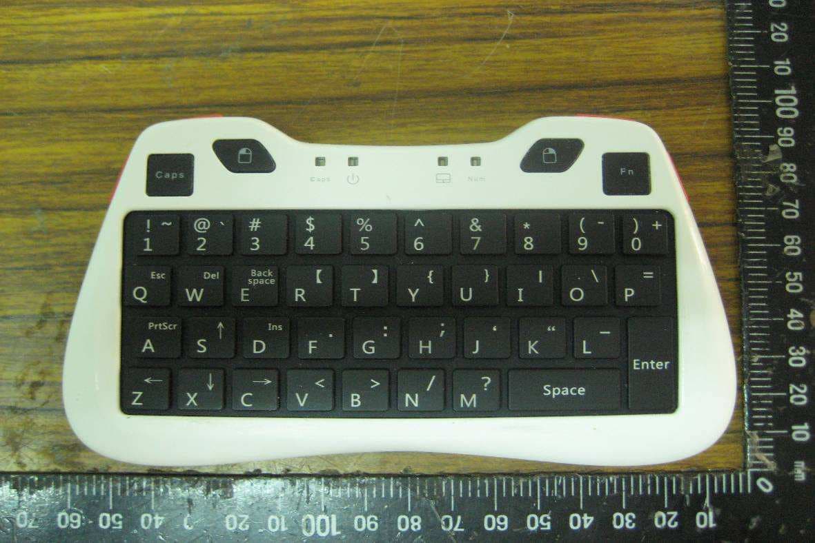
R4RBK01
Oct 13, 2010Fairy Keyboard
Equipment Class
DSS - Part 15 Spread Spectrum Transmitter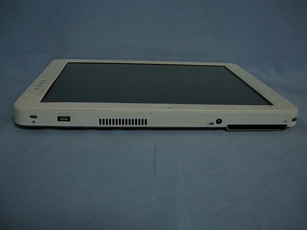
R4RAIRT22XQXKN2
Jan 01, 2008Tablet PC
Equipment Class
DTS - Digital Transmission System