R5WNGTT1400PCS MOBILE PHONE
NewGen Telecom. Co., Ltd.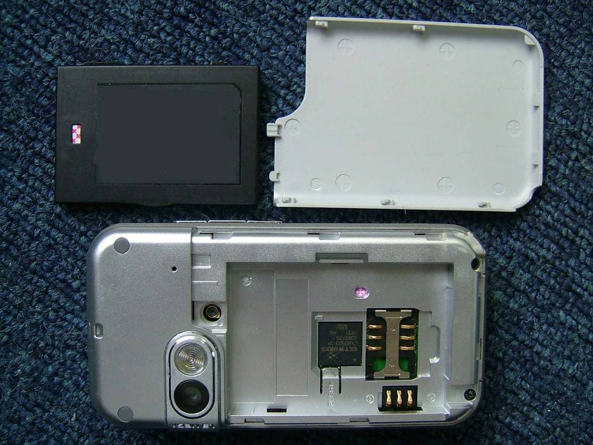
Click to zoom
Application Details
- Equipment Class
- PCE - PCS Licensed Transmitter held to ear
- Date of Grant
- Feb 19, 2006
- Application Purpose
- Original Equipment
- Date of Application
- Feb 19, 2006
- Equipment Note
- PCS MOBILE PHONE
- Frequency Range
- 1850.20000000 - 1909.80000000
- Company
- NewGen Telecom. Co., Ltd.
- Country
- South Korea
Documents & Files
Document Text
Text extracted from the exhibit documents filed with the FCC. Open a document above to read the original.
Users Manual
1 Welcome!! Thank you for choosingT1400 mobile phone! Please read this manual carefully before you use your mobile phone. For efficient use of your mobile phone, we recommend you to read the Safety and General Information chapter in advance. * Please read before using the mobile phone 3 CONTENTS 2 CONTENTS Safety and General Information6 Package contents8 About Your Phone9 Phone overview 9 Key definition 10 Display of screen12 Status icon 14 Installing and Removing SIM card16 Installing SIM card 16 Removing SIM card 16 Installing and Removing battery 17 Installing the battery 17 Removing the battery 17 Charging the battery 19 Basic Function20 Power on / off 20 About PIN/PUK 21 Making a call 23 Answering a call 23 Missed a call 23 In call menu 24 Main Menu30 Overview of main menu 30 Setting 31 Sound 30 Phone 33 Phone mode34 Display36 Security set38 Network42 Net Account45 Message49 SMS49 MMS 56 My favorites 64 MP3 64 Videos 67 Sounds 70 Pictures 72 Images 73 Avatar76 Others76 USB connection78 Storage79 WAP80 Recent page80 Homepage80 Go to URL81 Bookmark81 Push message82 5 CONTENTS 4 CONTENTS Multimedia 83 MP3 player 83 Movie player 85 Camera shot90 Fun95 Java 95 Game 95 Avatar97 Phone book98 List98 Call history 102 Accessories104 Dictionary 104 Calculator106 Clock alarm106 Schedule107 Currency 110 World time 111 Stopwatch 111 STK112 Reference Information113 Battery113 Battery time 113 Caution 114 Entering Text115 Input method116 Data Format122 Troubleshooting123 Technical information125 SAR information126 7 6 SAFETY AND GENERAL INFORMATIONSAFETY AND GENERAL INFORMATION Please read these simple guidelines and safety instructions carefully before using the phone. [Driving] Please do not use a phone while driving. If you want to use your phone, please use a hands-free kit or please park the car first. [Hospital] Please turn off the phone when you are in hospital. Mobile phones can cause possible interference to medical devices such as hearing aids or pacemaker. [Aircraft] Please turn off the phone when you are in an aircraft. It is prohibited to use phone in the aircraft. [Blasting Area] Please turn off the phone when you are near a blasting area. [Battery and accessory] Use only approved battery and accessories. [When refuelling] Do not use the phone at refuelling point(service station) or near fuel or chemicals. [Disassembly] Do not disassemble your phone or any of its accessories. Only certified service center can disassemble and repair your phone. [Children] Keep all accessories or batteries out of the reach of small children or babies. Please instruct children the proper ways of handling phone during usage. Shock circuit or breakdown may occur and may cause severe danger to user due to improper usage. [Battery] Do not apply extreme shock to battery. It is dangerous to dis- assemble a battery or to apply extreme shock to the battery via nail or heavy metal objects. Dispose of used batteries in accordance with local regulations. Always recycle. Do not dispose of batteries in a fire. 9 ABOUT YOUR PHONE Phone overview : Earpiece : Side volume key(Up) : MP3 key : Side volume key(Down) : LCD screen : Camera key : Headset jack : Stylus pen : END key : SEND key : Navigation key(Up / Down / Left / Right / OK ) A B C D E F G H I J K B D E A G F I C K J H 8 PACKAGE CONTENTS TransceiverBattery Package contents * The above photos depicts the closest actual representation of the products. Variations may occur in countries whereby adaptation are required. Charger Manual 11 10 ABOUT YOUR PHONEABOUT YOUR PHONE Key definition [SEND Key] Makes or answers a call In idle mode: Access the Call list . [END Key] End an active call. Hold the key down, switch phoneOn orOff. Wh[Camera Key] In idle mode : Hold the key down, access to the camera preview mode . In camera mode : Takes a photo or starts recording a video. [Side volume key] During a call : Adjusts earpiece volume level. In menu mode : Scrolls through the menu In idle mode : Hold the key down, enables/disables the LCD lock. MP3 mode : Move to previous/next MP3 track. * Tip : If you press this key when the melody/alarm rings , the ringer/melody is silenced . [MP3 key] Short/Long press : Plays the MP3 file which connected last time. * For the details, please refer to [Multimedia] Key Function [Center key] In menu mode, selects the menu. In idle mode, - Short press : Opens the MP3 listdirectly. - Lond press : Plays the MP3 file which connected last time. [Navigation key : Up] In menu mode, scrolls the menu up. In idle mode, access to the Phone modes. [Navigation key : Down] In menu mode, scrolls down the menu In idle mode, access to My favorites directly. [Navigation key : Left] In edit mode, the cursor moves to left side. In menu mode, scrolls the menu up. In idle mode, access to Messagedirectly. [Navigation key : Right] In edit mode, the cursor moves to right side. In Menu mode, scroll the menu righ Idle mode, access to Phone book directly. Key Function 13 12 ABOUT YOUR PHONEABOUT YOUR PHONE Display of screen Status icon Displays various icons MP3 play animation Short cut menu Idle banner Text and graphic Touch screen and key lock This feature locks the touch screen and keys of your phone. You can lock the touch screen and keys to prevent them from being pressed accidentally . To lock the touch screen and key, press and hold the side key, then appears pop-up of "Enabling LCD Lock?". Select [Yes]. When screen and keys locked, the screen switch off and keys not be operated. To unlock the touch screen and key, press and hold the side key, then appears pop-up of "Disabling LCD Lock?". Select [Yes]. Time & Date Icon Function [Message] Shortcut to the Message [WAP] Shortcut to the WAP [Main menu] Shortcut to the Main Menu [Phonebook] Shortcut to the Phonebook [Quick menu] Shortcut to the Quick menu (Kjava, Avatar, Clock alarm, Schedule) Idle displayMenu icon Dial pad Dial pad, appears when you press anywhere of screen (excepted for softkey/menu icon area) from…
Text truncated - open the document above for the full version.
Cover Letter(s)
December 28, 2005 Federal Communications Commission Authorization and Evaluation Division 7435 Oakland Mills Road Columbia, MD 21046 Confidentiality Request Pursuant to Sections 0.457 and 0.459 of the Commission’s Rules, we, NewGen Telecom. Co., Ltd., hereby request confidential treatment of information accompanying this Application (FCC ID: R5WNGTT1400) as outlined below: Schematics Block Diagram, BOM list/Tuning Procedure Operational Descriptions The above materials contain trade secrets and proprietary information not customarily released to the public. The public disclosure of these matters might be harmful to us, NewGen Telecom. Co., Ltd., and provide unjustified benefits to its competitors. We, NewGen Telecom. Co., Ltd., understand that pursuant to Rule 0.457, disclosure of this Application (FCC ID: R5WNGTT1400) and all accompanying documentation will not be made before the date of the Grant for this application. Sincerely, NewGen Telecom. Co., Ltd. STEVE BAE Engineering Manager
External Photos
External Photos
ID Label/Location Info
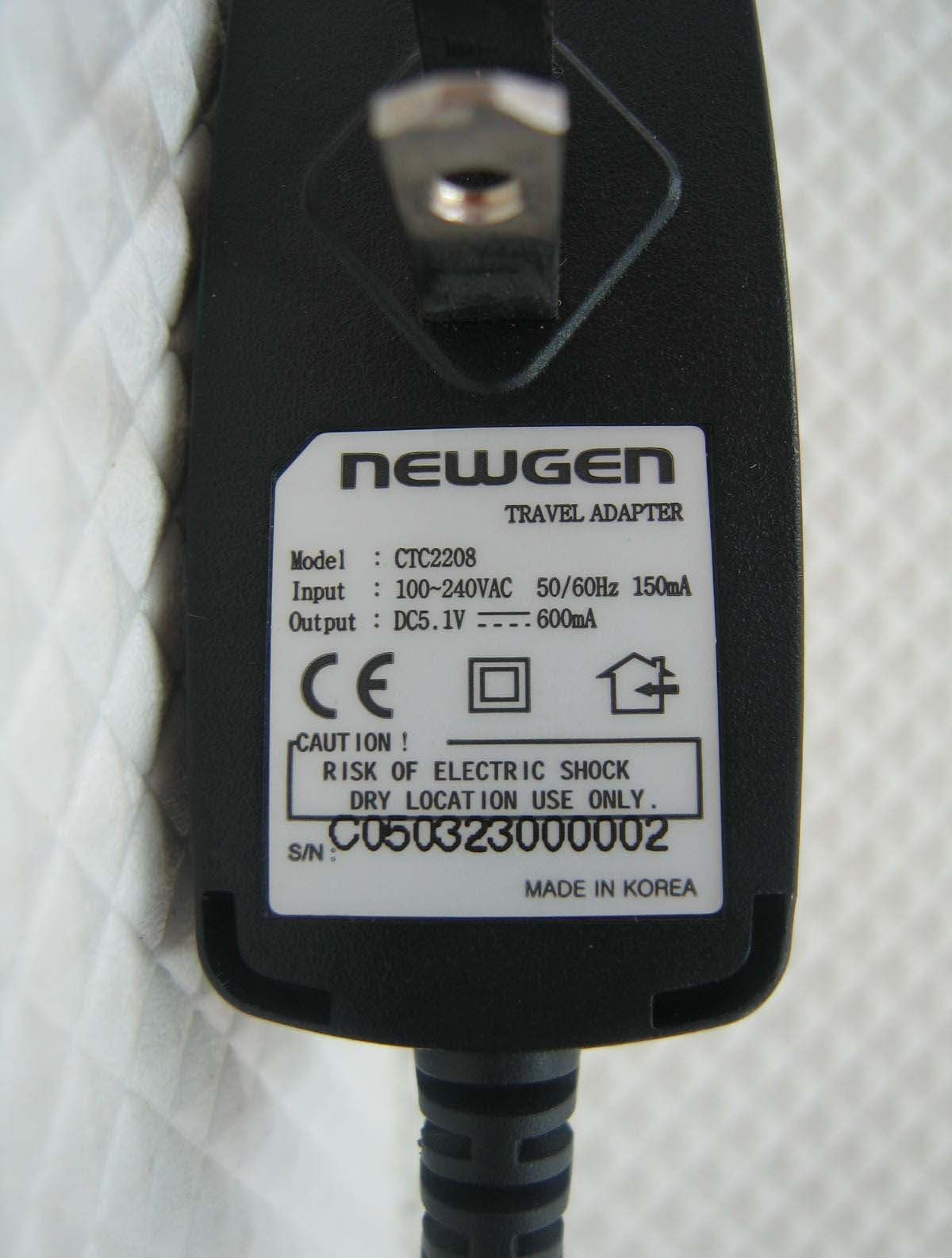
Label Label Location
Internal Photos
Internal Photos
RF Exposure Info
No. SAR06-001 Page 3 of 48 Contents 1. GENERAL CONDITIONS 2. ADMINISTRATIVE DATA 2.1. Identification of the Responsible Testing Laboratory 2.2. Identification of the Responsible Testing Location(s) 2.3. Organization Item 2.4. Identification of Applicant 2.5. Identification of Manufacture 3. EQUIPMENT UNDER TEST (EUT) 3.1. Identification of the Equipment under Test 3.2. Identification of all used Test Sample of the Equipment under Test 4. OPERATIONAL CONDITIONS DURING TEST 4.1. Schematic Test Configuration 4.2. SAR Measurement System 5. CHARACTERISTICS OF THE TEST 5.1. Applicable Limit Regulations 5.2. Applicable Measurement Standards 6. LABORATORY ENVIRONMENT 7. TEST RESULTS 7.1. Dielectric Performance 7.2. Summary of Measurement Results 7.3. Conclusion 8. MEASUREMENT UNCERTAINTY 9. MAIN TEST INSTRUMENTS This Test Report consists of the following Annexes: Annex A: Accreditation Certificate Annex B: Test Layout Annex C: Sample Photographs Annex D: Graph Test Results No. SAR06-001 Page 4 of 48 1GENERAL CONDITIONS 1.1 This report only refers to the item that has undergone the test. 1.2 This report standalone dose not constitute or imply by its own an approval of the product by the certification Bodies or competent Authorities. 1.3 This document is only valid if complete; no partial reproduction can be made without written approval of Shenzhen Electronic Product Quality Testing Center. 1.4 This report cannot be used partially or in full for publicity and/or promotional purposes without previous written approval of Shenzhen Electronic Product Quality Testing Center and the Accreditation Bodies, if it applies. No. SAR06-001 Page 5 of 48 2. Administrative Date 2.1. Identification of the Responsible Testing Laboratory Company Name: ShenZhen Electronic Product Quality Testing Center Department: Testing Department Address: Electronic Testing Building, ShaHe Road, NanShan District, ShenZhen, P. R. China Telephone: +86-755-26628676 Fax: +86-755-26627238 Responsible Test Lab Managers: Mr. Wang Keqin 2.2. Identification of the Responsible Testing Location(s) Company Name: ShenZhen Electronic Product Quality Testing Center Address: Electronic Testing Building, ShaHe Road, NanShan District, ShenZhen, P. R. China 2.3. Organization Item S.E.T Report No.: SAR06_001 S.E.T Project Leader: Mr. Li Sixiong S.E.T Responsible for accreditation scope: Mr. Wang Keqin Start of Testing: 2005-12-29 End of Testing: 2005-12-31 2.4. Identification of Applicant Company Name: Newgen Telecom Co.,LTD Address: 7th FI.,SamYoung, 106-2, Banpo-Dong, Seocho-gu Seoul, 137-040 Korea Contact person: Henry Chen Telephone: 86-13911785721 Fax: 86-10-84505006 2.5. Identification of Manufacture Company Name: Newgen Telecom Co.,LTD Address: 7th FI.,SamYoung, 106-2, Banpo-Dong, Seocho-gu Seoul, 137-040 Korea Contact person: Henry Chen Telephone: 86-13911785721 Fax: 86-10-84505006 Notes: This data is based on the information by the applicant. No. SAR06-001 Page 6 of 48 3. Equipment Under Test (EUT) 3.1. Identification of the Equipment under Test Brand Name: NEWGEN Type Name: T1400 Marking Name: T1400 Test frequency PCS 1900MHz Battery type 674M0100BAF Battery specification 710mAh 3.7V Li-ion Antenna specification Build inside Operation mode Call established Modulation mode GSM; NO BLUETOOTH General description: Max. Power(EIRP) 0.243w(23.86dBm) 3.2. Identification of all used Test Sample of the Equipment under Test EUT Code type Hardware Version Software Version IMEI 02110d01 Product unit P5.7_R01.17 P3.0 000000000000000 No. SAR06-001 Page 7 of 48 4 OPERATIONAL CONDITIONS DURING TEST 4.1 Schematic Test Configuration During SAR test, EUT is in Traffic Mode (Channel Allocated) at Normal Voltage Condition. A communication link is set up with a System Simulator (SS) by air link, and a call is established. The TCH is allocated to 512, 661 and 810 respectively in the case of PCS 1900 MHz. The EUT is commanded to operate at maximum transmitting power. The EUT shall use its internal transmitter. The antenna(s), battery and accessories shall be those specified by the manufacturer. The EUT battery must be fully charged and checked periodically during the test to ascertain uniform power output. If a wireless link is used, the antenna connected to the output of the base station simulator shall be placed at least 50 cm away from the handset. The signal transmitted by the simulator to the antenna feeding point shall be lower than the output power level of the handset by at least 35 dB. 4.2 SAR Measurement System The SAR measurement system being used is the IndexSAR SARA2 system, which consists of a Figure1. SAR Lab Test Measurement Set-up Mitsubishi RV-E2 6-axis robot arm and controller, IndexSAR probe and amplifier and SAM phantom No. SAR06-001 Page 8 of 48 Head Shape. The system is controlled remotely from a PC, which contains the software to control the robot and data acquisition equipment. The software also displays the data obtained from test scans, and determine the averaged SAR values (averaging region 1 gram or 10 gram) for compliance testing. The measurements are done by two scan: first a coarse scan (2-Division) determines the region of the maximum SAR, afterwards the averaged SAR is measured in a second san within the shape of a cube. The measurement time takes about 20 minutes. 4.2.1 Robot system specification The robot is used to articulate the probe to programmed positions inside the phantom head to obtain the SAR readings from the DUT. 4.2.2 Probe and amplifier specification IXP-050 Indexsar isotropic immersible SAR probe The probes are constructed using three orthogonal dipole sensors arranged on an interlocking, triangular prism core. The probes have built-in shielding against static charges and are contained within a PEEK No. SAR06-001 Page 9 of 48 cylindrical enclosure material at the tip (showed in figure 2). The system uses diode compression potential (DCP) to determine SAR values for different types of modulation. Crest factor is no…
Text truncated - open the document above for the full version.
Test Report
Report No. FCC06-8001 Page 2 of 41 Table of Contents 1 Test Report Certification ...............................................................................................................4 2 General Information ......................................................................................................................5 2.1 Description of EUT ...............................................................................................................5 2.2 Objective ...............................................................................................................................6 2.3 Test Standards and Results ....................................................................................................6 2.4 List of Equipments Used .......................................................................................................7 2.5 Test Facility ...........................................................................................................................7 2.6 Environmental Conditions ....................................................................................................7 3 Conducted Emission Measurement...............................................................................................8 3.1 Limits of Conducted Emission..............................................................................................8 3.2 Test Procedure .......................................................................................................................8 3.3 Test Setup ..............................................................................................................................9 3.4 EUT Setup and Operating Conditions...................................................................................9 3.5 Test Results ...........................................................................................................................9 4 Radiated Emission Test ............................................................................................................... 11 4.1 Limits of Radiated Emission ............................................................................................... 11 4.2 Test Procedure ..................................................................................................................... 11 4.3 Test Setup ............................................................................................................................12 4.4 EUT Setup and Operating Conditions.................................................................................12 4.5 Test Results .........................................................................................................................12 5 Frequencies .................................................................................................................................14 5.1 Frequency Blocks Available for Broadband PCS ...............................................................14 5.2 Test Procedure .....................................................................................................................14 5.3 Test Setup ............................................................................................................................15 5.4 EUT Setup and Operating Conditions.................................................................................15 5.5 Test Results .........................................................................................................................15 6 Equivalent Isotropically Radiated Power (EIRP) Test ................................................................17 6.1 Limits of EIRP ....................................................................................................................17 Report No. FCC06-8001 Page 3 of 41 6.2 Test Procedure .....................................................................................................................17 6.3 Test Setup ............................................................................................................................17 6.4 EUT Setup and Operating Conditions.................................................................................17 6.5 Test Results .........................................................................................................................17 7 Occupied Bandwidth ...................................................................................................................18 7.1 Definition ............................................................................................................................18 7.2 Test Procedure .....................................................................................................................18 7.3 Test Setup ............................................................................................................................18 7.4 EUT Setup and Operating Conditions.................................................................................18 7.5 Test Results .........................................................................................................................19 8 Conducted Spurious Emission Test.............................................................................................21 8.1 Limits of Conducted Spurious Emission.............................................................................21 8.2 Test Procedure .....................................................................................................................21 8.3 Test Setup ............................................................................................................................21 8.4 EUT Setup and Operating Conditions.................................................................................21 8.5 Test Results .....................................................................................…
Text truncated - open the document above for the full version.
Contact Information
Applicant
Choon-Gyum Kim(Director)
Test Firm
ShenZhen Electronic Product Quality Testing CenterXingsun Lin
Technical Specifications
| # | Rule Parts | Frequency Range | Power Output | Emission | Tolerance |
|---|---|---|---|---|---|
| 1 | 24E | 1.85 GHz - 1.91 GHz | 243.00 mW | 300KGXW | 0.1000000000 ppm |
Other Applications from NewGen Telecom. Co., Ltd.
R5WNGTE1300
Aug 20, 2006Dual-Band GSM 900 / 1900 MHz Mobile Phone
Equipment Class
PCE - PCS Licensed Transmitter held to ear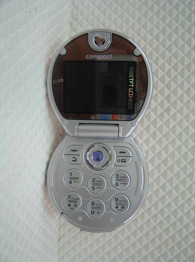
R5WNGTC1500
Jan 22, 2006Dual-Band GSM 900/1900 MHz Mobile Phone
Equipment Class
PCE - PCS Licensed Transmitter held to ear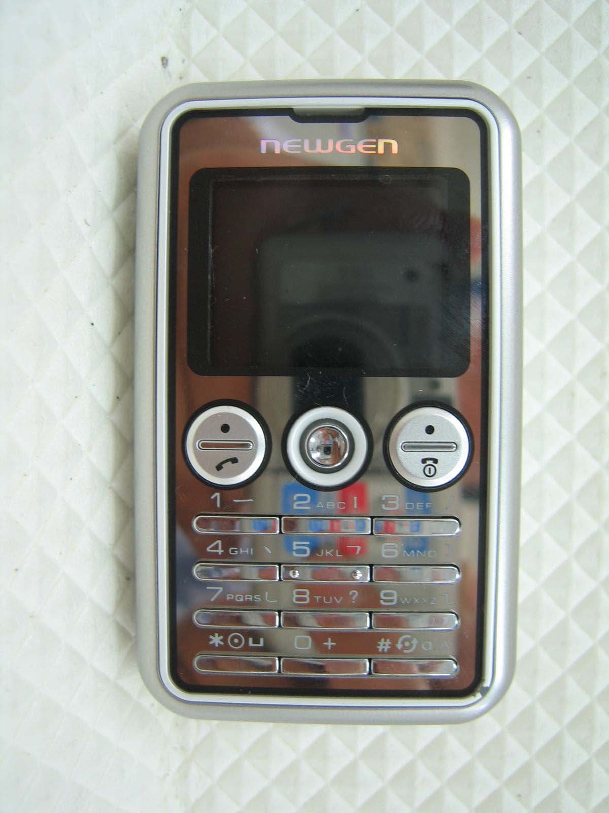
R5WNGTE1400
Jan 09, 2006Dual-band GSM phone GSM850/PCS1900
Equipment Class
PCE - PCS Licensed Transmitter held to ear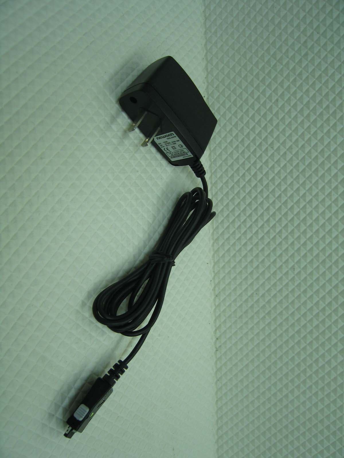
R5WNGTN551
Apr 10, 2005Tri-band GSM phone GSM850/DCS1800/PCS1900
Equipment Class
PCE - PCS Licensed Transmitter held to ear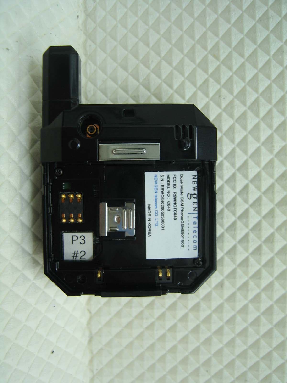
R5WNGTC640
Apr 10, 2005Tri-band GSM phone GSM850/DCS1800/PCS1900
Equipment Class
PCE - PCS Licensed Transmitter held to ear