R5XBACKSENSEBrigade Backsense Radar
Brigade Electronics Group Plc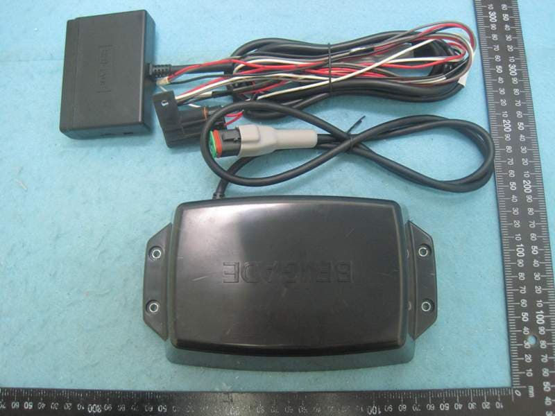
Click to zoom
Application Details
- Equipment Class
- DXX - Part 15 Low Power Communication Device Transmitter
- Date of Grant
- Mar 16, 2014
- Application Purpose
- Original Equipment
- Date of Application
- Mar 16, 2014
- Equipment Note
- Brigade Backsense Radar
- Frequency Range
- 24068.00000000 - 24218.00000000
- Country
- United Kingdom
Documents & Files
Document Text
Text extracted from the exhibit documents filed with the FCC. Open a document above to read the original.
Users Manual
Brigade Backsense® Installation Guide v1.2 (4555) Page 1 Installation Guide Backsense® Radar Obstacle Detection Systems Models: BS-8000, BS-7030, BS-7045, BS-7060 Brigade Backsense® Installation Guide v1.2 (4555) Page 2 Contents Page 1.0 Introduction 3 1.1 System Functionality 3 1.2 Detection Distances 3 2.0 System Components 4 3.0 Hardware Installation 4 3.1 Installation Site 4 3.2 Sensor Mounting 4 3.3 Display Mounting 4 3.4 Cable 5 4.0 Initial System Power Up and Test 5 5.0 Configurable System - BS-8000 5 5.1 Configuration Tool software installation 5 5.1.1 System requirements 6 5.1.2 UI Overview 6 5.1.3 Main Menu 6 5.2 Connecting to the system 6 5.2.1 Com Port 7 5.2.2 Connect Sensor 7 5.3 Detection Zone Setup 7 5.3.1 View Detection Zone 8 5.3.2 Setup Detection Zone 8 5.3.3 Detection Area Length 9 5.3.3.1 Detection Zone Length setup 9 5.3.3.2 Quick Zones Detection Area Length (D.A.L.) 9 5.3.3.3 Detection Zone Width 9 5.3.3.4 Trigger Output Length 10 5.3.3.5 Buzzer Starting Zone 10 5.3.4 Blind zone setup 11 5.3.4.1 Selecting blind zone cells 12 5.3.5 Writing settings to display 12 Appendix I – System Connectivity 15 Appendix II – Configuration Tool software installation 16 Appendix III – Daily Maintenance 20 Appendix IV – Specifications 21 Appendix V - Mounting Dimensions 22 Appendix VI FCC Statement: 23 Brigade Backsense® Installation Guide v1.2 (4555) Page 3 1.0 Introduction Brigade’s Backsense FMCW radar systems are designed to detect people and objects in blind spots, significantly reducing accidents. They detect stationary and moving objects, providing the driver with in-cab visual and audible warnings – alerting the operator whose attention cannot be focused on all danger areas. Backsense works effectively in harsh environments and in poor visibility including darkness, smoke and fog. It is imperative that Brigade Backsense® is fitted and commissioned by competent and trained technicians. The installer is responsible for the fitness for purpose of the overall system and adheres to relevant regulations and legislation. Operators of the vehicle to which the Brigade Backsense® system is fitted must be made fully aware of how to interpret the system so they will not be distracted by or rely completely on it. Distraction can cause accidents. The system is intended to aid the operator, who must still concentrate on operating the vehicle, obey traffic and local regulations and continue to use his/her own training, senses and other vehicle aids, such as mirrors, as would be done if the system were not in place. Nothing removes the responsibility of the operator to operate the vehicle in a proper and lawful manner. 1.1 System Functionality The Brigade Backsense® uses Frequency Modulated Continuous Wave (FMCW). FMCW differs from pulsed radar in that an electromagnetic signal that is continuously transmitted. The frequency of the signal changes over time, generally in a sweep across a set bandwidth. Backsense® bandwidth is 24.068 – 24.218GHz. 1.2 Detection Distances The four available systems are as follows: * - Default settings Model (Part No.) Length (m) Each Zone Length (m) Width (m) Minimum Tolerance (m) BS-7030 (4527) 3.0 0.6 2.5 ±0.25 BS-7045 (4528) 4.5 0.9 3.5 ±0.25 BS-7060 (4529) 6.0 1.2 4.5 ±0.25 BS-8000 (4530) 3.0 – 30.0 *(10.0) 1.0 – 26.0 *(2.0m) 2.0 – 10.0 *(7.0m) ±0.75 BS-7030, 7045 & 7060 have fixed detection length and width divided into five equal detection zones. The buzzer and trigger output activate in all zones on detection. Stationary objects are detected from the start of the detection area up to 1.2m of the sensor. Any stationary object will not be detected inside 1.2m – 0.2m of the sensor unless the object or vehicle moves; detection to alert will take less than 0.2sec. Any object closer than 0.3m will not be detected. The BS-8000 uses the same fundamental operation as all the above systems but detection zone, blind zone, trigger length and buzzer starting zone are all configurable. Refer to section 5.0. Brigade Backsense® Installation Guide v1.2 (4555) Page 4 x4 2.0 System Components Sensor Display Extension Cable Fixing Kit Configurable system: as above and including Software CD Mini USB Cable 3.0 Hardware Installation Refer to the vehicle manufacturers bodybuilder guidelines for installation procedures and connectivity in all applications. Ensure the positive connections are fused at source. System connections are shown in the table below. Connect red and black to ignition and ground, grey connected to the activating trigger (e.g. reverse) and white is a ground output trigger which is active under detection (customisable on the BS-8000 system). System Connections RED Ignition +12/24v BLACK Ground GREY Activation trigger WHITE Ground trigger output 3.1 Installation Site The installation site, for calibration purposes, must be relatively flat without excessive deviation. Flat does not necessarily mean level; a sloping flat area may be acceptable as long as the vehicle does not lean excessively. 3.2 Sensor Mounting The sensor should be mounted in the upright position (Brigade logo in normal orientation) avoiding detection of the ground and any vehicle furniture where possible. This is critical on the non-configurable systems where obstacles can be ignored in the configurable system. The horizontal angle of the detection zone is 110° ±10°.and the vertical 12°±2°. [INSERT DIAGRAMS CONTAINING DETECTION PATTERNS] SYSTEM SENSOR DISPLAY CABLE SOFTWARE CONNECTIVITY BS-7030 (4527) BS-7XXXS (4542) BS-7030D (4531) BS-09DCX (4551) - - BS-7045 (4528) BS-7XXXS (4542) BS-7045D (4532) - - BS-7060 (4529) BS-7XXXS (4542) BS-7060D (4533) - - BS-8000 (4530) BS-8000S-S BS-8000D (4534) CD (4553) USB CBL (4554) Brigade Backsense® Installation Guide v1.2 (4555) Page 5 Horizontal Detection Vertical detection 3.3 Display The display should be mounted where the vehicle operator has good visibility in all environments. The display should be fixed in a suitable location in line with any current…
Text truncated - open the document above for the full version.
External Photos
Report No.: 3N1469 SPORTON International Inc. PAGE NUMBER : 1 OF 3 TEL : 886-3-327-3456 ISSUED DATE : Dec. 13, 2013 FAX : 886-3-327-0973 Photographs of EUT Report No.: 3N1469 SPORTON International Inc. PAGE NUMBER : 2 OF 3 TEL : 886-3-327-3456 ISSUED DATE : Dec. 13, 2013 FAX : 886-3-327-0973 Report No.: 3N1469 SPORTON International Inc. PAGE NUMBER : 3 OF 3 TEL : 886-3-327-3456 ISSUED DATE : Dec. 13, 2013 FAX : 886-3-327-0973
Internal Photos
Report No.: 3N1469 SPORTON International Inc. PAGE NUMBER : 1 OF 16 TEL : 886-3-327-3456 ISSUED DATE : Dec. 13, 2013 FAX : 886-3-327-0973 Photographs of EUT Report No.: 3N1469 SPORTON International Inc. PAGE NUMBER : 2 OF 16 TEL : 886-3-327-3456 ISSUED DATE : Dec. 13, 2013 FAX : 886-3-327-0973 Report No.: 3N1469 SPORTON International Inc. PAGE NUMBER : 3 OF 16 TEL : 886-3-327-3456 ISSUED DATE : Dec. 13, 2013 FAX : 886-3-327-0973 Report No.: 3N1469 SPORTON International Inc. PAGE NUMBER : 4 OF 16 TEL : 886-3-327-3456 ISSUED DATE : Dec. 13, 2013 FAX : 886-3-327-0973 Report No.: 3N1469 SPORTON International Inc. PAGE NUMBER : 5 OF 16 TEL : 886-3-327-3456 ISSUED DATE : Dec. 13, 2013 FAX : 886-3-327-0973 Report No.: 3N1469 SPORTON International Inc. PAGE NUMBER : 6 OF 16 TEL : 886-3-327-3456 ISSUED DATE : Dec. 13, 2013 FAX : 886-3-327-0973 Report No.: 3N1469 SPORTON International Inc. PAGE NUMBER : 7 OF 16 TEL : 886-3-327-3456 ISSUED DATE : Dec. 13, 2013 FAX : 886-3-327-0973 Report No.: 3N1469 SPORTON International Inc. PAGE NUMBER : 8 OF 16 TEL : 886-3-327-3456 ISSUED DATE : Dec. 13, 2013 FAX : 886-3-327-0973 Report No.: 3N1469 SPORTON International Inc. PAGE NUMBER : 9 OF 16 TEL : 886-3-327-3456 ISSUED DATE : Dec. 13, 2013 FAX : 886-3-327-0973 Report No.: 3N1469 SPORTON International Inc. PAGE NUMBER : 10 OF 16 TEL : 886-3-327-3456 ISSUED DATE : Dec. 13, 2013 FAX : 886-3-327-0973 Report No.: 3N1469 SPORTON International Inc. PAGE NUMBER : 11 OF 16 TEL : 886-3-327-3456 ISSUED DATE : Dec. 13, 2013 FAX : 886-3-327-0973 Report No.: 3N1469 SPORTON International Inc. PAGE NUMBER : 12 OF 16 TEL : 886-3-327-3456 ISSUED DATE : Dec. 13, 2013 FAX : 886-3-327-0973 Report No.: 3N1469 SPORTON International Inc. PAGE NUMBER : 13 OF 16 TEL : 886-3-327-3456 ISSUED DATE : Dec. 13, 2013 FAX : 886-3-327-0973 Report No.: 3N1469 SPORTON International Inc. PAGE NUMBER : 14 OF 16 TEL : 886-3-327-3456 ISSUED DATE : Dec. 13, 2013 FAX : 886-3-327-0973 Report No.: 3N1469 SPORTON International Inc. PAGE NUMBER : 15 OF 16 TEL : 886-3-327-3456 ISSUED DATE : Dec. 13, 2013 FAX : 886-3-327-0973 Report No.: 3N1469 SPORTON International Inc. PAGE NUMBER : 16 OF 16 TEL : 886-3-327-3456 ISSUED DATE : Dec. 13, 2013 FAX : 886-3-327-0973
Test Report
SPORTON International Inc. No. 52, Hwa Ya 1st Rd., Hwa Ya Technology Park, Kwei-Shan Hsiang, Tao Yuan Hsien, Taiwan, R.O.C. Ph: 886-3-327-3456 / FAX: 886-3-327-0973 / www.sporton.com.tw Report Format Version: 03 FCC RADIO TEST REPORT Applicant’s company BRIGADE ELECTRONICS PLC Applicant Address Brigade House, The Mills, Station Road, South Darenth, Kent, DA4 9BD United Kingdom FCC ID R5XBACKSENSE Manufacturer’s company Wistron Neweb Corporation Manufacturer Address 20 Park Avenus II, Hsinchu Science Park, Hsinchu 308, Taiwan, R.O.C. Product Name Brigade Backsense Radar Brand Name BRIGADE Model Name BS-7030, BS-7045, BS-7060, BS-8000, BS-XXXX, BS-XXXX-X Test Rule Part(s) 47 CFR FCC Part 15 Subpart C § 15.249 Test Freq. Range 24000 ~ 24250MHz Received Date Nov. 14, 2013 Final Test Date Nov. 21, 2013 Submission Type Original Equipment Statement The test result in this report refers exclusively to the presented test model / sample. Without written approval of SPORTON International Inc., the test report shall not be reproduced except in full. The measurements and test results shown in this test report were made in accordance with the procedures and found in compliance with the limit given in ANSI C63.10-2009 and 47 CFR FCC Part 15 Subpart C. The test equipment used to perform the test is calibrated and traceable to NML/ROC. Report No.: FR3N1469 Report Format Version: 03 Page No. : i of ii FCC ID: R5XBACKSENSE Issued Date : Dec. 18, 2013 Table of Contents 1 CERTIFICATE OF COMPLIANCE ......................................................................................................................... 1 2 SUMMARY OF THE TEST RESULT .......................................................................................................................... 2 3 GENERAL INFORMATION .................................................................................................................................. 3 3.1 Product Details....................................................................................................................................................................................3 3.2 Table for Carrier Frequencies .............................................................................................................................................................3 3.3 Table for Test Modes ...........................................................................................................................................................................3 3.4 Table for Testing Locations..................................................................................................................................................................4 3.5 Table for Multiple Listing......................................................................................................................................................................4 3.6 Table for Supporting Units ...................................................................................................................................................................4 3.7 Test Configurations .............................................................................................................................................................................5 4 TEST RESULT ..................................................................................................................................................... 7 4.1 Field Strength of Fundamental Emissions Measurement .....................................................................................................................7 4.2 20dB Spectrum Bandwidth Measurement ........................................................................................................................................12 4.3 Radiated Emissions Measurement ....................................................................................................................................................15 4.4 Band Edge Emissions Measurement .................................................................................................................................................33 4.5 Antenna Requirements .....................................................................................................................................................................35 5 LIST OF MEASURING EQUIPMENTS ................................................................................................................... 36 6 TEST LOCATION.............................................................................................................................................. 38 7 MEASUREMENT UNCERTAINTY.......................................................................................................................... 39 APPENDIX A. TEST PHOTOS ........................................................................................................................ A1 ~ A4 Report No.: FR3N1469 Report Format Version: 03 Page No. : ii of ii FCC ID: R5XBACKSENSE Issued Date : Dec. 18, 2013 History of This Test Report REPORT NO. VERSION DESCRIPTION ISSUED DATE FR3N1469 Rev. 01 Initial issue of report Dec. 12, 2013 FR3N1469 Rev. 02 1. Changing the brand name 2. Adding a model name “BS-XXXX-X” Dec. 13, 2013 FR3N1469 Rev. 03 Revise test setup layout in section 4.3.4. Dec. 18, 2013 47 CFR FCC Part 15 Subpart C 2.7 15.209(a) Further, this requirement does not apply to intentional radiators that must be professionally installed. Report No.: FR3N1469 Report Format Version: 03 Page No. : 2 of 41 FCC ID: R5XBACKSENSE Issued Date : Dec. 18, 2013 2 SUMMARY OF THE TEST RESULT Applied Standard: 47 CFR FCC Part 15 Subpart C Part Rule Section Description of Test Result Under Limit - 15.207 AC Power Line Conducted Emissions - Note 1 4.1 15.249(a) Field Strength of Fundamental Emissions Complies 1.33 dB 4.2 15.215(c) 20dB Spectrum Bandwidth Complies - 4.3 15.249…
Text truncated - open the document above for the full version.
Test Setup Photos
Report No.: FR3N1469 FCC ID: R5XBACKSENSE Page No. : A1 of A4 Appendix A. Test Photos Report No.: FR3N1469 FCC ID: R5XBACKSENSE Page No. : A2 of A4 1. Photographs of Radiated Emissions Test Configuration Test Configuration: 9kHz ~30MHz FRONT VIEW REAR VIEW Report No.: FR3N1469 FCC ID: R5XBACKSENSE Page No. : A3 of A4 Test Configuration: 30MHz~1GHz FRONT VIEW REAR VIEW Report No.: FR3N1469 FCC ID: R5XBACKSENSE Page No. : A4 of A4 Test Configuration: Above 1GHz FRONT VIEW REAR VIEW
Contact Information
Applicant
Bernd John(GHoRDT)
Test Firm
Sporton International Inc.Alex Chen
Technical Specifications
| # | Rule Parts | Frequency Range | Power Output |
|---|---|---|---|
| 1 | 15C | 24.07 GHz - 24.22 GHz | - |
Other Applications from Brigade Electronics Group Plc

R5XDC200AI
Jun 27, 2023AI Dash Camera
Equipment Class
PCB - PCS Licensed Transmitter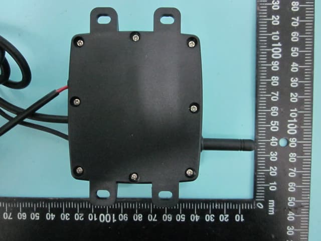
R5XDW1001RX001
Feb 05, 2013Digital Wireless System
Equipment Class
DSS - Part 15 Spread Spectrum Transmitter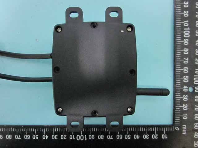
R5XDW1001TX001
Feb 04, 2013Digital Wireless System
Equipment Class
DSS - Part 15 Spread Spectrum Transmitter