Text extracted from the exhibit documents filed with the FCC. Open a document above to read the original.
Place sensors around the home and attach key fob. > Peel off paper from each sensor to expose adhesive before attaching. Place each sensor on the appropriate object according to its label (for example, “refrigerator”). Refrigerator Sensor* See diagram at right. Key Fob Sensor Attach to the keys you use most often. Attach Pillbox Sensor so that the adhesive adheres to the bottom and side of the pillbox case. Be sure to keep this product code for future reference Attach Refrigerator Sensor to the outside of the refrigerator door (top, bottom, or side). For help and support: 888-757-0711 [email protected] To see a tutorial video about Lively setup: www.mylively.com/videos Go to mylively.com and enter your unique 6-digit code to activate Lively and complete a one-time setup. > Go online via computer, tablet, or smartphone, and you will: 1) Activate the Lively hub and sensors 2) Set up a Lively account 3) Choose daily routine preferences 4) Enter information for your monthly Lively subscription Don’t have a computer? No problem. After you’ve plugged in the Lively hub, simply ask a family member or friend to complete this step for you and provide them with the 6-digit code below. Or contact us and we will help activate your Lively. Custom Sensor* Place on any movable object that is part of your daily routine (e.g., phone receiver, bathroom door, or favorite chair). Kitchen Sensor* Place on a frequently used item in the kitchen (e.g., pantry door, microwave door, or utensil drawer). Plug in Lively hub in or near the kitchen. Make sure the location you choose for the hub is in a direct line of sight with the refrigerator. > Insert one end of the power adapter (found in bottom of Lively box) into the Lively hub and the other end into a wall socket. Lively’s status light will blink green for up to three minutes, then change to solid green. Make sure you see at least one orange bar next to the green status light. Pillbox 1 Sensor See diagram at right. Pillbox 2 Sensor If you have a second pillbox, see diagram at right. Setting Up Your Live!y Ò A Quick Start Guide *Make sure the sensor does not obstruct the opening or closing of the object. Although Lively sensors are water resistant, avoid placing the units in direct contact with water. Lively Limited Warranty Hamlet Inc., dba “Lively” (“Lively”) warrants to the original purchaser that its sensor and hub hardware (excluding batteries, the “Equipment”) will be free of any defect in material and workmanship according to the terms and conditions of this Limited Warranty (“Limited Warranty”). For purposes of this Limited Warranty, the original purchaser is deemed to be the original end user of the Equipment purchased. This Limited Warranty is valid only for the original purchaser and is NONTRANSFERABLE and UNASSIGNABLE. For How Long: This Limited Warranty covers the Equipment for twelve (12) months from the date of the original shipment to the original purchaser for Equipment. Batteries are not covered by this Limited Warranty. The terms of the Limited Warranty in effect as of the date of original purchase will apply to any warranty claims. How to Initiate Warranty Service: To obtain warranty service for your Equipment, call toll free (888) 757-0711 or email support@ mylively.com. We will try to resolve your issue over via phone and/or email and determine warranty coverage. If necessary, and at our sole discretion, we will arrange for service or a replacement of some or all of the Equipment. What We Will Do: Lively at its sole discretion will repair or replace the Equipment, provided the warranty applies and the warranty period has not expired. The repaired or replaced Equipment will be warranted subject to the terms and conditions of this Limited Warranty for either (a) 90 days or ( b) the remainder of the original warranty period, whichever is longer. THE SERVICE DESCRIBED IN THIS LIMITED WARRANTY IS LIVELY’S SOLE AND EXCLUSIVE OBLIGATION, AND YOUR SOLE AND EXCLUSIVE REMEDY, FOR ANY BREACH OF WARRANTY. Obligations and Warranty Limits: Limited Warranty Obligation: Exclusive Remedy THE FOREGOING LIMITED WARRANTY IS IN LIEU OF AND SPECIFICALLY EXCLUDES AND REPLACES ALL OTHER EXPRESSED OR IMPLIED WARRANTIES, INCLUDING, BUT NOT LIMITED TO, THE IMPLIED WARRANTIES OF MERCHANTABILITY AND FITNESS FOR A PARTICULAR PURPOSE. This Limited Warranty is Void if: 1. Any Lively Equipment is tampered with, modified, serviced or repaired by any person or entity other than Lively, unless specifically authorized in writing by Lively. 2. Any Lively Equipment case is opened by unauthorized personnel or if Equipment is used for an unauthorized purpose or contrary to the proper use as described in writing by Lively. 3. Any Lively Equipment is used in conjunction with incompatible products, parts or accessories, including but not limited to batteries. Products, parts and accessories are not compatible if they are not Lively products or products that Lively has expressly authorized for use with the Equipment. If the Warranty Period has Expired: If your Lively Equipment is not covered by our Limited Warranty, call toll free (888) 757-0711 or email [email protected] for advice as to whether we can repair your Equipment, and for other repair information, including charges. Charges for non-warranty repairs that you authorize will be billed to your account. Upon completion of the repair, the terms and conditions of this Limited Warranty shall apply to such repair or replacement Equipment for a period of 90 days. If Batteries Expire: Batteries are not covered by this Limited Warranty, and replacement is the purchaser’s responsibility. If your batteries expire, call toll free (888) 757-0711 or email [email protected] for advice as to replacement. This equipment has been tested and found to comply with the limits for a Class B digital device, pursuant to part 15 of the FCC Rules. This device complies with Part 15 of the FCC rules. Operation is subject to the following two cond…
Text truncated - open the document above for the full version.
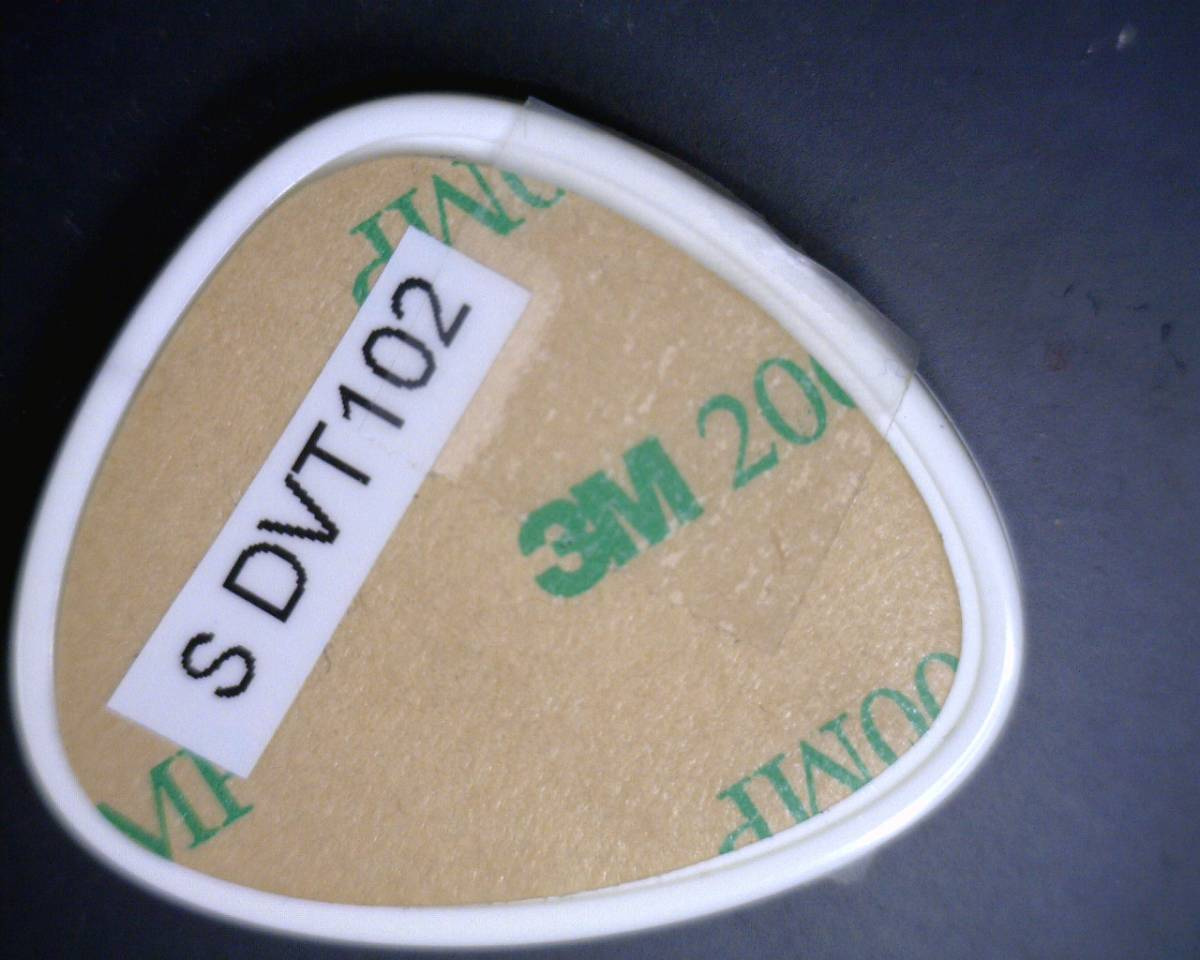
R6N-0002 External Product Photos Model: Lively 1.0 Top Side Rear Side
Label and Label Placement FCC ID: R6N-0002 Description: Bluet ooth Isolator Headset Model Name: LivelyHome System Model Number: Lively 1.0 Hamlet Inc. 682 Schofield Road San Francisco, CA 94129 By TEM Consulting, LP 140 River Rd. Georgetown, TX 78628 MAY 2013 DO NOT SCALE; ARTWORK PLACEMENT 1:1 TEXTURED IN TOOL CENTER ARTWORK RIGHT TO LEFT NO COLOR, TEXTURE ONLY Lively Sensor and Keyfob FCC ID Texture Guidelines042213rev.005 NOTES UNLESS OTHERWISE SPECIFIED 1 2 3 4 MID-PLANE 1 MID-PLANE 2 MID-PLANE 2 0.5mm offset from edge 0.5mm offset from edge
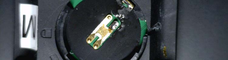
R6N-0002 Product Internal Photos Assembly Back-Side (Battery-Side) PC Board R6N-0002 Product Internal Photos RF Section
RF Exposure- Specific Absorption Rate (SAR) Project #: G101122982 Test Area: Intertek Louisville Test Method: FCC CFR47 Part 1.1310 Test Date: April-2013 EUT Model #: Lively 1.0 EUT Serial #: DVT101 Manufacturer: Hamlet, Inc. EUT Description: LivelyHome System Wireless Sensor – Low-Power DSS Notes: Sensor can be body-worn and/or < 20cm from user General SAR test reduction and exclusion guidance - KDB 447498 D01 General RF Exposure Guidance, May 28th, 2013 Standalone SAR test exclusion considerations Unless specifically required by the published RF exposure KDB procedures, standalone 1-g head or body and 10-g extremity SAR evaluation for general population exposure conditions, by measurement or numerical simulation, is not required when the corresponding SAR Test Exclusion Threshold condition, listed below, is satisfied. These test exclusion conditions are based on source-based time-averaged maximum conducted output power of the RF channel requiring evaluation, adjusted for tune-up tolerance, and the minimum test separation distance required for the exposure conditions. The minimum test separation distance is determined by the smallest distance from the antenna and radiating structures or outer surface of the device, according to the host form factor, exposure conditions and platform requirements, to any part of the body or extremity of a user or bystander (see 5) of section 4.1). To qualify for SAR test exclusion, the test separation distances applied must be fully explained and justified by the operating configurations and exposure conditions of the transmitter and applicable host platform requirements, typically in the SAR measurement or SAR analysis report, according to the required published RF exposure KDB procedures. When no other RF exposure testing or reporting is required, a statement of justification and compliance must be included in the equipment approval, in lieu of the SAR report, to qualify for the SAR test exclusion. When required, the device specific conditions described in the other published RF exposure KDB procedures must be satisfied before applying these SAR test exclusion provisions; for example, handheld PTT two-way radios, handsets, laptops & tablets etc. Maximum conducted and radiated power should both be taken into consideration to establish the worst case aggregate maximum output power. Test exclusion is applied to the required test channels on a channel by channel basis. Test Methodology The purpose of this document is to demonstrate the RF Exposure Safety of Radiation harmfulness to the human body for the product. The Gain of the antenna used in this product has been declared by the manufacturer and/or taken directly from the antenna specification sheet. EUT Operation The software provided by Manufacturer enabled the EUT to transmit data at lowest, middle and highest channel individually. Classification The antenna of the product, under normal use condition, is minimum 2.1 cm away from the body of the user. A warning statement to the user for keeping at least 2.1 cm or more separation distance with the antenna should be included in users manual. This device is classified as a Portable Device. SAR Exclusion Limit Criteria – Numeric Threshold The following limit is from FCC KDB 447498. Refer to Appendix A of this report for details. RF Exposure SAR Exclusion Threshold: ≤ 3.0 (1-g head/body) Determination of SAR Test Exclusion Threshold Minimum Test Separation Distance Manufacturer Statement: "For the low power exclusion calculation here are the dimensions that set the guaranteed minimum separation distance between the user and the TX antenna: The result of the mechanical team’s review of the Lively keyfob assembly was that the smallest nominal distance between the antenna and the exterior surface was: 2.14mm of plastic + air gap There is typically 0.5mm of gap between antenna and board edge So the nominal separation distance is 2.14 mm + 0.5 mm = 2.64 mm However, the minimum distance over production variability, if all tolerance stack worst case the absolute smallest possible distance is 2.1 mm." The following calculation was used to determine compliance to the above limit. The following is from FCC KDB 447498 D01 General RF Exposure Guidance, May 28th, 2013. 1. The 1-g and 10-g SAR test exclusion thresholds for 100 MHz to 6 GHz at test separation distances ≤ 50 mm are determined by: [(max. power of channel, including tune-up tolerance, mW) / (min. test separation distance, mm)] * [√f(GHz)] ≤ 3.0 for 1-g SAR and ≤ 7.5 for 10-g extremity Where f(GHz) is the RF channel transmit frequency in GHz Power and distance are rounded to the nearest mW and mm before calculation The result is rounded to one decimal place for comparison The test exclusions are applicable only when the minimum test separation distance is ≤ 50 mm and for transmission frequencies between 100 MHz and 6 GHz. Note: When the minimum test separation distance is < 5 mm, a distance of 5 mm is applied to determine SAR test exclusion. ==================================================================== S = (P/D) * √ f Where: S = SAR test exclusion threshold (1-g or 10-g) P = max power input to the antenna (mW) f = frequency (GHz) D = test separation distance to the center of radiation of the antenna (cm) Low-Power DSS 2.4GHz Radio Maximum conducted output power to antenna = 2.81mW (see test report 101122982DEN-002) Lowest Channel: 2.402GHz Highest Channel: 2.480GHz Minimum Test Separation Distance: 2.1mm Final Calculations: Actual minimum test distance = 2.1mm per manufacturer = 2.0mm (rounded to nearest mm). Per guideline above, when minimum test separation distance is < 5mm, a distance of 5 mm is applied to determine SAR test exclusion. Maximum measured conducted output power = 2.81mW = 3.0mW (rounded to nearest mW - per guideline ) Using worst-case 1-g head/body test exclusion limit (numeric threshold) of 3.0 Low Channel {Max Power of channel mW) / (Min test separation distan…
Text truncated - open the document above for the full version.
EMC Report for Hamlet, Inc. on the Model: Lively 1.0 Sensor Page 1 of 81 TEST REPORT Report Number: 101122982DEN-002 Project Number: G101122982 Report Issue Date: 5/17/2013 Product Designation: Model: Lively 1.0 Sensor Standards: FCC 47 CFR Part 15.247 RSS-210:2010 RSS-GEN:2010 Tested by: Client: Intertek Testing Services NA, Inc. 1795 Dogwood St. Suite 200 Louisville, CO 80027 Hamlet, Inc. 682 Schofield Road San Francisco, CA 94129 Report prepared by Report reviewed by Randy Thompson Senior EMC Project Engineer Mike Spataro Engineering Team Leader This report is for the exclusive use of Intertek's Client and is provided pursuant to the agreement between Intertek and its Client. Intertek's responsibility and liability are limited to the terms and conditions of the agreement. Intertek assumes no liability to any party, other than to the Client in accordance with the agreement, for any loss, expense or damage occasioned by the use of this report. Only the Client is authorized to permit copying or distribution of this report and then only in its entirety. Any use of the Intertek name or one of its marks for the sale or advertisement of the tested material, product or service must first be approved in writing by Intertek. The observations and test results in this report are relevant only to the sample tested. This report by itself does not imply that the material, product, or service is or has ever been under an Intertek certification program. Intertek Report Number: 101122982DEN-002 Issued:5/17/13 EMC Report for Hamlet, Inc. on the Model: Lively 1.0 Sensor Page 2 of 81 TABLE OF CONTENTS 1 Introduction and Conclusion .............................................................................................................. 3 2 Test Summary ...................................................................................................................................... 4 3 Description of Equipment Under Test ............................................................................................... 6 4 System setup including cable interconnection details, support equipment and simplified block diagram ........................................................................................................................................................ 7 5 Digital Modulation (DTS) ..................................................................................................................... 9 6 6dB Bandwidth (DTS Bandwidth)..................................................................................................... 10 7 Transmitter Output Power – EIRP Requirements ........................................................................... 16 8 Harmonics of the Fundamental (Out-of-Band Emissions) -20dBc ............................................... 20 9 Antenna Port Spurious Emissions 30MHz to 25GHz – Non-Restricted Bands (-20dBc & Band Edge) .......................................................................................................................................................... 25 10 Radiated Spurious Emissions 30MHz to 25GHz – Restricted Band & Band Edge .................. 34 11 Power Spectral Density (PSD)....................................................................................................... 59 12 Occupied Bandwidth (OBW) ......................................................................................................... 65 13 Receiver Emissions – Not Applicable .......................................................................................... 71 14 AC Mains Conducted Emissions – Not Applicable ..................................................................... 72 15 Duty Cycle Correction Factor – Not Used.................................................................................... 73 16 Antenna Requirement .................................................................................................................... 74 17 RF Exposure Requirements – SAR............................................................................................... 75 18 Measurement Uncertainty.............................................................................................................. 80 19 Revision History ............................................................................................................................. 81 Intertek Report Number: 101122982DEN-002 Issued:5/17/13 EMC Report for Hamlet, Inc. on the Model: Lively 1.0 Sensor Page 3 of 81 1 Introduction and Conclusion The tests indicated in section 2.0 were performed on the product constructed as described in section 3.0. The remaining test sections are the verbatim text from the actual data sheets used during the investigation. These test sections include the test name, the specified test Method, a list of the actual Test Equipment Used, documentation Photos, Results and raw Data. No additions, deviations, or exclusions have been made from the standard(s) unless specifically noted. Based on the results of our investigation, we have concluded the product tested complies with the requirements of the standard(s) indicated. The results obtained in this test report pertain only to the item(s) tested. Test Report Scope The scope of this report was to qualify the Lively 1.0 Wireless Sensor Unit – a Low-Power Sensor DSS radio product operating in the following transmit band: 2.4GHz to 2.4835 GHz. This product is a component of the LivelyHome System. The Hub (Master Unit) is a receiver-only product and was also fully tested – refer to the following Intertek report for details. 101122982DEN-001 General Test Methodology Both RF conducted port and radiated emissions measurements were performed according to the procedures in the following documents: ANSI C63.10:2009 – ANSI Standard for Testing Unlicensed Wireless Devices FCC Publication 558074: 2013 – “Guidance for Performing Compliance Measurements on Digital Transmission Systems (DTS) Opera…
Text truncated - open the document above for the full version.
R6N-0002 Test Setup Photos Setup Photographs: RF Conducted Port Measurements (Agilent EMC Receiver) R6N-0002 Test Setup Photos Setup Photographs: RF Conducted Port Measurements (R&S EMC Receiver) R6N-0002 Test Setup Photos Setup Photographs: Radiated Field Measurements Product Test Axis 1 – EUT Flat on Table Product Test Axis 2 – EUT Vertical Product Test Axis 3 – EUT Vertical & Rotated 90° R6N-0002 Test Setup Photos Setup Photographs: Radiated Field Measurements BiLog Antenna – 30MHz to 1000MHz Horn Antenna – 1GHz to 18GHz R6N-0002 Test Setup Photos Setup Photographs: Radiated Field Measurements HF Active Antenna – 18GHz to 26.5GHz
140 River Rd. · Georgetown, Texas · United States
| # | Rule Parts | Frequency Range | Power Output |
|---|---|---|---|
| 1 | 15C | 2.40 GHz - 2.48 GHz | 2.81 mW |

Lively Watch
Equipment Class
DTS - Digital Transmission System