R72IM400Private Land Mobile Radio for Vehicle (UHF)
E-TECH Co., Ltd.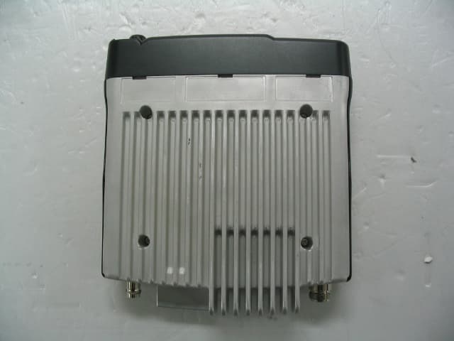
Click to zoom
Application Details
- Equipment Class
- TNB - Licensed Non-Broadcast Station Transmitter
- Date of Grant
- Dec 22, 2004
- Application Purpose
- Original Equipment
- Date of Application
- Dec 22, 2004
- Equipment Note
- Private Land Mobile Radio for Vehicle (UHF)
- Frequency Range
- 420.00000000 - 500.00000000
- Company
- E-TECH Co., Ltd.
- Country
- South Korea
Documents & Files
Document Text
Text extracted from the exhibit documents filed with the FCC. Open a document above to read the original.
Users Manual
E-Tech Co., Ltd. Installation requirements for compliance with Radio Frequency(RF) energy Exposure Safety Standards. [ Warning ] Your FM radio generates RF electromagnetic energy during transmit mode. This radio is designed for and classified as “Occupational Use Only”, meaning it must be used only during the course of employment by individuals aware of the hazards, and the ways to minimize such hazards. This radio is NOT intended for use by the “General Population” in an uncontrolled environment. This radio has been tested and complies with the FCC RF exposure limits for “Occupational Use Only.” In addition, your FM radio complies with the following standards and guidelines with regard to RF energy and electromagnetic energy levels and evaluation of such levels for exposure to humans : • FCC OET Bulletin 65 Edition 97-01 supplement C, Evaluating compliance with FCC guidelines for Human Exposure to Radio Frequency Electromagnetic Fields. • American National Standards Institute (C95.1-1992), IEEE standard for Safety levels with respect to human exposure to radio frequency electromagnetic fields, 3 kHz to 300 GHz. • American National Standards Institute (C95.3-1992), IEEE recommended practice for the measurement of potentially hazardous electromagnetic fields – RF and Microwave. • DO NOT operate the radio without a proper antenna attached, as this may damage the radio and may also cause you to exceed FCC RF exposure limits. A proper antenna is the antenna supplied with this radio by the manufacturer or an antenna specifically authorized by the manufacturer for use with this radio. • ALWAYS use E-TECH authorized accessories (antennas, batteries, speaker/mics, etc). Use of unauthorized accessories can cause the FCC RF exposure compliance requirements to be exceeded. • DO NOT transmit for more than 50% of total radio use time (50% duty cycle). Transmitting more than 50% of the time can cause FCC RF exposure compliance requirements to be exceeded. The radio is transmitting when the “TX Indicator” lights red. E-Tech Co., Ltd. The information listed above provides the user with the information needed to make him or her aware of RF exposure, and what to do to assure that this radio operates within the FCC RF exposure limits. [ Important ] Be sure that antenna installation is per chapter 5 of user’s manual. Electromagnetic Interference / Compatibility During transmissions, your Radio generates RF energy that can possibly cause interference with other devices or systems. To avoid such interference, turn off the radio in areas where signs are posted to do so. DO NOT operate the transmitter in areas that are sensitive to electromagnetic radiation such as hospitals, aircraft, and blasting sites.
Users Manual
FILE: IM400 manual.doc 2004.11.23 E-TECH Co., Ltd 1/19 ▶User’s Manual◀ 1. Introduction 2. Description of Unit 3. Technical Specifications 4. Features and Operation 5. Antenna Installation FILE: IM400 Service manual.doc 2004.11.23 E-TECH Co., Ltd 2/19 1. Introduction IM400 has a compact size with a various features in the range of 420~500MHz. IM400 Has a various features shown as below. IM400 constructed with a microprocessor controlled, temperature compensated Phase Locked Loop(PLL) frequency synthesizer. The radio features a double conversion receiver and a direct FM transmitter modulator. A special integrated circuit provides support to sub-audible signaling(CTCSS & DCS) and most of the receiving parts are switched off periodically in the power save mode to reduce battery current drain during standby. 2. Description of Unit Items Model Radio IM400 Supplied Package User manual Items Model Hand Microphone VOX & PTT Headset Power Cable Accessories Pedestal FILE: IM400 Service manual.doc 2004.11.23 E-TECH Co., Ltd 3/19 3. Technical Specifications 3-1 General 1) Frequency range : 420~500 MHz 2) Channels : 255 Channels 3) Channel spacing : 12.5 kHz/25 kHz 4) Communication method : Simplex 5) Antenna Impedance : 50 ohm 6) Power supply voltage : DC 13.6V 7) Current Drain : When Transmitting(50W) - < 13A When Receiving(5W) - < 1A Transmit standby - < 100mA 8) Microphone : External Condenser Mic 9) Operating temperature range: -30 +°C∼60°C 10) Size : 178(W)x49(H)x195(D) 11) Weight : 1600g 3-2 Transmitter 1) Power Output : HIGH – 50W, LOW - 5W 2) Modulation : 8K50F3E/16K0F3E 3) Oscillator method : PLL 4) Frequency Stability : less than ±0.00025% (±2.5PPM) 5) Maximum frequency deviation: ±2.5 kHz(Narrow)/ ±5 kHz(Wide) 6) Audio Distortion : less than 5% (1 kHz 60%) 7) SPURIOUS Emission : -70 [dBc] 8) FM Hum & Noise : -40 / -45 [dB] (HP8920A 300Hz 3kHz BP∼F) 9) BAND SPREAD : 70 [MHz] FILE: IM400 Service manual.doc 2004.11.23 E-TECH Co., Ltd 4/19 3-3 Receiver 1) Receiver Type : Double Super Hetero type 2) Sensitivity : -0.25uV 이하(12dB SINAD 시) 3) Frequency Stability : ±0.00025%(±2.5PPM) 4) SPURIOUS Rejection : -75 dB 5) Adjacent Channel Selectivity: -65 dB (Narrow) , -70 dB (Wide) 6) Distortion : 5% (1 kHz 60%) 7) Hum & Noise : -40 / -45 dB(HP8920A 300Hz 3kHz BPF)∼ 8) Audio output : Normal 3W ( Max 5W ) 9) BAND SPREAD : 70MHz 10) Speaker size : 48 * 30 Rectangle 4. Features & Operation EXTERNAL VIEW 4)Emergency Key 11)POWER ON/OFF &Volume control 13)Ear/Mic Jack PC-Programming Jack 14)LCD 6)Menu Button 8)Squelch 14)SPEAKER 3)DOWN button 2)Monitor Button 1)TX POWER HIGH /LOW 9) LED I 3)UP button FILE: IM400 Service manual.doc 2004.11.23 E-TECH Co., Ltd 5/19 4-1 Features & Operation 1. Monitor Press the Monitor key momentarily to disable the Tone squelch. 2. Radio Call By using Various 5Tone, individual / Group call is available. 16 Receiving codes are available as well as open call. 3. Missed calls list 16 Missed calls can be listed. If a call remains unanswered, the call will be stored by the radio. 4. contact list During a call, the contact list may be used to give access to up to 16 preprogrammed numbers accessed via the menu. 5. status list A status is a code for transmitting prearranged messages, e.g. status “05” may indicate “launch”. Status list contains up to 30 entries. 6. Channel : 255 channel 7. Scan ON/off 8. Power level : Power level is adjustable in each channel respectively. 9. Talkaround on/off 10. Emergency : 11. Lone Worker 12. Tx Tone select : In the menu, tx dcs /ctcss tone is adjustable. 13. Rx Tone select : In the menu, rx dcs /ctcss tone is adjustable. 14. Group : Defines group tone. You can select tone code for group, and it is used as a default value . 0~9 and a, b, c, d available. And “A” is used as a basic value.. 15. BEEP ON/OFF : BEEP sound ON/OFF. 16. KEY LOCK : LOCK/UNLOCK Button KEY. 17. SQUELCH : Squelch level is adjustable 18. AUTO SQUELCH : Squelch level is adjustable automatically by surroundings. 19. DTMF ON/OFF : DTMF function is available. 20. VOX : VOX LEVEL is adjustable by pushing up and down button. 21. AUTO VOX : VOX level is adjustable automatically by surroundings. 22. P - SCAN : Priority Scan 23. POWER SAVE : Power save mode is available. 24. PASS WORD : This function is useful for security reason. 25. LOCATION INDICATE : Indicate where the radio is located by blinking green light every 7 seconds. 26. SCRMABLE : Internal Voice Scrambler is available. 27. STUN / UNSTUN : For added security and to avoid abuse of the radio system in which you operate a feature known as Stun/Unstun is included in your radio. 28. BACKLIGHT : Lamp is lighting when you check LCD status. FILE: IM400 Service manual.doc 2004.11.23 E-TECH Co., Ltd 6/19 4-2 LCD Display and Icons 1.ANT GAZE ; Shows the received signal strength. 2.TX POWER HIGH: Indicate power level 3.KEY LOCK: Appears during key lock function is ON. 4.ALART(BEEP) ON/OFF: Appears when beep sound is turned ON. 5.Battery level indicator: Indicates reaming battery power. 6.VOX ON/OFF: Appears when VOX function is turned On. 7.SCAN: Appears when Scan function is activated. 8.SCRAMBLE: Appears while the voice scrambler function is activated. 9.TALK AROUND Indicator. 4-3 Features 1. Channel This radio offers up to 255 channels 1). By using or button, you can select the desired channel. 2. Missed calls list Up to 16 calls can be stored. If the same radio calls more than once, only the most recent call is stored. When fifteen calls have been stored by the radio, depending on the radio programming the sixteenth call received may overwrite the first or not be stored by the radio. 1). to enter Menu Mode. 2) Display shows 3) to select 4) or to scroll list 5) to exit FILE: IM400 Service manual.doc 2004.11.23 E-TECH Co., Ltd 7/19 3. Contact list 1). to enter Menu Mode. 2) or to until 3) to select 4) or to scroll list 5) to exit 4. Status call list 4-1. Making STATUS call 1) to enter Menu Mode. 2) or to until 3) to select 4) or to sc…
Text truncated - open the document above for the full version.
Block Diagram
REV. NO. C O N T E N T S CHK. APVD D A T E 04/12/03 L.P.F ANT. SWD202~5 B.P.F RF AMP Q101 B.P.F 1'st MIX Q102 X-TALFILTER IF AMP. Q103 2'nd IF/MIX DETECTOR U101 X102 44.845MHz DE-EMPA. AF P.A U608 MUTE CONTROL Q605,606 SPEAKER FINAL FET Q204 PRE-DRIVER Q206 MICROPHONE U603 MIC. AMP. & L.P.F Q301 V.C.O L.P.F power ANTENNA SQUELCH CONTROL VCC TX5 RX5 RX5 VR101 VR201 MOD VR303 PRESCALER DIV SHIFT REQISTOR DIV PD DATA CLOCK LATCH TCX30114.4MHz TONE VR3023 SUB AUDIO U602 SRCK I RQN CPDT R _ DT CSN C _ DT X _ I N BUFFER PLL5 TX5 TX5 Q205 PLL5 VCC Enable 37 856 4 2 9 14S Q - D E T 。 AF 20 22 23 14 16 TX T/R Q410 RX5 EEPROM U605 MICRO COMPUTER U601 PTT X601 4.032MHz TX S Q - D E T 。 TX _ EN VCC RX5 TX5 +5V Regulator Regulator U502 U607 Q502 Q501 DC13.5V RX SWITCHINGSWITCHING TX Regulator U302 PLL5 5V_REG 5V _ REG U301 Volume SVR501 POWER & TX DRIVER Q202 U603 AMP VOX DESIGNED CHECKED APPROVED TITLE : IM 400 BLOCK DIAGRAM DWG No / / / MATERIAL File Name IM 400 MODEL IM 400 SCALE A4 SHEET 1 OF 1 ET-F-010(0) E tech CO.,LTD A4(210X297)
Cover Letter(s)
'http://www.etech2004.co.kr #202-807, Techno Park Complex 192 Yakdae-Dong Wonmi-Gu, Bucheon, Korea Tel: 82 32 328 3184~5, Fax: 82 32 328 3186 ■ Top Urgent□ For Review□ Please Reply Federal Communications Commission 7435 Oakland Mills Road Columbia, MD 21046 To Whom It May Concern, This letter is to comply with Section 0.457(d)(2)(i) pertaining to confidential material. We, E-TECH Co., Ltd., would like the following documents regarding this submission for FCC ID: R72IM400 to be kept confidential. 1. Schematics 2. Part Lis t The above material contains trade secrets or technical data, which would customarily be guarded from competitors. We do not want these documents to be accessibl e to the general public. Sincerely Yours, JongWoon Kim Executive Technical Manager E-TECH Co., Ltd.
External Photos
Report File No. : STROR-04-021 Date of Issue : Dec 17, 2004 Page : 51 of 56 SGS Testing Korea Co., Ltd. 18-34, Sanbon-dong, Gunpo-si, Gyeonggi-do, Korea, 435-041 Tel. +82 31 428 5700 / Fax. +82 31 427 2371 http://www.sgstesting.co.kr 14. Attachment B – Photos of the EUT z Front View of EUT z Rear View of Product Report File No. : STROR-04-021 Date of Issue : Dec 17, 2004 Page : 52 of 56 SGS Testing Korea Co., Ltd. 18-34, Sanbon-dong, Gunpo-si, Gyeonggi-do, Korea, 435-041 Tel. +82 31 428 5700 / Fax. +82 31 427 2371 http://www.sgstesting.co.kr z Left View of EUT z Right View of Product Report File No. : STROR-04-021 Date of Issue : Dec 17, 2004 Page : 53 of 56 SGS Testing Korea Co., Ltd. 18-34, Sanbon-dong, Gunpo-si, Gyeonggi-do, Korea, 435-041 Tel. +82 31 428 5700 / Fax. +82 31 427 2371 http://www.sgstesting.co.kr z Top View of EUT z Bottom View of Product
Internal Photos
Report File No. : STROR-04-021 Date of Issue : Dec 17, 2004 Page : 54 of 56 SGS Testing Korea Co., Ltd. 18-34, Sanbon-dong, Gunpo-si, Gyeonggi-do, Korea, 435-041 Tel. +82 31 428 5700 / Fax. +82 31 427 2371 http://www.sgstesting.co.kr z Inner View of Product z Inner View of Product Report File No. : STROR-04-021 Date of Issue : Dec 17, 2004 Page : 55 of 56 SGS Testing Korea Co., Ltd. 18-34, Sanbon-dong, Gunpo-si, Gyeonggi-do, Korea, 435-041 Tel. +82 31 428 5700 / Fax. +82 31 427 2371 http://www.sgstesting.co.kr z Inner View of Product z Inner View of Product Report File No. : STROR-04-021 Date of Issue : Dec 17, 2004 Page : 56 of 56 SGS Testing Korea Co., Ltd. 18-34, Sanbon-dong, Gunpo-si, Gyeonggi-do, Korea, 435-041 Tel. +82 31 428 5700 / Fax. +82 31 427 2371 http://www.sgstesting.co.kr z Inner View of Product
Operational Description
E-Tech Co., Ltd. Theory of Operation (IM400) 1. Transmitter 1) MIC AMP Circuit Voice signal from the microphone are applied to microphone amplifier U303. U303 contains a low-pass filter that has a 6dB/oct response between 300Hz and 3kHz and eliminate above 3kHz. The pre-emphasized audio signal is applied to VR302 to adjust maximum frequency deviation. 2) VCO circuit The transmit frequency is directly generated by the Colpitts oscillation circuit contains Q402,Q403. 3) POWER AMP Signals from Q202, Q206 is supplied through antenna switch U201 to a low-pass filter made up and then applied to Antenna Jack. 2. Receiver 1) LOWPASS FILTER and Antenna switching circuit. Signals from antenna connector fed to the antenna switching circuit through the low pass filter consisting of L212~214. In receiving mode, D204 is turned off, isolates the antenna from the transmitter circuit and matching circuitry, so that the incoming signals are fed to the RF amplifier through L211. 2) RF AMP Circuit The signals from the switching circuit are fed to the RF amplifier Q101 through a band pass filter made up of molded coil, vvc diode and capacitor. 3) MIXER Circuit The amplified signals are fed to PIN 1,2 of the mixer T3. First local oscillator signal is supplied to PIN 3 of T3 from the PLL circuit to convert the RF signals into 21.4MHz first IF signal. E-Tech Co., Ltd. 4) IF Circuit The first signals from Q102 are fed to the matched pair crystal filter FL101, then IF signals are amplified in Q103. And those signals are fed to U101 which is composed of the second local oscillator, second local oscillator, second mixer, limiter amplifier, quadrature detector and active filter circuit. The second local oscillator at 44.845MHz with X 101 and is fed to the second mixer with the first IF signals to convert into 455kHz second IF signals. 5) Audio and squelch Circuit The detected audio signals are put through a 6dB/oct de-emphasis circuit made up of U604. The signal is then applied to audio power amplifier C5 to obtain enough power to driver the speaker. Part of the recovered noise signal is fed to the integrated operational amplifier inside U101 which makes up an low pass filter. The sensitivity of squelch is adjusted by VR 101. 3. VCO Circuit The transmit / receive frequency is directly generated by the Colpitts oscillation circuit contains Q402, Q405.
RF Exposure Info
Report File No. : STROS-04-011 Date of Issue : Dec. 21, 2004 Page : 1 of 8 SGS Testing Korea Co., Ltd. 18-34, Sanbon-dong, Gunpo-si, Gyeonggi-do, Korea, 435-041 Tel. +82 31 428 5700 / Fax. +82 31 427 2371 www.sgstesting.co.kr MPE TEST REPORT Equipment Under Test : Private Land Mobile Radio for Vehicle (UHF) Model No. : IM400 FCC ID : R72IM400 Applicant : E-Tech Co., Ltd. Address of Applicant : #202-807, Techno Park Complex, 192, Yakdae- dong, Wonmi-gu, Bucheon, Kyunggi-do, Korea Date of Test(s) : Dec. 20, 2004 Date of Issue : Dec. 21, 2004 Standards : FCC 47CFR 2.1091(b) In the configuration tested, the EUT complied with the standards specified above. Remarks: Tested by : Leo Kim Dec. 20, 2004 Approved by : Albert Lim Dec. 21, 2004 This report details the results of the testing carried out on one sample, the results contained in this test report do not relate to other samples of the same product. The manufacturer should ensure that all products in series production are in conformity with the product sample detailed in this report. This report may only be reproduced and distributed in full. If the product in this report is used in any configuration other than that detailed in the report, the manufacturer must ensure the new system complies with all relevant standards. Any mention of SGS Testing Korea Co., Ltd. or testing done by SGS Testing Korea Co., Ltd. in connection with distribution or use of the product described in this report must be approved by SGS Testing Korea Co., Ltd. in writing. Report File No. : STROS-04-011 Date of Issue : Dec. 21, 2004 Page : 2 of 8 SGS Testing Korea Co., Ltd. 18-34, Sanbon-dong, Gunpo-si, Gyeonggi-do, Korea, 435-041 Tel. +82 31 428 5700 / Fax. +82 31 427 2371 www.sgstesting.co.kr TABLE OF CONTENTS Page 1. Description---------------------------------------------------- 3 2. Antenna Information---------------------------------------- 3 3. Test site-------------------------------------------------------- 3 4. Measurement System---------------------------------------- 3 5. Measurement Uncertainty---------------------------------- 4 6. Method of measurement------------------------------------ 4 7. Test result----------------------------------------------------- 6 8. Conclusion---------------------------------------------------- 8 Report File No. : STROS-04-011 Date of Issue : Dec. 21, 2004 Page : 3 of 8 SGS Testing Korea Co., Ltd. 18-34, Sanbon-dong, Gunpo-si, Gyeonggi-do, Korea, 435-041 Tel. +82 31 428 5700 / Fax. +82 31 427 2371 www.sgstesting.co.kr 1. Description Private LMR(Land Mobile Radio), IM400, has a compact size with a various features in the range of 420~500MHz. IM400 constructed with a microprocessor controlled, temperature compensated Phase Locked Loop(PLL) frequency synthesizer. The radio features a double conversion receiver and a direct FM transmitter modulator. A special integrated circuit provides support to sub-audible signaling(CTCSS & DCS) and most of the receiving parts are switched off periodically in the power save mode to reduce battery current drain during standby. 2. Antenna Information FC440 410-470 MHz ¼ wave 0dBi; 390mm FC480 450-510 MHz ¼ wave 0dBi; 340mm 3. Test site SGS Testing Korea Co., Ltd. No 705, Dongchon-dong, Yongin-city, Kyunggi-do, Korea 449-840 4. Measurement System - Automobile: 2001 Hyundai EF SONATA, 4-Door, Battery 14volts - E-Field Survey Meter & Probe - NARDA Model EMC 20 (100kHz ~ 3GHz) Calibration due date: 8/5/05 - Antennas - (1/4 wave 0dBi) Report File No. : STROS-04-011 Date of Issue : Dec. 21, 2004 Page : 4 of 8 SGS Testing Korea Co., Ltd. 18-34, Sanbon-dong, Gunpo-si, Gyeonggi-do, Korea, 435-041 Tel. +82 31 428 5700 / Fax. +82 31 427 2371 www.sgstesting.co.kr 5. Measurement Uncertainty The information below presents an estimate of the possible errors that are associated with the measurement system. Description Error NARDA Survey Meter ± 3% Repeatability Accuracy ± 7% 6. Method of measurement 6.1 EME measurements made on trunk mounted antennas 6.1.1 External vehicle EME measurement (Antenna mounted in trunk center) With the survey meter and probe, take ten (10) measurements, at the standard test distance of 60 cm to the antenna, from the back of the vehicle in a vertical line and then average the results. These measurements are taken and recorded at every twenty (20) centimeters over a range starting at twenty (20) centimeters above ground and ending at 2.0 meters. 6.1.2 Internal vehicle EME measurement (Antenna mounted in trunk center) While rotating survey meter probe through 180 degrees to ensure that the highest level is found, scan the inside of the vehicle, both front and back seating areas, for the highest level in each location. After the highest level is found, scan vertically making two (2) additional measurements within an area approximately 40 cm wide (representing the width of a person) so as to have a total of three (3) measured points as indicated below that will be averaged. a) Head area b) Chest area c) Lower Trunk area 6.2 EME measurements made on center roof mounted antennas 6.2.1 External vehicle EME measurement With the survey meter and probe, take ten (10) measurements, at the standard test distance of 110 cm from the vehicle-mounted antenna, in a vertical line and Report File No. : STROS-04-011 Date of Issue : Dec. 21, 2004 Page : 5 of 8 SGS Testing Korea Co., Ltd. 18-34, Sanbon-dong, Gunpo-si, Gyeonggi-do, Korea, 435-041 Tel. +82 31 428 5700 / Fax. +82 31 427 2371 www.sgstesting.co.kr then average the results. These measurements are taken and recorded at every twenty (20) centimeters over a range starting at twenty (20) centimeters above ground and ending at 2.0 meters; this would be representative of a person standing next to a vehicle during a mobile radio transmission. 6.2.2 Internal vehicle EME measurement While rotating survey meter probe through 180 degrees to ensure that the highest level is found, scan the inside of the vehicle, both front and back seating areas, for the h…
Text truncated - open the document above for the full version.
Test Report
Report File No. : STROR-04-021 Date of Issue : Dec 17, 2004 Page : 1 of 56 SGS Testing Korea Co., Ltd. 18-34, Sanbon-dong, Gunpo-si, Gyeonggi-do, Korea, 435-041 Tel. +82 31 428 5700 / Fax. +82 31 427 2371 http://www.sgstesting.co.kr TEST REPORT FCC RULES Part 90, Part2 FCC ID : R72IM400 Report File No. : STROR-04-021 Date of Issue : Dec 17, 2004 Kind of Product : Private Land Mobile Radio for Vehicle (UHF) Model Name : IM400 Manufacturer : E-TECH Co., Ltd. Serial No. : - Test Result : Complied The results shown in this report refer only to the sample(s) tested unless otherwise stated. This test report cannot be reproduced, except in full, without prior written permission of company Report File No. : STROR-04-021 Date of Issue : Dec 17, 2004 Page : 2 of 56 SGS Testing Korea Co., Ltd. 18-34, Sanbon-dong, Gunpo-si, Gyeonggi-do, Korea, 435-041 Tel. +82 31 428 5700 / Fax. +82 31 427 2371 http://www.sgstesting.co.kr VERIFICATION OF COMPLIANCE Applicant : E-TECH Co., Ltd. Kind of Product : Private Land Mobile Radio for Vehicle (UHF) Brand Name : Lris Model Name : IM400 Model Difference : - Report File No. : STROR-04-021 Date of test : Nov 24, 2004 ~ Dec 17, 2004 Receiver EUT : - APPLICABLE STANDARDS STANDARD TEST RESULT FCC RULES Part 90, Part2 Compiled The above equipment was tested by SGS Testing Korea Co., Ltd. for compliance with the requirements set forth in the FCC RULES Part90, Part2. The results of testing in this report apply to the product system that was tested only. Other similar equipment will not necessarily produce the same results due to production tolerance and measurement uncertainties. Tested By: Date Dec 17, 2004 Feel Jeong Approved By Date Dec 17, 2004 James Kwon Report File No. : STROR-04-021 Date of Issue : Dec 17, 2004 Page : 3 of 56 SGS Testing Korea Co., Ltd. 18-34, Sanbon-dong, Gunpo-si, Gyeonggi-do, Korea, 435-041 Tel. +82 31 428 5700 / Fax. +82 31 427 2371 http://www.sgstesting.co.kr INDEX CONTENTS Page 1. General Description of EUT ------------------------ 4 2. General Information of EUT ------------------------ 4 3. Test Procedure --------------------------------- 5 Test Results 4. Output Power Conducted-------------------------- 10 5. Radiated Spurious Emissions----------------------- 11 6. Conducted Spurious Emissions---------------------- 23 7. Audio Frequency Response------------------------- 36 8. Audio Low Pass Filter Frequency Response------------- 37 9. Modulation Limited------------------------------- 38 10. Occupied Bandwidth----------------------------- 40 11. Frequency Stability------------------------------ 42 12. Transient Frequency Behaviours of the Transmitter------- 43 13. Attachment A – Photos of the Test Setup ------------ 50 14. Attachment B – Photos of the EUT------------------ 51 Report File No. : STROR-04-021 Date of Issue : Dec 17, 2004 Page : 4 of 56 SGS Testing Korea Co., Ltd. 18-34, Sanbon-dong, Gunpo-si, Gyeonggi-do, Korea, 435-041 Tel. +82 31 428 5700 / Fax. +82 31 427 2371 http://www.sgstesting.co.kr 1. Description of EUT IM400 has a compact size with a various features in range of 420.000~500.000MHz. IM400 has a various features shown as below IM400 constructed with a microprocessor controlled, temperature compensated Phase Locked Loop (PLL)frequency synthesizer. A special integrated circuit provides supports to sub-audible signaling (CTCSS & DCS) and most of the receiving parts are switched off periodically in the power save mode to battery current drain standby. 2. General Information of EUT Transceiver Power Supply DC 13.6V Operating Frequency 420.000MHz ~500.000MHz Transmit Power 5W(low)/50W(high) Modulation of Channels FM Channel spacing 12.5kHz and 25kHz Emission 8K5F3E/ 16K0F3E Communication method Simplex Number of Channels 255channels Antenna Type External Report File No. : STROR-04-021 Date of Issue : Dec 17, 2004 Page : 5 of 56 SGS Testing Korea Co., Ltd. 18-34, Sanbon-dong, Gunpo-si, Gyeonggi-do, Korea, 435-041 Tel. +82 31 428 5700 / Fax. +82 31 427 2371 http://www.sgstesting.co.kr 3. Test Procedure The test procedures are performed following the test stands ANSI/EIA-603, if applicable. 3.1 Output Power Conducted FCC 2.1046(a),FCC 90.205 The conducted RF output power is the available power at the output terminals of the transmitter when the output terminals are corrected to the standard transmitter load. The test sample is feeding a 50 ohm coaxial attenuator which is connected to a spectrum analyzer. The power output at the transmitter antenna port is determined by adding the value of the attenuator to the spectrum analyzer reading. The test are performed at the frequencies(low, middle, high channels of the EUT operating band) and full rated power levels of the transmitter. EUT Attenuator Spectrum Analyzer 3.2 Radiated Spurious Emissions FCC 2.1053, FCC 90.210 Radiated spurious emissions are emissions from the EUT when transmitting in non-radiating load on frequencies outside the operating band. ERP measurement of spurious emission the general substitution method as described at 2.4.2. In order to suppress inter-modulation products in the spectrum analyzer a notch filter is used, if applicable. EUT Load Antenna Notch- Filter Spectrum Analyzer Report File No. : STROR-04-021 Date of Issue : Dec 17, 2004 Page : 6 of 56 SGS Testing Korea Co., Ltd. 18-34, Sanbon-dong, Gunpo-si, Gyeonggi-do, Korea, 435-041 Tel. +82 31 428 5700 / Fax. +82 31 427 2371 http://www.sgstesting.co.kr 3.3 Conducted Spurious Emissions FCC 2.1051 Conducted spurious emissions are emissions at the antenna terminal on frequencies outside the operating band. The test is performed according the principle below using a computer controlled test set-up. The transmitter is modulated with 2500Hz sine wave at an input level 16Db greater than that necessary to produce 50% of rated system deviation. 3.4 Audio Frequency Response FCC 2.1047(a) The audio frequency response is the degree of closeness to which the frequency deviation of the transmitter follows a prescribe…
Text truncated - open the document above for the full version.
Test Setup Photos
Report File No. : STROR-04-021 Date of Issue : Dec 17, 2004 Page : 50 of 56 SGS Testing Korea Co., Ltd. 18-34, Sanbon-dong, Gunpo-si, Gyeonggi-do, Korea, 435-041 Tel. +82 31 428 5700 / Fax. +82 31 427 2371 http://www.sgstesting.co.kr 13. Attachment A – Photos of the test setup
Contact Information
Applicant
Jae-Hyun Kim(Manager)
Test Firm
SGS Korea Co., Ltd.Julia Choi
Technical Specifications
| # | Rule Parts | Frequency Range | Power Output | Emission | Tolerance |
|---|---|---|---|---|---|
| 4 | 9 | 420 MHz - 500 MHz | 50 W | 16K0F3E | 2.5 ppm |
Other Applications from E-TECH Co., Ltd.
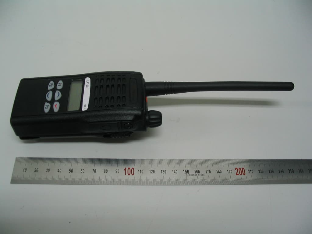
R72EP100
Nov 06, 2007FM Handheld Transceiver (VHF)
Equipment Class
TNF - Licensed Non-Broadcast Transmitter Held to Face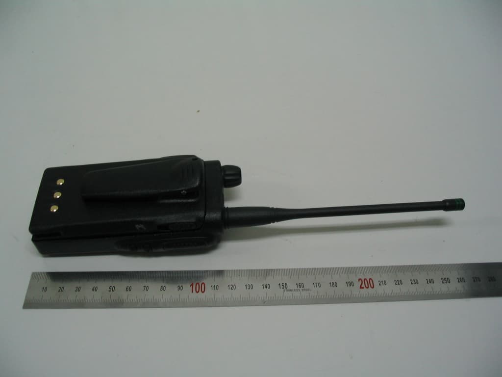
R72EP400
Nov 06, 2007FM Handheld Transceiver (UHF)
Equipment Class
TNF - Licensed Non-Broadcast Transmitter Held to Face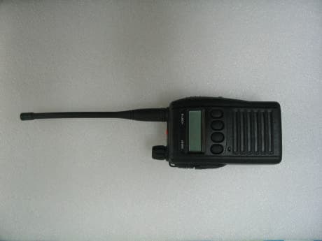
R72IS400
Dec 20, 2005FM Handheld Transceiver
Equipment Class
TNF - Licensed Non-Broadcast Transmitter Held to Face
R72IS100
Dec 20, 2005FM Handheld Transceiver
Equipment Class
TNF - Licensed Non-Broadcast Transmitter Held to Face
R72IP100
Sep 06, 2004FM Handheld Transceiver
Equipment Class
TNF - Licensed Non-Broadcast Transmitter Held to Face