R74TC1688PTwo Way Radio
Shenzhen HYT Science &Technology Co Ltd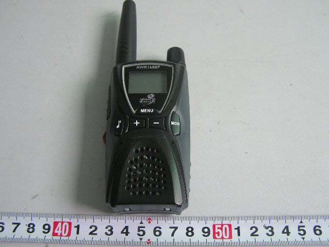
Click to zoom
Application Details
- Equipment Class
- TNF - Licensed Non-Broadcast Transmitter Held to Face
- Date of Grant
- May 24, 2006
- Application Purpose
- Original Equipment
- Date of Application
- May 24, 2006
- Equipment Note
- Two Way Radio
- Frequency Range
- 460.00000000 - 470.00000000
- Country
- China
Documents & Files
Document Text
Text extracted from the exhibit documents filed with the FCC. Open a document above to read the original.
Users Manual
1 Forward Manual Scope This manual is intended for use by experienced technicians familiar with similar types of communication equipment. It contains all service information required for the equipment and is current as of the publication date. 2 Product Safety and RF Exposure for Portable Two-Way Radios Compliance with RF Energy Exposure Standards NOTICE: This radio is intended for use in occupational/controlled applications where users have been made aware of the potential for exposure and can exercise control over their exposure. This radio device is NOT authorized for general population, consumer or similar use. BEFORE USING THIS RADIO, READ THE TRAINING MATERIAL BELOW WHICH CONTAINS IMPORTANT OPERATING INSTRUCTIONS FOR SAFE USAGE AND RF ENERGY AWARENESS AND CONTROL INFORMATION FOR COMPLIANCE WITH RF ENERGY EXPOSURE LIMITS IN APPLICABLE NATIONAL AND INTERNATIONAL STANDARDS. Federal Communication Commission (FCC) Regulations The FCC has established limits for safe exposure to radio frequency (RF) emissions from portable two-way radios. The FCC requires manufacturers to demonstrate compliance with RF exposure limits before portable two-way radios can be marketed in the U.S. When two-way radios are approved for occupational/controlled environment exposure limits, the FCC requires users to be fully aware of, and exercise control over, their exposure. Awareness and control of RF exposure can be accomplished by the use of labels, or by education and training through appropriate means, such as information and instructions in user manuals or safety booklets. Your HYT two-way radio has an RF exposure information label in the battery compartment. The training material below includes useful information about RF exposure and helpful instructions on how to control your RF exposure. Your HYT two-way radio is designed and tested to comply with a number of national and international standards and guidelines (listed below) regarding human exposure to RF electromagnetic energy. In terms of measuring RF energy for compliance with FCC exposure guidelines, your radio radiates measurable RF energy only while it is transmitting (during talking), not when it is receiving (listening) or in standby mode. Compliance and Control Guidelines and Operating Instructions for Portable Two-Way Radios To control your exposure and ensure compliance with the occupational/controlled environment exposure limits, always adhere to the following procedures: * Transmit no more than 50% of the time. To transmit (talk), push the Push-To-Talk (PTT) button. To receive calls, release the PTT button. Transmitting 50% of the time or less is 3 important since the radio generates measurable RF energy exposure only when transmitting (in terms of measuring standards compliance). * Hold the radio in a vertical position in front of the face with the microphone positioned at least one inch (2.5 cm) away from the lips. Keeping the radio at the proper distance is important since RF exposure decreases with increasing distance from the antenna. * For body-worn operation, always use the radio with the HYT Belt-Clip. HYT-approved accessories, antennas, and device combinations have been tested and comply with the occupational/controlled environment RF exposure limits. The use of non–HYT approved accessories may result in exposure levels that may exceed the RF exposure limits for the occupational/controlled environment. * If you are not using a body-worn accessory and are not using the radio held in front of the face, ensure the radio is kept a minimum of 0.7 cm from the body when transmitting. Keeping the radio at a proper distance is important since RF exposure decreases with increasing distance from the antenna. FCC license Information Your HYT radio operates on communications frequencies which are subject to FCC (Federal Communications Commission) Rules & Regulations. FCC Rules require that all operators using Private Land Mobile radio frequencies obtain a radio license before operating their equipment. Application for license must be made on FCC form 601, and schedules D, E, and G. FAX: Forms can be obtained by fax from the FCC Fax-On-Demand system. Call 1-202-418-0177 from your fax machine and request document number 000600 for the form, schedules, and instructions. MAIL: Forms can be ordered by telephone, and will be sent to you by first class mail. Call the FCC Forms Hotline at 1-800-418-FORM (1-800-418-3676). INTERNET: Form 601 and instructions can be downloaded from the FCC Forms website at: http://www.fcc.gov/Forms/Form601/601.html Before filling out your Form 601 application Technical Data section, you must decide which frequency (or frequencies) you will operate on. Refer to the frequency chart on page 16. Questions? Call the FCC for license application questions at 1-888-CALL-FCC (1-888-225-5322). 4 Notices to The User This device complies with Part 15 of the FCC Rules. Operation is subject to the following two conditions: (1) this device may not cause harmful interference, and (2) this device must accept any interference received, including interference that may cause undesired operation. One or more of the following statements may be applicable: FCC WARNING This equipment generates or uses radio frequency energy. Changes or modifications to this equipment may cause harmful interference unless the modifications are expressly approved in the instruction manual. The user could lose the authority to operate this equipment if an unauthorized change or modification is made. 5 SAFETY INFORMATION: Your HYT portable two-way radio has been designed using a low power transmitter. When the PTT switch is pressed, the radio generates radio frequency (RF) electromagnetic energy (EME). This radio is designed to comply with the FCC Report and Order FCC 96-326 (August, 1996). User Safety Information The following precautions are recommended for personnel safety: z DO NOT transmit until all RF connectors are verified secure and any open connectors are …
Text truncated - open the document above for the full version.
External Photos
EXHIBIT B - EUT PHOTOGRAPHS EUT – Front View EUT – Rear View
ID Label/Location Info
EXHIBIT A - FCC ID LABELING AND LOCATION Proposed FCC ID Labeling Proposed FCC ID Location FCC ID Label Location ATTENTION! Restricted to occupational use to satisfy FCC RF exposure limits. See users manual for operating requirements. FCC ID: R74TC-1688P Model: TC-1688P
Operational Description
Specifications Frequency Range 460MHz-470MHz Number of Channels 56 (Max.) Number of CTCSS 38 Number of CDCSS 83 Frequency Error ≤±2.5PPM Radiated Power 0.2 W Transmitter Spurious Emission ≤20uW Modulation Limiting ±2.5KHz Bandwidth ≤8.5KHz Adjacent Channel Power Rejection ≥60dB Modulation AF Distortion ≤10% Receiving Sensitivity ≤0.3uV (12dB SINAD) Co-channel Rejection ≥-8dB Blocking ≥85dB Intermodulation Rejection ≥50dB Adjacent Channel Selectivity ≥50dB Receiver Spurious Emission ≤2nW Receiving AF Distortion ≤10%
Parts List/Tune Up Info
Adjustment Description Before the adjustment, please beforehand save the user’s setting. Required Test Instrument 1. Stabilized power supply 1set 1) The supply voltage can be changed between 2V and 6V DC, and the output current is 2A or more; 2) The standard output voltage is 3.6V DC; 3) The power supply output voltage stabilizes. 2. Ammeter 1 set 3. Digital Voltmeter 1 set 4. Radio Communication Test Set 1 set Test and Adjustment 1. Setting: Put the main unit under test on the jig (Note: Make sure the test terminal and the jig connect well), and turn on the power. 2. VCO Enable “Default Set Mode” function in programming software. And then press “+”, “-” and “MENU” keys simultaneously to turn on the radio and enter adjustment mode. Measurement Adjustment Item Condition Te s t Instrument Terminal PartsMethod Specification/ Remarks Transmit VCO lock voltage CH1: Transmitting Digital Voltmeter P6 L22 Adjust L22 using ceramic screwdriver until the lock voltage reaches the selected range 2.5±0.1V Receive VCO lock voltage CH1: Receiving Digital Voltmeter P6 L22Check Around 1.0V 3. Receiver Measurement Adjustment Item Condition Test InstrumentTerminalParts Method Specification/Remarks RX IF demodulation output Adjust to CH1. Press MON for 1 second to receive. Radio Communication Test Set SSG: -60dB MOD: 1KHz, DEV: 1.5KHz FILTER: 0.3~3KHz Antenna Mic jack L20 Adjust L20 using ceramic screwdriver until the max. AF output signal appears. When adjusting, rotate the volume control to the right position so that the output won’t limit. Measurement Adjustment Item Condition Te s t Instrument Terminal PartsMethod Specification/Remarks Receiving Sensitivity Adjust to CH1. Press MON for 1 second to receive. Radio Communication Te s t S e t SSG: -119dBm, MOD:1KHz DEV: 1.5KHz FILTER: 0.3~3KHz Antenna Mic jack Check SINAD: 12dB or higher Adjust to CH1 and set SQ as level 1 Radio Communication Test Set SSG: -119dBm, Squelch level: -122±1.5dB Squelch Adjust to CH1 and set SQ as level 4 Radio Communication Te s t S e t SSG: -110dBm, Antenna Mic jack Reduce the SSG output signal gradually until AF output mutes. Squelch level: -114±1.5dB 4. Transmitter (Be sure to connect the antenna or dummy load before adjustment) Measurement Adjustment Item Condition Test Instrument TerminalsPartsMethod Specification/Remarks ±2.5ppm Transmitting Frequency Radio Communication Te s t S e t VC1 Use ceramic screwdriver to adjust VC1 so that the center frequency is no more than the error. Transmitting power Adjust to CH1. Press PTT to transmit. Radio Communication Test Set Ammeter Antenna Check ≥700mW Max frequency deviation Adjust to CH1. Press PTT to transmit . Radio Communication Test Set LPF: 15KHz AF OUT: 1KHz/150mV Antenna Mic Jack R77 Use screwdriver to adjust R77 so that frequency deviation is in the regulated range. Frequency deviation: 2.1KHz~2.2KHz Modulation Sensitivity Adjust to CH1. Press PTT to Radio Communication Antenna Mic Jack Check Frequency deviation: 1.1KHz~1.8KHz transmit. Te s t S e t BPF:0.3~3KHz AF OUT: 1KHz/12mV Adjust to CH2 and CTCSS code automatically turns to “1”. Press PTT to transmit. Radio Communication Te s t S e t LPF:0.3KHz Antenna Use screwdriver to adjust R153 and R152 so that CTC frequency deviation is in the regulated range. Frequency deviation: 0.45±0.05KHz Adjust to CH3 and CTCSS code automatically turns to “38”. Press PTT to transmit. Radio Communication Te s t S e t LPF:0.3KHz Antenna Check Frequency deviation: 0.45±0.05KHz CTCSS /CDCSS Frequency Deviation Adjust to CH4; automatically turn to CDCSS. Press PTT to transmit. Radio Communication Te s t S e t LPF:0.3KHz Antenna Check Frequency deviation: 0.5±0.1KHz Set the battery as A Adjust power supply output voltage and check alert level 3.3±0.1V Low Battery Alert Level Set the battery as n Digital Voltmeter Power supply port Power supply Adjust power supply output voltage and check alert level 3.1±0.1V Set the battery as A Adjust power supply output voltage and check power off level 3.1±0.1V Low Battery Power-off Level Set the battery as n Digital Voltmeter Power supply port Power supply Adjust power supply output voltage and check power off level 3.0±0.1V 5. After adjustment, recover the original setting (before adjustment) of the radio through programming software.
Test Setup Photos
EXHIBIT D - TEST SETUP PHOTOGRAPHS Radiated Emission - Front View (Below 1000 MHz) Radiated Emission - Rear View (Below 1000 MHz) Radiated Emission - Front View (Above 1000 MHz) Radiated Emission - Rear View (Above 1000 MHz) Frequency Stability
Contact Information
Applicant
Xiong Lei
Test Firm
Bay Area Compliance Laboratory Corp. (Shenzhen)John Chan
Technical Specifications
| # | Rule Parts | Frequency Range | Power Output | Emission | Tolerance |
|---|---|---|---|---|---|
| 1 | 90 | 460 MHz - 470 MHz | 179.00 mW | 11K0F3E | 2.5000000000 ppm |
Other Applications from Shenzhen HYT Science &Technology Co Ltd

R74TR-800U1
Feb 26, 2008REPEATER (BASE STATION)
Equipment Class
TNB - Licensed Non-Broadcast Station Transmitter
R74TR-800U2
Feb 24, 2008REPEATER BASE STATION
Equipment Class
TNF - Licensed Non-Broadcast Transmitter Held to Face
R74TR-800V
Feb 20, 2008REPEATER (BASE STATION)
Equipment Class
TNB - Licensed Non-Broadcast Station Transmitter
R74TC-620V2
Feb 18, 2008Two-Way Radio
Equipment Class
TNF - Licensed Non-Broadcast Transmitter Held to Face
R74TC-980U1
Jan 14, 2008TWO-WAY RADIO
Equipment Class
TNF - Licensed Non-Broadcast Transmitter Held to Face