R74TC3000Walkie Talkie
Shenzhen HYT Science &Technology Co Ltd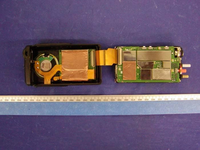
Click to zoom
Application Details
- Equipment Class
- TNF - Licensed Non-Broadcast Transmitter Held to Face
- Date of Grant
- Jul 09, 2004
- Application Purpose
- Original Equipment
- Date of Application
- Jul 09, 2004
- Equipment Note
- Walkie Talkie
- Frequency Range
- 440.00000000 - 470.00000000
- Country
- China
Documents & Files
Document Text
Text extracted from the exhibit documents filed with the FCC. Open a document above to read the original.
Users Manual
1 THANK YOU! We are grateful for your purchase of HYT product. We believe this easy–to-use radio will provide you with dependable and reliable communications. This HYT portable two-way radio is a precision device. Treat it with care, and you will enjoy years of reliable operation. MODELS COVERED IN THIS MANUAL TC3000 VHF Radio TC3000 UHF Radio 2 Contents User Safety, Training, and General Information Compliance with RF Energy Exposure Standards FCC Compliance Precautions Product Inspection Battery Information Accessory Installation Battery Antenna Belt Clip Earplug Cover External Earphone/Microphone (optional) Getting Started Features and Operation Turn on/off the radio Adjust the Volume Select Channel Transmit Receive Monitor Repeater/Talk Around Repeater/ Reverse Frequency Selectable Power Scan Call Selective Call Emergency Siren VOX Feature Built-in Modem Patrol Record Low Battery Alert Troubleshooting Guide Care and Cleaning Optional Accessories Frequency Chart 3 User Safety, Training, and General Information READ THIS IMPORTANT INFORMATION ON SAFE AND EFFICIENT OPERATION BEFORE USING YOUR HYT PORTABLE TWO-WAY RADIO. Compliance with RF Energy Exposure Standards Yo u r HYT two-way radio is designed and tested to comply with a number of national and international standards and guidelines (listed below) regarding human exposure to radio frequency electromagnetic energy. This radio complies with the IEEE (FCC) and ICNIRP exposure limits for occupational/controlled RF exposure environment at duty cycles of up to 50% talk-50% listen and should be used for occupational use only. In terms of measuring RF energy for compliance with the FCC exposure guidelines, your radio radiates measurable RF energy only while it is transmitting (during talking), not when it is receiving (listening) or in standby mode. Note: The approved batteries supplied with this radio are rated for a 5-5-90 duty cycle (5% talk-5% listen-90% standby), even though this radio complies with the FCC occupational RF exposure limits at duty cycles of up to 50% talk. Your HYT two-way radio complies with the following of R F e n e r g y exposure standards and guidelines: z United States Federal Communications Commission, Code of Federal Regulations; 47CFR part 2 sub-part J z American National Standards Institute (ANSI)/Institute of Electrical and Electronic Engineers (IEEE) C95. 1-1992 z Institute of Electrical and Electronic Engineers (IEEE) C95. 1-1999 Edition z International Commission on Non-Ionizing Radiation Protection (ICNIRP) 1998 Operational Instructions and Training Guidelines To ensure optimal performance and compliance with the occupational/controlled environment RF energy exposure limits in the above standards and guidelines, users should transmit no more than 50% of the time and always adhere to the following procedures: Transmit and Receive To transmit (talk), push the Push-To-Talk (PTT) button; to receive, release the PTT button. Hand-held radio operation Hold the radio in a vertical position with the microphone one to two inches (2.5 to 5 cm) away from the lips. Body-worn operation z Always place the radio in an HYT approved clip, holder, holster, case, or body harness for this product. Use of non-HYT-approved accessories may exceed FCC RF exposure guidelines. Antennas & Batteries z Use only HYT approved, supplied antenna or HYT approved replacement antenna. Unauthorized antennas, modifications, or attachments could damage the radio and may violate FCC regulations. 4 z Use only HYT approved, supplied batteries or HYT approved replacement batteries. Use of non- HYT -approved batteries may exceed FCC RF exposure guidelines. Approved Accessories For a list of HYT approved accessories, see the accessories page of this user manual or visit the following website which lists approved accessories: http://www.HYT.com.cn FCC Compliance This equipment has been tested and found to comply with the limits for a Class B digital device, pursuant to part 15 of the FCC Rules. These limits are designed to provide reasonable protection against harmful interference in a residential installation. This equipment generates, uses and can radiate radio frequency energy and, if not installed and used in accordance with the instructions, may cause harmful interference to radio communications. However, there is no guarantee that interference will not occur in a particular installation. If this equipment does cause harmful interference to radio or television reception, which can be determined by turning the equipment off and on, the user is encouraged to try to correct the interference by one or more of the following measures: Reorient or relocate the receiving antenna. Increase the separation between the equipment and receiver. Connect the equipment into an outlet on a circuit different from that to which the receiver is connected. Consult the dealer or an experienced radio/TV technician for help. FCC Requirements Your radio must be properly licensed Federal Communications Commission prior to use. Your HYT Wireless dealer can assist you in meeting these requirements. Your dealer will program each radio with your authorized frequencies, signaling codes, etc., and will be there to meet your communications needs as your system expands. Precautions • Only qualified technicians are allowed to maintain this product. • Do not use the radio or charge a battery in explosive areas such as coal gas, dust, steam, etc. • Switch OFF the radio while refueling or parking at gas station. • Do not modify or adjust this radio without permission. • Do not expose the radio to direct sunlight over a long time, nor place it close to heating source. • Do not place the radio in excessively dusty, humid areas, nor on unstable surfaces. Safety: It is important that the operator is aware of and understands hazards common to the operation of any radio. 5 Product Inspection Thank you for your use of HYT portable two-way radio TC3000. Before use, you are recomme…
Text truncated - open the document above for the full version.
External Photos
Shenzhen HYT Science&Technology Co.,Ltd FCC ID: R74TC3000 APPENDIX C - EUT PHOTOGRAPHS EUT – Front View EUT – Rear View Shenzhen HYT Science&Technology Co.,Ltd FCC ID: R74TC3000 EUT – Top View Antenna View Shenzhen HYT Science&Technology Co.,Ltd FCC ID: R74TC3000 EUT – Board and Housing View Charger View Shenzhen HYT Science&Technology Co.,Ltd FCC ID: R74TC3000 Adapter View
ID Label/Location Info
APPENDIX A - FCC ID LABELING AND LOCATION Proposed FCC ID Labeling Proposed RF Safety Labeling Proposed FCC ID Location FCC ID: R74TC3000 This device must be restricted to occupational use to satisfy FCC RF exposure compliance. See owner’s manual for specific operating instruction. This device must be restricted to occupational use to satisfy FCC RF exposure compliance. See owner's manual for specific operating instruction.
Parts List/Tune Up Info
Adjustment Description Required Test Instrument Radio communication test set 1 set Scanner 1 set 3A/10V power supply 1 set Digital voltmeter 1 set 3A Ammeter 1 set Preparation Open the programming software in PC and operate as the following instructions. 1. Programme Download: Connect the radio with the computer via programming cable. And then turn the power on. LED glows red. Click “Programme” → “Download” on the interface to choose programme. Click “Open” to begin download and LED flashes red. When download is complete, click “End” and turn the power off. And then disconnect the programming cable. 2. Initialization: Turn the power on while holding down [PTT] and [A] key simultaneously. LED glows orange and a BEEP sounds. Radio channel frequency and setting data are initialized. 3. Destination Set: Connect the radio with the computer via programming cable. And then turn the power on. LED glows red. Set “frequency range” on the programming software interface. And then click “Programme” → “ Writing”. 4. Factory Setting The compander is open. Squelch level 2. Adjustment mode is disabled. Adjustment VCO Measurement Adjustment Item Condition Test Instrument Terminal Part Method Specification/ Remarks 1. Setting Power supply 7.5V 1.Turn to CH1. Press PTT. TX High Check 3.3V±0.2V 2.Transmit VCO lock voltage 2. Press PTT again. TX Low Check 1.0V±0.4V 1. Turn to CH2. Press PTT. TX High Check 3.1V±0.2V 3. Receiving VCO lock voltage 2. Press PTT again. TX Low Digital Voltmeter CV TC350 TC351 Check 1.0V±0.4V Transmitter Measurement Adjustment Item Condition Test InstrumentTerminal Part Method Specification /Remarks 1. Transmit f Turn to CH3. Radio Citi ANT [B] (up) [C] (d) Adjust to center fP Error≤150Hz frequency Press PTT. Communication Test Set (down) frequency. Press [A] to save. 1. Turn to CH4. Press PTT. Center frequency Adjust to 4.0 W, I≤1.6A. Press [A] to save. 2. Press PTT. Frequency changes to low frequency. Adjust to 4.0 W, I≤1.6A. Press [A] to save. High 3. Press PTT again. Frequency changes to high frequency. Adjust to 4.0 W, I≤1.6A. Press [A] to save. 4.0W±0.3W 4.0W±0.3W 1. Turn to CH5. Press PTT. Center frequency. Adjust to 1.0 W, I≤0.7A. Press [A] to save. 2. Press PTT. Frequency changes to low frequency. Adjust to 1.0 W, I≤0.7A. Press [A] to save. 2. Power Low 3. Press PTT again. Frequency changes to high frequency. Radio Communication Test Set Ammeter ANT [B] (up) [C] (down) Adjust to 1.0 W, I≤0.7A. Press [A] to save. 1W±0.3W 1. Turn to CH6. Press PTT. The radio operates with wideband. Center frequency. 2. Press PTT. Frequency changes to low frequency. 3. Press PTT again. Frequency changes to high frequency. 3. CDCSS balance Wideba- nd Narrow- band 4. Press [A] for two seconds. LED flashes indicating that the radio operates with narrowband. Center frequency. Adjust narrowband following the above steps. Radio Communication Test Set LPF: 15KHz ANT [B] (up) [C] (down) Rectify the waveform to square wave. Press [A] to save. Wideba- nd 1. Turn to CH7. Press PTT. The radio operates with wideband. Center frequency. Adjust it to 4.0KHz±100Hz. Press [A] to save. 4. Maximu- m frequenc -y deviaion Narrow- band 2. Press [A] for two seconds. LED flashes indicating that the radio operates with narrowband. Center frequency. Radio Communication Test Set LPF: 15KHz AF: 1KHz 1V ANT MIC Jack [B] (up) [C] (down) Adjust it to 2.0KHz±100Hz. Press [A] to save. 5. MIC Sensitivity Turn to CH8. Press PTT. The radio operates with wideband. Center frequency. Radio Communication Test Set LPF: 15KHz AF: 1KHz 24mV ANT MIC Jack [B] (up) [C] (down) Check frequency deviation 2.9±0.1KHz. Press [A] to save. Adjust as wideband. 1. Turn to CH9. Press PTT. The radio operates with wideband. Center frequency. 2. Press PTT. Frequency changes to low frequency. Wideba- nd 3. Press PTT again, frequency changes to high frequency. Adjust deviation to 0.70KHz±50Hz. Press [A] to save. 4. Press [A] for two seconds. LED flashes indicating that the radio operates with narrowband. High frequency. 5. Press PTT. Frequency changes to center frequency. 6. CTCSS deviation Narrow- band 6. Press PTT. Frequency changes to low frequency. Radio Communication Test Set LPF: 3KHz ANT [B] (up) [C] (down) Adjust deviation to 0.35KHz±50Hz. Press [A] to save. Wideba- nd Turn to CH10. See CTCSS deviation adjustment. Adjust deviation to 0.70KHz±50Hz. Press [A] to save. 7. CDCSS deviation Narrowb -and See CTCSS deviation adjustment. Radio Communication Test Set LPF: 3KHz ANT [B] (up) [C] (down) Adjust deviation to 0.35KHz±50Hz. Press [A] to save. Wideba- nd Turn to CH11. See CTCSS deviation adjustment. Adjust deviation to 3KHz±0.1KHz. Press [A] to save. 8.FFSK deviation Narrow- band See CTCSS deviation adjustment. Radio Communication Test Set LPF: 3KHz ANT [B] (up) [C] (down) Adjust deviation to 1.45KHz±0.05KH z Press [A] to save. 9.TONE deviation Wideba- nd Turn to CH12. See CTCSS deviation adjustment. Radio Communication Test Set LPF: 3KHz ANT [B] (up) [C] (down) Adjust it to 3KHz±0.1KHz. Press [A] to save. Narrow- band See CTCSS deviation adjustment. Adjust it to 1.45KHz±0.05KH z Press [A] to save. 10. Low battery alert level Turn to CH15. Adjust voltage to 6.2V. Digital Voltmeter Press [A] to save. 11.VOX Sensitivity Turn to CH16. Radio Communication Test Set LPF:15KHz AF:1KHz 3mV ANT MIC Jack Press [A] to save. Receiver Measurement Adjustment Item Condition Test InstrumentTerminal Part Method Specification /Remarks 1. Turn to CH13. Press PTT. Center frequency. 2. Press PTT. Frequency changes to low frequency. Sensitivity 3. Press PTT. Frequency changes to high frequency. Scanner ANT T1 [B] (up) [C] (down) Adjust the waveform. Press [A] to save. 1. Turn to CH14. Press PTT. The radio operates with wideband. Center frequency. 2. Press PTT. Frequency changes to low frequency. Wideba- nd 3. Press PTT. Frequency changes to high frequency. Radio Communication Test Set SSG output: - 118dBm MOD: 1KHz DEV: ±3KHz FILTER: 0.3- 3.4KHz Adjust radio communicati…
Text truncated - open the document above for the full version.
RF Exposure Info
Note: This test report is specially limited to the above client company and the product model only. It may not be duplicated without prior written consent of Bay Area Compliance Laboratory Corporation. This report must not be used by the client to claim product endorsement by NVLAP or any agency of the U.S. Government. SAR EVALUATION REPORT For SHENZHEN HYT SCIENCE&TECHNOLOGY CO.,LTD R2-High-Tech Industrial Park ShenZhen, China FCC ID: R74TC3000 This Report Concerns: Original Report Equipment Type: Two-way Radio Test Engineer: Daniel Deng / Report No.: R0406283S Report Date: 2004-07-01 Reviewed By: Ling Zhang / Prepared By: Bay Area Compliance Laboratory Corporation 230 Commercial Street Sunnyvale, CA 94085 Tel: (408) 732-9162 Fax: (408) 732 9164 SHENZHEN HYT SCIENCE&TECHNOLOGY CO.,LTD FCC ID: R74TC3000 Report #R0406283S SAR Evaluation Report Page 2 of 51 TABLE OF CONTENTS SUMMARY....................................................................................................................................................................3 1 - REFERENCE ...........................................................................................................................................................4 2 - TESTING EQUIPMENT.........................................................................................................................................5 2.2 EQUIPMENT CALIBRATION CERTIFICATE...............................................................................................................5 2.3 DIPOLE CALIBRATION..........................................................................................................................................15 3 - EUT DESCRIPTION .............................................................................................................................................22 4 - SYSTEM TEST CONFIGURATION...................................................................................................................23 4.1 JUSTIFICATION.....................................................................................................................................................23 4.2 EUT EXERCISE PROCEDURE................................................................................................................................23 4.3 EQUIPMENT MODIFICATIONS...............................................................................................................................23 5 – CONDUCTED OUTPUT POWER ......................................................................................................................24 5.1 PROVISION APPLICABLE.......................................................................................................................................24 5.2 TEST PROCEDURE................................................................................................................................................24 5.3 TEST EQUIPMENT.................................................................................................................................................24 5.4 TEST RESULTS.....................................................................................................................................................24 6 - DOSIMETRIC ASSESSMENT SETUP...............................................................................................................25 6.1 MEASUREMENT SYSTEM DIAGRAM.....................................................................................................................26 6.2. SYSTEM COMPONENTS........................................................................................................................................27 6.3 MEASUREMENT UNCERTAINTY............................................................................................................................31 7 - SYSTEM EVALUATION .....................................................................................................................................32 7.1 SIMULATED TISSUE LIQUID PARAMETER CONFIRMATION...................................................................................32 7.2 EVALUATION PROCEDURES..................................................................................................................................32 7.3 SYSTEM ACCURACY VERIFICATION.....................................................................................................................33 7.4 SAR EVALUATION PROCEDURE...........................................................................................................................36 7.5 EXPOSURE LIMITS................................................................................................................................................37 8 - TEST RESULTS ....................................................................................................................................................38 8.1 SAR TEST DATA..................................................................................................................................................38 8.2 PLOTS OF TEST RESULT.......................................................................................................................................38 EXHIBIT A - SAR SETUP PHOTOGRAPHS .........................................................................................................41 BODY-WORN WITH BELT CLIP & HEADSET IN TOUCHING WITH PHANTOM...............................................................41 2.5CM SEPARATION TO FLAT PHANTOM.....................................................................................................................41 EXHIBIT B - EUT PHOTOGRAPHS .......................................................................................................................42 EUT – FRONT VIEW...............................................................................…
Text truncated - open the document above for the full version.
Test Report
Note: The test report is specially limited to the above company and the product model only. It may not be duplicated without prior written consent of Bay Area Compliance Laboratory Corporation. This report must not be used by the client to claim product certification, approval, or endorsement by NVLAP, NIST or any agency of the US Government. FCC PART 90 TYPE APPROVAL EMI MEASUREMENT AND TEST REPORT For SHENZHEN HYT SCIENCE&TECHNOLOGY CO.,LTD R2-High-Tech Industrial Park ShenZhen, China FCC ID: R74TC3000 This Report Concerns: Original Report Equipment Type: Two-way Radio Test Engineer: Benjamin Jin Report No.: R0405064 Report Date: 2004-06-02 Reviewed By: Ling Zhang Prepared By: Bay Area Compliance Laboratory Corporation 230 Commercial Street Sunnyvale, CA 94085 Tel: (408) 732-9162 Fax: (408) 732 9164 Shenzhen HYT Science&Technology Co.,Ltd FCC ID: R74TC3000 Report # R0405064Rpt.doc Page 2 of 26 FCC Part 90 Type Approval Report TABLE OF CONTENTS GENERAL INFORMATION.......................................................................................................................................4 PRODUCT DESCRIPTION FOR EQUIPMENT UNDER TEST (EUT) ....................................................................................4 OBJECTIVE...................................................................................................................................................................4 RELATED SUBMITTAL(S)/GRANT(S).............................................................................................................................4 TEST METHODOLOGY..................................................................................................................................................4 TEST FACILITY.............................................................................................................................................................5 SYSTEM TEST CONFIGURATION ..........................................................................................................................6 JUSTIFICATION.............................................................................................................................................................6 BLOCK DIAGRAM.........................................................................................................................................................6 EQUIPMENT MODIFICATIONS.......................................................................................................................................6 TEST SETUP BLOCK DIAGRAM.....................................................................................................................................6 SUMMARY OF TEST RESULTS ...............................................................................................................................7 §2.1046 – CONDUCTED OUTPUT POWER .............................................................................................................8 PROVISION APPLICABLE...............................................................................................................................................8 TEST PROCEDURE........................................................................................................................................................8 TEST EQUIPMENT.........................................................................................................................................................8 ENVIRONMENTAL CONDITIONS....................................................................................................................................8 TEST RESULTS.............................................................................................................................................................8 §2.1046 AND §90.205 – RF OUTPUT POWER..........................................................................................................9 PROVISION APPLICABLE...............................................................................................................................................9 TEST PROCEDURE........................................................................................................................................................9 TEST EQUIPMENT LIST AND DETAILS.........................................................................................................................10 ENVIRONMENTAL CONDITIONS..................................................................................................................................10 TEST RESULTS...........................................................................................................................................................10 §2.1047, §90.207 - MODULATION CHARACTERISTIC ......................................................................................11 APPLICABLE STANDARD............................................................................................................................................11 TEST PROCEDURE......................................................................................................................................................11 TEST EQUIPMENT.......................................................................................................................................................11 ENVIRONMENTAL CONDITIONS..................................................................................................................................11 TEST RESULTS...........................................................................................................................................................11 §2.1049, AND § 90.209 – OCCUPIED BANDWIDTH .............................................................................................14 APPLICABLE STANDARD....................................................................…
Text truncated - open the document above for the full version.
Contact Information
Applicant
Xiong Lei
Test Firm
Bay Area Compliance LaboratoryJohn Chan
Technical Specifications
| # | Rule Parts | Frequency Range | Power Output | Emission | Tolerance |
|---|---|---|---|---|---|
| 2 | 9 | 440 MHz - 470 MHz | 4.786 W | 11K0F3E | 2.5 ppm |
Other Applications from Shenzhen HYT Science &Technology Co Ltd

R74TR-800U1
Feb 26, 2008REPEATER (BASE STATION)
Equipment Class
TNB - Licensed Non-Broadcast Station Transmitter
R74TR-800U2
Feb 24, 2008REPEATER BASE STATION
Equipment Class
TNF - Licensed Non-Broadcast Transmitter Held to Face
R74TR-800V
Feb 20, 2008REPEATER (BASE STATION)
Equipment Class
TNB - Licensed Non-Broadcast Station Transmitter
R74TC-620V2
Feb 18, 2008Two-Way Radio
Equipment Class
TNF - Licensed Non-Broadcast Transmitter Held to Face
R74TC-980U1
Jan 14, 2008TWO-WAY RADIO
Equipment Class
TNF - Licensed Non-Broadcast Transmitter Held to Face