R74TC3000VTwo-Way Radio
Shenzhen HYT Science &Technology Co Ltd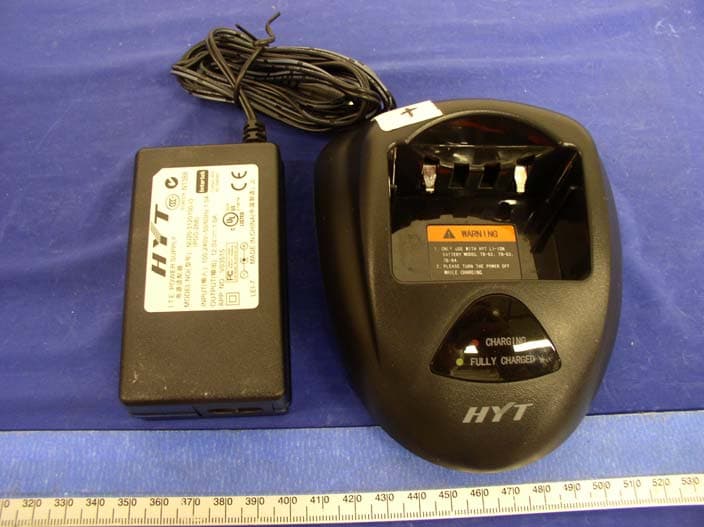
Click to zoom
Application Details
- Equipment Class
- TNF - Licensed Non-Broadcast Transmitter Held to Face
- Date of Grant
- Dec 22, 2004
- Application Purpose
- Original Equipment
- Date of Application
- Nov 07, 2004
- Equipment Note
- Two-Way Radio
- Frequency Range
- 145.00000000 - 175.00000000
- Country
- China
Documents & Files
Document Text
Text extracted from the exhibit documents filed with the FCC. Open a document above to read the original.
Users Manual
1 Content General Brief Introduction Radio Modes Circuit Description CPU Pins Adjustment Description TC3000-U Part List (Control Board) TC3000-U Part List (RF Board) TC3000-V Part List (Control Board) TC3000-V Part List (RF Board) Disassembly and Assembly for Repair Exploded View Part List 2 Packing TC3000-U PC Board View TC3000-V PC Board View TC3000 Block Diagram TC3000-U Schematic Diagram TC3000-V Schematic Diagram Specification 2 General Manual Scope This manual is intended for use by experienced technicians familiar with similar types of communication equipment. It contains all service information required for the equipment and is current as of the publication date. User Safety Information The following precautions are recommended for personnel safety: z DO NOT transmit until all RF connectors are verified secure and any open connectors are properly terminated. z SHUT OFF and do not operate this equipment near electrical blasting caps or in an explosive atmosphere. z When in vehicles with an airbag, do not place a portable radio in the area over an airbag or in the airbag deployment area. z Do not expose the radio to direct sunlight for a long time nor place it close to a heating source. z Do not use any portable radio with a damaged antenna. If a damaged antenna comes into contact with your skin, a minor burn may result. z When transmitting with a portable radio, hold the radio in a vertical position with its microphone about 5 centimeters away from your mouth. z If you wear a portable radio on your body, be sure to keep the antenna at least 2.5 centimeters away from your head or body when transmitting. z This equipment should be serviced by a qualified technician only. 3 Brief Introduction (1) Antenna Used to transmit/receive signals. (2) LED Following table indicates LED indication and corresponding radio status. LED Status No display Standby Green Receive Red Transmit Flashing green Scan Flashing red Low battery voltage Flashing orange Call waiting (3) Channel Selector Used to select wanted channel. (4) Programmable key [A] (5) Power/Volume Control Knob Rotate the Power/Volume Knob clockwise until a “click” is heard to turn the radio on, fully counter clockwise to turn the radio off. When the radio is on, turn the knob to adjust volume. (6) Battery Latch Used to fasten the battery. (7) Speaker Used to output sounds. (8) Microphone Used to input sounds. (9) External Jack Used to connect with external earphone or programming cable. (10) Belt Clip Used to clip the radio on your belt. 4 (11) Battery Pack (12) PTT key Press and hold PTT, radio operates in transmit mode. Release PTT, radio returns to receive mode. (13) Programmable Key [B] (14) Programmable Key [C] The following table shows the key function when briefly pressed, pressed and held or held down: Key function Key Function Briefly Press Press and Hold Hold Down Emergency Siren Enable emergency siren Disable emergency siren - Monitor - - Monitor Scan Enable/Disable scan Enable/Disable scan - Nuisance Delete Delete nuisance channel in scan Delete nuisance channel in scan - Select High/Low Power Select High/Low Power Select High/Low Power - Repeater/Talk Around Select Repeater or Talk Around Mode Select Repeater or Talk Around Mode - Repeater/Reverse Frequency Select Repeater or Reverse Frequency Mode Select Repeater or Reverse Frequency Mode - Call Transmit a Call Transmit a Call - Note: Please contact your dealer for more details about programmable keys. 5 Radio Modes Radio Feature Description 1. CTCSS/CDCSS/2-Tone/5-Tone 2. Channel Spacing 25KHz/12.5KHz (Wide/Narrow) 3. Programmable key 4. Squelch Tail Elimination 5. Priority Channel Scan/Nuisance Delete 6. Busy Channel Lockout 7. High/Low Power 8. Emergency Siren 9. Repeater/Talk Around 10. Call 11. TOT 12. VOX 13. Battery Save 14. Low Battery Alert 15. Voice Compression and Expansion 16. Software Upgrade 17. Wired Clone 18. PC Mode Frame of Radio Modes Entry for Mode Startup User Mode Turn the power on to enter user mode. This mode is for normal operation. Clone Mode 1) Connect the two radios with the clone cable. Turn the power on while holding down PTT and programmable key B simultaneously. After two seconds, a BEEP sounds and LED glows orange indicating that the radio enters clone mode. 2) In clone mode, pressing programmable key B can begin wired clone. MCU transmit data Power On User Mode Clone Mode PC Mode Adjustment Mode All Reset Mode 6 directly through UART port. During cloning, LED of source radio flashes red and that of target radio flashes green. A BEEP sounds when cloning is complete. PC Mode 1) Connect the radio with a PC by programming cable. And then turn the power on. The radio enters PC mode after two seconds and LED glows orange. 2) Data can be transferred between MCU and PC via UART port. If data is transferred to the radio from PC, it can be programmed into the EEPROM by MCU and LED flashes red during data transfer. If data is transferred to PC from the radio, MCU sends the EEPROM data to PC and LED flashes green during data transfer. 3) You can update software and provide second development feature for the user via PC update programme. LED flashes orange during programme download. 4) To exit PC mode and enter conventional mode or other mode, turn on the power again. All Reset Mode Turn on the power while holding down PTT and programmable key A simultaneously (or short circuit the two SELF points) to enter all reset mode. The EEPROM data is all reset. A BEEP sounds and LED glows orange when All Reset is complete. Adjustment Mode Turn the power on while holding down PTT and programmable key C, after two seconds, the radio enters adjustment mode. LED glows orange. Rotate channel selector knob to select corresponding test item. Hold down A key to switch between wideband and narrowband. Briefly press A key to save data. Press B key to adjust upwards and C downwards. Press PTT to transmit or switch among center, low and high frequency. CH1-CH16 are define…
Text truncated - open the document above for the full version.
Users Manual
1 THANK YOU! We are grateful for your purchase of HYT product. We believe this easy–to-use radio will provide you with dependable and reliable communications. This HYT portable two-way radio is a precision device. Treat it with care, and you will enjoy years of reliable operation. MODELS COVERED IN THIS MANUAL TC3000 VHF Radio TC3000 UHF Radio 2 Contents User Safety, Training, and General Information Compliance with RF Energy Exposure Standards FCC Compliance Precautions Product Inspection Battery Information Accessory Installation Battery Antenna Belt Clip Earplug Cover External Earphone/Microphone (optional) Getting Started Features and Operation Turn on/off the radio Adjust the Volume Select Channel Transmit Receive Monitor Repeater/Talk Around Repeater/ Reverse Frequency Selectable Power Scan Call Selective Call Emergency Siren VOX Feature Built-in Modem Patrol Record Low Battery Alert Troubleshooting Guide Care and Cleaning Optional Accessories Frequency Chart 3 User Safety, Training, and General Information READ THIS IMPORTANT INFORMATION ON SAFE AND EFFICIENT OPERATION BEFORE USING YOUR HYT PORTABLE TWO-WAY RADIO. Compliance with RF Energy Exposure Standards Yo u r HYT two-way radio is designed and tested to comply with a number of national and international standards and guidelines (listed below) regarding human exposure to radio frequency electromagnetic energy. This radio complies with the IEEE (FCC) and ICNIRP exposure limits for occupational/controlled RF exposure environment at duty cycles of up to 50% talk-50% listen and should be used for occupational use only. In terms of measuring RF energy for compliance with the FCC exposure guidelines, your radio radiates measurable RF energy only while it is transmitting (during talking), not when it is receiving (listening) or in standby mode. Note: The approved batteries supplied with this radio are rated for a 5-5-90 duty cycle (5% talk-5% listen-90% standby), even though this radio complies with the FCC occupational RF exposure limits at duty cycles of up to 50% talk. Your HYT two-way radio complies with the following of R F e n e r g y exposure standards and guidelines: z United States Federal Communications Commission, Code of Federal Regulations; 47CFR part 2 sub-part J (Body 0.00975 mW/g; Head 0.01135 mW/g) z American National Standards Institute (ANSI)/Institute of Electrical and Electronic Engineers (IEEE) C95. 1-1992 z Institute of Electrical and Electronic Engineers (IEEE) C95. 1-1999 Edition z International Commission on Non-Ionizing Radiation Protection (ICNIRP) 1998 Operational Instructions and Training Guidelines To ensure optimal performance and compliance with the occupational/controlled environment RF energy exposure limits in the above standards and guidelines, users should transmit no more than 50% of the time and always adhere to the following procedures: Transmit and Receive To transmit (talk), push the Push-To-Talk (PTT) button; to receive, release the PTT button. Hand-held radio operation Hold the radio in a vertical position with the microphone one to two inches (2.5 to 5 cm) away from the lips. Body-worn operation z Always place the radio in an HYT approved clip, holder, holster, case, or body harness for this product. Use of non-HYT-approved accessories may exceed FCC RF exposure guidelines. z If you do not use an HYT approved body-worn accessory and are not using the radio in the intended use position in front of the face, then ensure the antenna and the radio are kept one inch (2.5 cm) from the body when transmitting. 4 Antennas & Batteries z Use only HYT approved, supplied antenna or HYT approved replacement antenna. Unauthorized antennas, modifications, or attachments could damage the radio and may violate FCC regulations. z Use only HYT approved, supplied batteries or HYT approved replacement batteries. Use of non- HYT -approved batteries may exceed FCC RF exposure guidelines. Approved Accessories For a list of HYT approved accessories, see the accessories page of this user manual or visit the following website which lists approved accessories: http://www.HYT.com.cn FCC Compliance This equipment has been tested and found to comply with the limits for a Class B digital device, pursuant to part 15 of the FCC Rules. These limits are designed to provide reasonable protection against harmful interference in a residential installation. This equipment generates, uses and can radiate radio frequency energy and, if not installed and used in accordance with the instructions, may cause harmful interference to radio communications. However, there is no guarantee that interference will not occur in a particular installation. If this equipment does cause harmful interference to radio or television reception, which can be determined by turning the equipment off and on, the user is encouraged to try to correct the interference by one or more of the following measures: Reorient or relocate the receiving antenna. Increase the separation between the equipment and receiver. Connect the equipment into an outlet on a circuit different from that to which the receiver is connected. Consult the dealer or an experienced radio/TV technician for help. Changes or modifications not expressly approved in writing may cause harmful interference and void the user’s authority to operate this equipment. FCC Requirements Your radio must be properly licensed Federal Communications Commission prior to use. Your HYT Wireless dealer can assist you in meeting these requirements. Your dealer will program each radio with your authorized frequencies, signaling codes, etc., and will be there to meet your communications needs as your system expands. Precautions • Only qualified technicians are allowed to maintain this product. • Do not use the radio or charge a battery in explosive areas such as coal gas, dust, steam, etc. • Switch OFF the radio while refueling or parking at gas station. • Do not modify or adjust this radio without permi…
Text truncated - open the document above for the full version.
External Photos
APPENDIX C - EUT EXTERNAL PHOTOGRAPHS EUT – Front View EUT – Rear View EUT – Battery Removed Back View Antenna View EUT – Top View Battery View Headset Simulator View Charger View
ID Label/Location Info
APPENDIX A - FCC ID LABELING AND LOCATION Proposed FCC ID Labeling Proposed FCC ID Location Battery removed, Rear Side of EUT / Proposed Label Location ATTENTION! Restricted to occupational use to satisfy FCC RF exposure limits. See users manual for operating requirements. FCC ID: R74TC3000V Model: TC3000V
Internal Photos
APPENDIX C - EUT INTERNAL PHOTOGRAPHS Main Board – Component with Shielding View Main Board – Component without Shielding View Main Board – Solder with Shielding View Main Board – Solder without Shielding View Secondary Board – Component View Secondary Board – Solder View
Operational Description
1 Circuit Description 1. Power Supply Power supply of the radio is derived from the battery, which supplies battery B+ after passing through fuse 3A and then feeds through power switch. The power supplies voltage for three AVRs. IC505 supplies 5V (5M) voltage for the control circuit. IC9 supplies 5V (5C) voltage for the shared circuit. And IC6 supplies voltage for the transmit/receive circuit. In transmit mode, 5TC becomes low voltage and Q3 is turned on to supply 5V(5T) voltage for the transmit circuit. In receive mode, 5RC becomes low voltage and Q2 is turned on to supply 5V (5R) voltage for the receive circuit. BATTFUSE PROTECT 5C 5M BUFF 1/2BIA S AVR AVR SW 5R 5T AVR SW SW SAVE 5RC 5TC Fig. 1 Power Supply Block Diagram 2. PLL Frequency Synthesizer PLL circuit generates the first local oscillator signal for reception and RF signal for transmission. CPU Q416 UL X401 IC400 PLL IC500 CV CLK,DAT,EN TCXO VCO BUFFSW MB D100 T/R To Drive Amp BUFF D103 SW To Mixer Q310 Fig2. PLL circuit 1) PLL IC400 is fractional divider. Step frequency of PLL circuit is 2.5KHz or 6.25KHz. A 16.8MHz reference oscillator signal is divided at IC400 by a fixed counter to generate a 20KHz or 50KHz reference frequency. Output signal from VCO is buffer amplified by Q416 and divided at IC400 by a frequency divider. Divided signal is compared in the phase comparator with 20KHz or 50KHz reference signal of IC400. 2 Output signal from phase comparator is filtered through a low pass filter and passed to the VCO to control oscillator frequency. 2) VCO The operating frequency is generated by Q352 in transmit mode and by Q350 in receive mode. Operating frequency generates a control voltage by phase comparator to control varactor diodes so that the oscillator frequency is the same as the MCU preset frequency (D350, D352, D354 and D355 in transmit mode and D351, D353, D356 and D357 in receive mode). T/R pin is set high level in receive mode and low in transmit mode. The output from Q352 and Q350 is amplified by Q354 and sent to buffer amplifier. 3) Unlock Detector An unlock condition appears if low level appears at LOCK pin of IC400. Transmission is forbidden if this condition is detected by microprocessor. 3. Receiver The receiver utilizes double conversion superheterodyne. C ANT ANT SW BPFQ201 RF AMP BPF MCF XF201 IF AMP Q222 MIXER IC218 CF201,202 IF,MIX,DET IC204 AF AMP IC720SP 1st Local OSC (PLL) 2nd Local OSC IF AMP Q216 Fig.3 Receiver Section Configuration 1) Front-end Amplifier The signal from antenna is amplified at RF amplifier (Q201) after passing through a transmit/receive switch circuit and a band pass filter. The amplified signal is filtered through a band pass filter to remove unwanted signals before it passes the first mixer. 2) First Mixer The signal from RF amplifier is mixed with the first local oscillator signal from PLL frequency synthesizer circuit at the first mixer (IC218) to create a 44.85MHz first IF signal. The first IF signal is then fed through a crystal filter (XF201) to further remove spurious signals from adjacent channel. 3) IF Amplifier The first IF signal is amplified by Q216 before passing through crystal filter and by Q222 after crystal filter and then enters IF processing chip IC204. The signal is mixed with the second local oscillator signal again in IC204 to create a 455KHz second IF signal. The second IF signal then passes through a 455KHz ceramic filter (wideband: CF201/narrowband: CF202) to eliminate unwanted signals before it is amplified and detected in IC204. 4) Narrowband/Wideband Switch Circuit Turn on ceramic filter CF201 (wideband)/CF202 (narrowband) to set each channel as 3 wideband or narrowband. W/N pin of IC500 outputs wideband (high level) and narrowband (low level) signal. 5) AF Amplifier The result AF signal from IC204 is amplified by IC606, and then passes through AF processing chip IC601 and compander IC603. The processed AF signal is then amplified by an AF power amplifier (IC720) to drive the speaker. 4. Transmitter 1) AF and Signaling Modulating signal from the microphone passes through Q700 switch and compander IC603 before it enters AF processing chip IC601. Under the control of MCU, IC601 produces DTMF/CTCSS/CDCSS/2-Tone/5-Tone signaling, which then pass through MOD and enter VCO together with the modulating signal for direct FM modulation. (See fig.5) 2) RF Amplifier The transmit signal from VCO buffer amplifier (Q310) is amplified by Q101 and Q102. The amplified signal is then amplified by the power amplifier Q105 and Q107 (include a two-stage FET amplifier) to create 4.0W RF power. (See fig.4) D C B A Title AMP Q101.102 5T DRIVE AMP Q105 FINAL AMP Q107 ANT SW D101LPF ANT ANT SW D201.202 RX Q106 SW Q109 SW 5T IC100 APC DET Q103.Q104 B SW B APC 5T TH101 SW Q110 5T Q108 SW 5TC Fig.4 APC System 3) Antenna Switch and LPF Output signal from RF amplifier passes through a low-pass filter network and a transmit/receive switch circuit comprised of D101, D201 and D202 before it reaches the antenna terminal. D201 and D202 is turned on (conductive) in transmit mode and off (isolated) in receive mode. 4) APC The automatic power control (APC) circuit stabilizes the transmit output power by detecting the drain current of final stage amplifier FET. IC100 (2/2) compares the preset reference voltage with the voltage obtained from final current. APC voltage is proportional to the difference between auto detect voltage and reference voltage 4 output from IC100 (1/2). The output voltage controls FET power amplifier and keeps the transmitter output power constant. The output voltage can be varied by the microprocessor, which hence controls the transmitter output power. 5. Signalling Section The block diagram of signaling section is shown as figure 5. D601 LIMITTER X601 BASEBAND PROCESSOR IC601 BBP_IRQN BBP_RPL SP MIC SW Q700 AF PA IC710 SW Q710 MIC AUDIO_EN EXT_SPK+ EXT_MIC BBP_CSN BBP_CMD BBP_CLK Q701 SW EXT_MIC_SELEXT_SP_SEL IC605 BUFFER Ver Vbias COMPANDER IC603 SW COM_SWEXP EXP…
Text truncated - open the document above for the full version.
RF Exposure Info
Note: The test report is specially limited to the above company and the product model only. It may not be duplicated without prior written consent of Bay Area Compliance Laboratory Corporation. This report must not be used by the client to claim product certification, approval, or endorsement by NVLAP, NIST or any agency of the US Government. SAR EVALUATION REPORT For SHENZHEN HYT SCIENCE&TECHNOLOGY CO.,LTD R2-High-Tech Industrial Park ShenZhen, China FCC ID: R74TC3000V This Report Concerns: Original Report Equipment Type: Transceiver, PTT, Two-way Radio Test Engineer: Eric Hong Report No.: R0408272S Report Date: 2004-10-31 Reviewed By: Daniel Deng Prepared By: Bay Area Compliance Laboratory Corporation 230 Commercial Street Sunnyvale, CA 94085 Tel: (408) 732-9162 Fax: (408) 732 9164 SHENZHEN HYT SCIENCE&TECHNOLOGY CO.,LTD FCC ID: R74TC3000V Report #R0408272S.doc SAR Evaluation Report Page 2 of 57 TABLE OF CONTENTS SUMMARY....................................................................................................................................................................3 1 - REFERENCE ...........................................................................................................................................................4 2 - TESTING EQUIPMENT.........................................................................................................................................5 2.1 EQUIPMENT LIST & CALIBRATION INFO................................................................................................................5 2.2 EQUIPMENT CALIBRATION CERTIFICATE...............................................................................................................5 3 - EUT DESCRIPTION .............................................................................................................................................29 4 - SYSTEM TEST CONFIGURATION...................................................................................................................30 4.1 JUSTIFICATION.....................................................................................................................................................30 4.2 EUT EXERCISE PROCEDURE................................................................................................................................30 4.3 EQUIPMENT MODIFICATIONS...............................................................................................................................30 5 - CONDUCTED OUTPUT POWER MEASUREMENT......................................................................................31 5.1 MEASUREMENT PROCEDURE................................................................................................................................31 5.2 TEST RESULTS.....................................................................................................................................................31 6 - DOSIMETRIC ASSESSMENT SETUP...............................................................................................................32 6.1 MEASUREMENT SYSTEM DIAGRAM.....................................................................................................................33 6.2. SYSTEM COMPONENTS........................................................................................................................................34 6.3 MEASUREMENT UNCERTAINTY............................................................................................................................38 7 - SYSTEM EVALUATION .....................................................................................................................................39 7.1 SIMULATED TISSUE LIQUID PARAMETER CONFIRMATION...................................................................................39 7.2 EVALUATION PROCEDURES..................................................................................................................................39 7.3 SYSTEM ACCURACY VERIFICATION.....................................................................................................................40 7.4 SAR EVALUATION PROCEDURE...........................................................................................................................43 7.5 EXPOSURE LIMITS................................................................................................................................................44 8 - TEST RESULTS ....................................................................................................................................................45 8.1 SAR TEST DATA..................................................................................................................................................45 8.2 PLOTS OF TEST RESULT.......................................................................................................................................45 EXHIBIT A - SAR SETUP PHOTOGRAPHS .........................................................................................................48 2.5CM HEAD SEPARATION TO FLAT PHANTOM..........................................................................................................48 BACK TOUCHING WITH FLAT PHANTOM WITH BELT CLIP AND HEADSET..................................................................48 DIGITAL CALIBRATOR (2.5CM) ..................................................................................................................................49 EXHIBIT B - EUT PHOTOGRAPHS .......................................................................................................................50 EUT – FRONT VIEW..................................................................................................................................................50 EUT – REAR VIEW......................................................................................…
Text truncated - open the document above for the full version.
Test Report
Note: The test report is specially limited to the above company and the product model only. It may not be duplicated without prior written consent of Bay Area Compliance Laboratory Corporation. This report must not be used by the client to claim product certification, approval, or endorsement by NVLAP, NIST or any agency of the US Government. FCC PART 90 TYPE APPROVAL EMI MEASUREMENT AND TEST REPORT For SHENZHEN HYT SCIENCE&TECHNOLOGY CO.,LTD R2-High-Tech Industrial Park ShenZhen, China FCC ID: R74TC3000V This Report Concerns: Original Report Equipment Type: Two-way Radio Test Engineer: Daniel Deng Report No.: R0408272 Report Date: 2004-10-31 Reviewed By: Hang Tan Prepared By: Bay Area Compliance Laboratory Corporation 230 Commercial Street Sunnyvale, CA 94085 Tel: (408) 732-9162 Fax: (408) 732 9164 Shenzhen HYT Science&Technology Co.,Ltd FCC ID: R74TC3000V Report # R0408272Rpt.doc Page 2 of 26 FCC Part 90 Type Approval Report TABLE OF CONTENTS GENERAL INFORMATION.......................................................................................................................................4 PRODUCT DESCRIPTION FOR EQUIPMENT UNDER TEST (EUT) ....................................................................................4 OBJECTIVE...................................................................................................................................................................4 RELATED SUBMITTAL(S)/GRANT(S).............................................................................................................................4 TEST METHODOLOGY..................................................................................................................................................4 TEST FACILITY.............................................................................................................................................................5 SYSTEM TEST CONFIGURATION ..........................................................................................................................6 JUSTIFICATION.............................................................................................................................................................6 BLOCK DIAGRAM.........................................................................................................................................................6 EQUIPMENT MODIFICATIONS.......................................................................................................................................6 TEST SETUP BLOCK DIAGRAM.....................................................................................................................................6 SUMMARY OF TEST RESULTS ...............................................................................................................................7 §2.1046 - CONDUCTED OUTPUT POWER..............................................................................................................8 PROVISION APPLICABLE...............................................................................................................................................8 TEST PROCEDURE........................................................................................................................................................8 TEST EQUIPMENT.........................................................................................................................................................8 ENVIRONMENTAL CONDITIONS....................................................................................................................................8 TEST RESULTS.............................................................................................................................................................8 §2.1046 AND §90.205 – RF OUTPUT POWER..........................................................................................................9 PROVISION APPLICABLE...............................................................................................................................................9 TEST PROCEDURE........................................................................................................................................................9 TEST EQUIPMENT LIST AND DETAILS.........................................................................................................................10 ENVIRONMENTAL CONDITIONS..................................................................................................................................10 TEST RESULTS...........................................................................................................................................................10 §2.1047, §90.207 - MODULATION CHARACTERISTIC ......................................................................................11 APPLICABLE STANDARD............................................................................................................................................11 TEST PROCEDURE.....................................................................................................................…
Text truncated - open the document above for the full version.
Contact Information
Applicant
Xiong Lei
Technical Contact
BACLHans Mellberg
[email protected]408-732-9162
230 Commercial Street · Sunnyvale, California · United States
Non-Technical Contact
BACLAgnes Fu
[email protected]408-732-9162
Test Firm
Bay Area Compliance LaboratoryJohn Chan
Technical Specifications
| # | Rule Parts | Frequency Range | Power Output | Emission | Tolerance |
|---|---|---|---|---|---|
| 2 | 9 | 145 MHz - 175 MHz | 4.47 W | 16K0F3E | 2.5 ppm |
Other Applications from Shenzhen HYT Science &Technology Co Ltd

R74TR-800U1
Feb 26, 2008REPEATER (BASE STATION)
Equipment Class
TNB - Licensed Non-Broadcast Station Transmitter
R74TR-800U2
Feb 24, 2008REPEATER BASE STATION
Equipment Class
TNF - Licensed Non-Broadcast Transmitter Held to Face
R74TR-800V
Feb 20, 2008REPEATER (BASE STATION)
Equipment Class
TNB - Licensed Non-Broadcast Station Transmitter
R74TC-620V2
Feb 18, 2008Two-Way Radio
Equipment Class
TNF - Licensed Non-Broadcast Transmitter Held to Face
R74TC-980U1
Jan 14, 2008TWO-WAY RADIO
Equipment Class
TNF - Licensed Non-Broadcast Transmitter Held to Face