R74TM-800VTwo Way Radio
Shenzhen HYT Science &Technology Co Ltd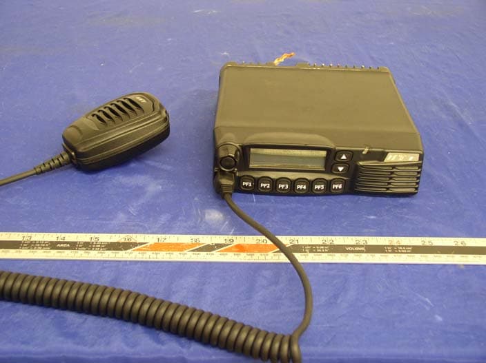
Click to zoom
Application Details
- Equipment Class
- TNF - Licensed Non-Broadcast Transmitter Held to Face
- Date of Grant
- Jul 01, 2005
- Application Purpose
- Original Equipment
- Date of Application
- Jul 01, 2005
- Equipment Note
- Two Way Radio
- Frequency Range
- 136.00000000 - 174.00000000
- Country
- China
Documents & Files
Document Text
Text extracted from the exhibit documents filed with the FCC. Open a document above to read the original.
Users Manual
THANK YOU!Thank you for your purchase of HYT mobile radio TM-800. We believethis easy-to-use radio will provide you with dependable and reliablecommunications at peak efficiency. Please read this manual carefullybefore use. The information presented herein will help you to derivemaximum performance from your radio.MODELS COVERED IN THIS MANUALTM-800 UHF Mobile RadioTM-800 VHF Mobile Radio 2005-6-29, 10:16 1 z Do not touch the metal surface of the radio while it is in use. z Do not mount the radio such that the chassis can come in contact with skin. z High temperatures may burn you skin. CAUTION 1 2005-6-29, 10:16 2 z Vehicle installation: The antenna can be mounted at the center of a vehicle metal roof or trunk lid if the minimumsafe distance is observed. Antenna substitution: Don’t substitute any antenna for theone supplied or recommended by the manufacturer orradio dealer. You may be exposing person(s) to excessiveradio frequency radiation. You may contact your radio dealeror the manufacturer for further instructions. Warning Maintain a separation distance from the antenna to person(s) at least 60cm (24inches). MANDATORY SAFETY INSTRUCTIONSTO INSTALLERS AND USERSz Use Only manufacturer or dealer supplied antennas. z Antenna minimum safe distance: 60cm(24 inches). z Antennas used for this transmitter must not exceed anantenna gain of 0 dBd . The FCC (Federal Communications Commission)has adopted a safety standard for humanexposure to RF energy which is below the OSHA(Occupational Safety and Health Act) limits.z Antenna mounting: The antenna supplied by the manu-facturer or radio dealer must not be mounted at a loca-tion such that during radio transmission, any personcan come closer than the above indicated minimum safedistance to the antenna (i.e. 60cm/24inches). z To comply with current FCC RF Exposure limitations, theantenna must be installed at or exceeding the minimumsafe distance indicated above, and in accordance withthe requirements ot the antenna manufacturer orsupplier. 2 “ This transmitter is authorized to operate with a maximumduty factor of 50%, in a typical push-to-talk mode, forsatisfying FCC RF exposure compliance requirements.” 2005-6-29, 10:16 3 ContentsUser Safety, Training, and General Information ---- ---------------------------------------------------------------- 4 Compliance with RF Energy Exposure Standards - ---------------------------------------------------------------- 4 FCC Compliance --------------------------------------------- 5 Precautions ---------------------------------------------------- 5 Product Inspection ------------------------------------------ 7 Radio Installation --------------------------------------------- 8 Radio Overview --------------------------------------------- 10 Basic Operations ------------------------------------------- 14 Turn the Radio On/Off ------------------------------------- 14 Adjust the V olume ------------------------------------------ 14 Monitor --------------------------------------------------------- 14 Select a Channel -------------------------------------------- 15Select a Zone ------------------------------------------------ 15 Receive -------------------------------------------------------- 15 Transmit ------------------------------------------------------- 16 Selectable Power Level ----------------------------------- 16 Beginning / End of Transmission ID -------------------- 16Channel Scan ------------------------------------------------ 17 Busy Channel Lockout (BCL) --------------------------- 19 BCL Override ------------------------------------------------ 19 DTMF Call ----------------------------------------------------- 20 Code Squelch ------------------------------------------------ 22 Auto Transpond --------------------------------------------- 23 Off-Hook Decode ----- -------------------------------------- 23 Time-Out-Timer (TOT) ------------------------------------- 23 Emergency Call ---------------------------------------------- 24 Stun & Revive ------------------------------------------------ 24 Programmable Auxiliary Functions ----------------- 25 Reverse Frequency ---------------------------------------- 25 Talkaround ---------------------------------------------------- 25Selectable Squelch Level --------------------------------- 25 User Selectable Tone (UST) ----------------------------- 26 Public Address ---------------------------------------------- 26 Dual Home Channels --------------------------------------- 27 Horn Alert ----------------------------------------------------- 27 Selectable 2-Tone Encode ------------------------------- 27 Selectable 5-Tone Encode ------------------------------- 27 Display Frequency ----------------------------------------- 28 Display Label ------------------------------------------------- 28Display Mode ------------------------------------------------- 28LCD Backlight ------------------------------------------------ 28 Compander --------------------------------------------------- 28 Scrambler ----------------------------------------------------- 28 GPS Report --------------------------------------------------- 29 Short Message ---------------------------------------------- 29 Status Message --------------------------------------------- 29 Optional Signalling ------------------------------------------ 29 User Set Mode ---------------------------------------------- 31 Appendix 1 Entering Characters --------------------- 50Optional Accessories ---- -------------------------------- 51 3 2005-6-29, 10:16 4 User Safety, Training, and GeneralInformationREAD THIS IMPORTANT INFORMATION ON SAFE ANDEFFICIENT OPERATION BEFORE USING YOUR HYTMOBILE RADIO.Compliance with RF Energy ExposureStandardsYour HYT mobile radio is designed and tested to comply witha number of national and international standards and guide-lines (listed below) regarding human exposure to radio fre-quency electromagnetic energy. This radio complies withthe IEEE and ICNIRP exposure limits for occupational/c…
Text truncated - open the document above for the full version.
External Photos
APPENDIX C - EUT EXTERNAL PHOTOGRAPHS EUT – Front View EUT – Rear View Microphone – Top View Microphone – Bottom View EUT with Microphone View
ID Label/Location Info
APPENDIX A - FCC ID LABELING AND LOCATION Proposed FCC ID Labeling Proposed FCC ID Location Rear Side of EUT / Proposed Label Location ATTENTION! Restricted to occupational use to satisfy FCC RF exposure limits. See users manual for operating requirements. FCC ID: R74TM-800V Model: TM-800V
Operational Description
Circuit Description 1. Frequency Configuration The receiver utilizes double conversion superheterodyne. The first IF is 49.95MHz and the second is 450KHz. The first local oscillator signal is supplied from PLL circuit. The second local oscillator signal ( 50.4MHz ) is generated from the frequency tripling of TCXO (16.8MHz). The PLL circuit generates the frequencies needed in the transmitter Frequency Range: 136 MHz—174MHz 3.1 MIC Circuit and Modulation Circuit The AF signal from MIC is amplified by IC204 after passing through the MIC control switch (Q507). The resulting signal is then amplified by IC106 and pre-emphasized, encoded. It is passed to IC121 (electronic switch) before reaching IC125. The signaling is inputted into IC125 and enters VCO for modulation. 3.2 Power AMP and Post AMP TX-RF signal is outputted from Q703 in VCO circuit and amplified by Q126, Q127 and Q128. The amplified signal is then fed to IC102 and passes through LPF before reaching the antenna terminal. 3.3 APC The APC is used to keep the power output at a constant preset value. D105 and D106 transform the signal from detector into DC voltage which is then compared with the reference voltage from CPU in IC118 and outputted as DC control voltage. The DC control voltage controls the output power by controlling the grid of IC102. 4. PLL PLL circuit generates the first local oscillator signal for reception and the RF signal for transmission. PLL circuit consists of TX frequency oscillator (Q701), RX frequency oscillator (Q702), buffer amplifier (Q703), RF amplifier (Q124), PLL IC (IC801), LPF (Q804, Q805) and TX/RX VCO control switch (Q704, Q706). In transmit mode, IC120 transmits the frequency data to PLL IC. Q704 is turned on to activate TX VCO. The outputted signal is amplified by Q703, Q124, then divided by PLL IC into 2.5KHz, 5KHz or 6.25KHz signal. The divided signal is compared with 2.5KHz, 5KHz or 6.25KHz reference signal from 16.8MHz crystal oscillator (2.5 PPM frequency stability) in the phase comparator. The frequency control voltage outputted from the phase comparator is sent to TX VCO after passing through LPF (Q804, Q805). In the meantime, modulation signal (TX) is passed to TX VCO for frequency modulation. The working principle in receive mode is similar to that in transmit mode. 3. Control Circuit Circuit in this section is comprised of CPU, reset IC, power supply controller and FLASHROM. 3.1 CPU IC120 (CPU) operates at 9.8304MHz. It controls the data transmission between receive circuit, transmit circuit, control circuit, display circuit and peripheral circuit. 3.2 Power Supply Power supply of the radio is derived from the battery which supplies battery B+. D135 and D137 are over-voltage protection diodes. Power-on/off can be controlled by software. Vout provides power supply to IC115, IC114, IC113, IC111, and IC112, which produces 8V, 9V, 5V, and 3.5V voltage to the circuit. 4. Display Circuit Display circuit is comprised of CPU (IC503), LCD module, LED and other components. Radio features are programmable by PF1-PF6. Data is displayed on the 12-digit and 4-digit dot matrix LCD in alphanumeric form.
Parts List/Tune Up Info
Adjustment Description The radio can be adjusted by PC programming software or by manual adjustment. Manual adjustment procedure of TM800 is as follows. (Refer to “Test Mode” and “Adjustment mode” in the section Radio Modes.) Instrument: Radio Communication Test Set 1 set Scanner 1 set 30A/30V Power Supply 1 set Digital Voltmeter 1 set Power Meter 1 set Signal Line (with dummy load) 1 pc Adjustment: 1. Download ● Connect the radio with PC by programming cable; Turn the radio on. ● Click “Download” on software interface; ● Select the desired program and click “Open”, download starts. ● Click “End” when download is completed. ● Turn the radio off and remove the programming cable. 2. Initialization It’s necessary to set the frequency and initialize the radio before adjustment because there is no needed information in FLASHROM when the radio is manufactured. ● Turn the power on while holding down [PF2], then press [PF3], [PF4] and [PF6] in sequence. ● The LED on control panel turns green from red, indicating that the initialization is completed. 3. Adjustment Some items can be adjusted in conventional mode and the others in manual adjust mode. ● Turn the power on to enter conventional mode. ● Switch the power off and back on while holding down [PF6], the radio enters manual adjust mode. The channel number is displayed on the LCD.
RF Exposure Info
§1.1307(b)(1) & §2.1091 - RF EXPOSURE According to §15.247(b)(4) and §1.1307(b)(1), systems operating under the provisions of this section shall be operated in a manner that ensures that the public is not exposed to radio frequency energy level in excess of the Commission’s guidelines. According to §1.1310 and §2.1093 RF exposure is calculated. Limits for Maximum Permissive Exposure (MPE) Frequency Range (MHz) Electric Field Strength (V/m) Magnetic Field Strength (A/m) Power Density (mW/cm 2 ) Averaging Time (minute) Limits for General Population/Uncontrolled Exposure 0.3-3.0 614 1.63 *(100) 6 3.0-30 1824/f 4.89/f *(900/f 2 ) 6 30-300 1.4 0.163 1.0 6 300-1500 / / f/300 6 1500-15000 / / 5 6 f = frequency in MHz * = Plane-wave equivalent power density MPE Prediction Predication of MPE limit at a given distance Equation from page 18 of OET Bulletin 65, Edition 97-01 S = PG/4πR² Where: S = power density P = power input to antenna G = power gain of the antenna in the direction of interest relative to an isotropic radiator R = distance to the center of radiation of the antenna Maximum peak output power at antenna input terminal: 47.17 (dBm ) Maximum peak output power at antenna input terminal: 52119 (mW) Predication frequency: 136 (MHz) Antenna Gain (typical): 2.1 (dBi) Maximum antenna gain: 1.62 (numeric) MPE limit for uncontrolled exposure at prediction frequency: 1.0 (mW/cm^2) Power density at predication distance: 82 cm Test Result The predicted distance at 1.0 mW/cm 2 power density level is 82 cm. The EUT is defined as mobile device.
Test Report
Note: The test report is specially limited to the above company and this particular sample only. It may not be duplicated without prior written consent of Bay Area Compliance Laboratory Corporation. This report must not be used by the client to claim product certification, approval, or endorsement by NVLAP, NIST or any agency of the US Government. FCC PART 90 TYPE APPROVAL EMI MEASUREMENT AND TEST REPORT For SHENZHEN HYT SCIENCE&TECHNOLOGY CO., LTD R2-High-Tech Industrial Park ShenZhen, China FCC ID: R74TM-800V This Report Concerns: Original Report Equipment Type: Mobile Radio Test Engineer: Hang Tan Report No.: R0505025 Report Date: 2005-06-08 Reviewed By: Daniel Deng Prepared By: Bay Area Compliance Laboratory Corporation 230 Commercial Street Sunnyvale, CA 94085 Tel: (408) 732-9162 Fax: (408) 732 9164 Shenzhen HYT Science&Technology Co.,Ltd FCC ID: R74TM-800V Report # R0505025Rpt-a Page 2 of 26 FCC Part 90 Type Approval Report TABLE OF CONTENTS GENERAL INFORMATION.......................................................................................................................................4 PRODUCT DESCRIPTION FOR EQUIPMENT UNDER TEST (EUT) ....................................................................................4 OBJECTIVE...................................................................................................................................................................4 RELATED SUBMITTAL(S)/GRANT(S).............................................................................................................................4 TEST METHODOLOGY..................................................................................................................................................4 TEST FACILITY.............................................................................................................................................................4 SYSTEM TEST CONFIGURATION ..........................................................................................................................6 JUSTIFICATION.............................................................................................................................................................6 BLOCK DIAGRAM.........................................................................................................................................................6 EQUIPMENT MODIFICATIONS.......................................................................................................................................6 TEST SETUP BLOCK DIAGRAM.....................................................................................................................................6 SUMMARY OF TEST RESULTS ...............................................................................................................................7 §2.1046 - CONDUCTED OUTPUT POWER..............................................................................................................8 PROVISION APPLICABLE...............................................................................................................................................8 TEST PROCEDURE........................................................................................................................................................8 TEST EQUIPMENT.........................................................................................................................................................8 ENVIRONMENTAL CONDITIONS....................................................................................................................................8 TEST RESULTS.............................................................................................................................................................8 §2.1047, §90.207 - MODULATION CHARACTERISTIC ......................................................................................10 APPLICABLE STANDARD............................................................................................................................................10 TEST PROCEDURE......................................................................................................................................................10 TEST EQUIPMENT.......................................................................................................................................................10 ENVIRONMENTAL CONDITIONS..................................................................................................................................10 TEST RESULTS...........................................................................................................................................................10 §2.1049, AND § 90.209 – OCCUPIED BANDWIDTH .............................................................................................14 APPLICABLE STANDARD............................................................................................................................................14 TEST PROCEDURE......................................................................................................................................................14 TEST EQUIPMENT.......................................................................................................................................................14 ENVIRONMENTAL CONDITIONS..................................................................................................................................15 TEST RESULTS...........................................................................................................................................................15 §2.1051 AND §90.210 - SPURIOUS EMISSIONS AT ANTENNA TERMINALS ................................................19 APPLICABLE STANDARD.........................................................................................…
Text truncated - open the document above for the full version.
Contact Information
Applicant
Xiong Lei
Test Firm
Bay Area Compliance LaboratoryJohn Chan
Technical Specifications
| # | Rule Parts | Frequency Range | Power Output | Emission | Tolerance |
|---|---|---|---|---|---|
| 2 | 9 | 136 MHz - 174 MHz | 52.119 W | 16K0F3E | 2.5 ppm |
Other Applications from Shenzhen HYT Science &Technology Co Ltd

R74TR-800U1
Feb 26, 2008REPEATER (BASE STATION)
Equipment Class
TNB - Licensed Non-Broadcast Station Transmitter
R74TR-800U2
Feb 24, 2008REPEATER BASE STATION
Equipment Class
TNF - Licensed Non-Broadcast Transmitter Held to Face
R74TR-800V
Feb 20, 2008REPEATER (BASE STATION)
Equipment Class
TNB - Licensed Non-Broadcast Station Transmitter
R74TC-620V2
Feb 18, 2008Two-Way Radio
Equipment Class
TNF - Licensed Non-Broadcast Transmitter Held to Face
R74TC-980U1
Jan 14, 2008TWO-WAY RADIO
Equipment Class
TNF - Licensed Non-Broadcast Transmitter Held to Face