R8VDASDEC-1ENEAS ENCODER/DECODER
Digital Alert Systems, Inc.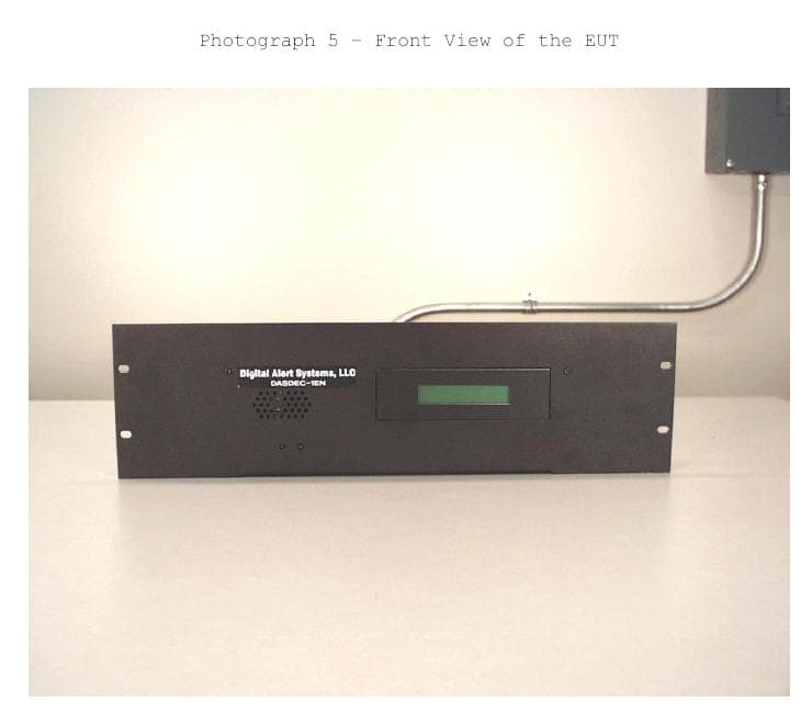
Click to zoom
Application Details
- Equipment Class
- EAD - Part 11 Emergency Alert Devices
- Date of Grant
- Aug 19, 2004
- Application Purpose
- Original Equipment
- Date of Application
- Jun 09, 2004
- Equipment Note
- EAS ENCODER/DECODER
- Company
- Digital Alert Systems, Inc.
- Country
- United States
Documents & Files
Document Text
Text extracted from the exhibit documents filed with the FCC. Open a document above to read the original.
Users Manual
DASDEC Digital Emergency Alert System Encoder/Decoder Users Manual Model DASDEC-1EN Version 1.0 Digital Alert Systems,LLC PO Box 5107 Oracle, AZ 85623-5107 www.digitalalertsystems.com Copyright © 2004. Digital Alert Systems, LLC All Rights Reserved. DASDEC is a Trademark of Digital Alert Systems,LLC Chyron CODI is a Trademark of Chyron Corporation NDU is a Trademark of Vela Inc. All other Trademarks are hereby acknowleged. FCC Information FCC ID: R8VDASDEC-1EN The DASDEC is fully compliant with FCC Part 11. This equipment has been tested and found to comply with the limits for a Class A digital device, pursuant to Part 15 of the FCC Rules. These limits are designed to provide reasonable protection against harmful interference when the equipment is operated in a commercial environment. This equipment generates, uses, and can radiate radio frequency energy and, if not installed and used in accordance with the instruction manual, may cause harmful interference to radio communications. Operation of this equipment in a residential area is likely to cause harmful interference in which case the user will be required to correct the interference at his own expense.
Users Manual
Digital Alert Systems, LLC – DASDEC 1.0 Users Manual – Contents 1 Table of Contents 1. Getting Started with the DASDEC 1.1. Introduction 1.2. Features 1.3. TDX - Textual Data Exchange 2. The Emergency Alert System 2.1. Purpose 2.2. Operation 3. DASDEC Hardware and Setup 3.1. Introduction 3.2. Front Panel 3.2.1. LCD 3.2.2. Status LEDs 3.3. Back Panel Connectors 3.4. Audio Wiring 3.5. GPI Output relays 4. DASDEC Operation 4.1. Power Up and Initial Setup 4.1.1. Starting the DASDEC 4.1.2. Using a VGA monitor, keyboard, and mouse with a DASDEC 4.1.3. Using a browser on a networked computer 4.2. Network Configuration 4.2.1. Default network setup 4.2.2. Setting the IP address using DHCP 4.2.3. Setting the IP address manually 4.2.4. External address 4.2.5. Network status information 4.3. Server Configuration 4.3.1. Server Name 4.3.2. DASDEC Clock 4.3.3. Password 4.3.4. Optional Features 4.3.5. Audio levels and tone testing 4.4. Decoder Setup 4.4.1. Station ID 4.4.2. EAS ORG type 4.4.3. Auto-Forward EAS Types Setup 4.4.4. Auto-Forward FIPS Locations Setup 4.4.5. Audio Input Configuration 4.5. Decoder Status Digital Alert Systems, LLC – DASDEC 1.0 Users Manual – Contents 2 4.6. Encoder Setup 4.6.1. Common EAS type pool Setup 4.6.2. Common EAS FIPS locations pool Setup 4.6.3. One Button Alert Configuration 4.7. Encoder Operation 4.7.1. Sending EAS alerts 4.7.2. About TDX 4.7.3. One Button send alerts 4.7.4. Originated Alert status 4.7.5. Audio output configuration 5. DASDEC Network Protocol 6. DASDEC Peripherals 6.1. Vela NDU 6.2. Texscan character generator 6.3. Chyron CODI character generator 7. Troubleshooting
Users Manual
Digital Alert Systems, LLC - DASDEC 1.0 Users Manual Table of Contents 1.Getting Started with the DASDEC 1.1.Introduction 1.2.Features 2.The Emergency Alert System 2.1.Purpose 2.2.Operation 2.3.Management 2.4.Your responsibility as a broadcaster 2.5.Future of EAS and DASDEC 3.DASDEC Hardware and Setup 3.1.Introduction 3.2.Front Panel 3.2.1.LCD 3.2.2.Status LEDs 3.3.Back Panel Connectors 3.4.Audio Wiring 3.5.GPIO Output relays 4.DASDEC Operation 4.1.Power Up, User Interface and Initial Setup 4.1.1.Using a VGA monitor, keyboard, and mouse with a DASDEC 4.1.2.Directly connecting a networked host computer 4.1.3.LAN connection with a networked host computer 4.2.Web Server Login 4.2.1. Product License Key Configuration 4.3.Network Configuration 4.3.1.Default network setup 4.3.2.Setting the IP address using DHCP 4.3.3.Setting the IP address manually 4.3.4.Network status information 4.4.Server Configuration 4.4.1.Setup Server Page 4.4.1.1.DASDEC platform ID 4.4.1.2.Server Name 4.4.1.3.Access Security Configuration 4.4.1.4.Product License Key Entry 4.4.1.5.Restart 4.4.1.6.Software Upgrade 4.4.2.DASDEC Clock and NTP Digital Alert Systems, LLC - DASDEC 1.0 Users Manual 4.4.3.Admin Password 4.4.4.Email Server 4.4.5.Audio levels and tone testing 4.5.Decoder Setup 4.5.1.Station FIPS ID 4.5.2.Decoder Auto-Forwarding Setup 4.5.2.1.EAS ORG Type 4.5.2.2.EAS Station ID 4.5.2.3.Auto-Forward EAS Types Setup 4.5.2.4.Auto-Forward FIPS Locations Setup 4.5.3.Audio Input Configuration 4.6.Decoder Event Status 4.7.Forwarded Event Status 4.8.Encoder Setup 4.8.1. General Encoder Setup 4.8.1.1.EAS ORG Type 4.8.1.2.EAS Station ID 4.8.1.3. EAS Types Pool Configuration 4.8.1.4. EAS FIPS Locations Pool Configuration 4.8.2.Required Tests Encoder Setup 4.8.3.Audio Encoder Configuration 4.9.Encoder Operation 4.9.1.Sending EAS alerts 4.9.2.One Button send alerts 4.9.3.Originated Alert status 4.10.Testing DASDEC Encoding and Decoding 5.DASDEC Peripherals 5.1.Vela NDU 5.2.Other Character generator 6.Appendix
Users Manual
Digital Alert Systems, LLC - DASDEC 1.0 Users Manual 1 1.Getting Started with the DASDEC 1.1.Introduction The DASDEC is an Emergency Alert System (EAS) Digital Encoder/Decoder platform. The DASDEC is built with the latest digital PC computer technology. The DASDEC encoding/decoding technology is software based, and is built upon the Linux OS. The DASDEC core hardware is a standard PC motherboard and digital audio sound cards. The DASDEC is easy to upgrade, not requiring custom ROMS. The DASDEC also exploits the benefits of modern network technology. It is fully operable over a LAN using secure network protocols. In addition, it supports existing methods of device control using a serial port. The DASDEC is representative of the continuing advance of digital device technology into technological areas that only a few years ago required custom hardware. 1.2.Features The DASDEC provides a number of features for easier management of FCC EAS requirements. The DASDEC has been designed to improve the EAS system for radio and TV broadcasters, Cable TV headend facilities, LP1 and LP2 designated stations, and Public Safety and Emergency Service personnel. DASDEC hardware specs • 2x20 backlit LCD display for monitoring unit and decoder status • Operational status LED • Alert decoding/output LED • Cool running, low power CPU • Ethernet port for network access • Base unit has one 3.5mm mini-jack audio input port that supports scanning/decoding EAS on 2 radio channels • Hard drive or flash drive options • 3.5mm mini-jack stereo audio output port • 3.5mm mini-jack microphone input • 1 RS-232 Serial port, supports TFT-911 serial control protocol Digital Alert Systems, LLC - DASDEC 1.0 Users Manual 2 • 1 parallel port will support a variety of printers • 4 USB ports - will support extra serial ports, printers, modems,wireless ethernet, flash drives,etc • 2 Firewire ports • VGA out for console or desktop GUI interface • one NTSC/PAL video output • standard PS/2 keyboard/mouse ports • supports PCI expansion card, use with audio card for scanning 2 more audio inputs (total of 4 EAS audio sources) • internal speaker for monitoring • can be safely powered off/on without disk damage • optional GPI input/output and balanced audio output module. DASDEC general software features/specs • Linux 2.4.24 operating system • Built in multi-user, password protected Web interface for control/status/monitoring of all activity. Web interface supports SSL. • KDE desktop available via directly connected keyboard/mouse/VGA monitor • Supports sending email for decoded/forwarded/originated alerts • Support SMS pager output using USB modem • Socket based network interface for monitoring/control • Supports WiFi wireless networking via USB • Supports a variety of printers via USB/Parallel • Supports operational status indication via LED and LCD • Web interface for software update • Support for optional GPI input to trigger actions and optional GPI output during alerts. DASDEC decoder features • Decodes FCC EAS codes and NOAA SAME codes. • Automatic audio level correction for reliable operation. • Supports fully unattended operation. • Supports manual and selectable automatic alert auto-forwarding. • Easy to use web interface for configuration of auto-forwarding locations and codes. • Web interface makes it easy to review and print logs of active and expired decoded/forwarded alerts. • Stores user configurable number of previous alerts. • Supports multiple simaltaneously active decoded alerts. • Configurable audio output port selection for alert forwarding. • Decoding status displayed on unit LCD and LED. Digital Alert Systems, LLC - DASDEC 1.0 Users Manual 3 • Stores each audio section of EAS alerts into digital files. • Supports TFT-911 serial protocol for alert alert audio playback and alert translation data transfer • Will support scanning up to 6 input channels (depends on hardware expansion) DASDEC Encoder features • Easy to use Web interface for creating and sending FCC EAS alerts. • Web interface makes it easy to configure commonly used locations and alert types. • Web interface makes it easy to review and print logs of active and expired originated alerts. • All audio sections of encoded alerts are stored into separate digital audio files. • Stores user configurable number of previous originated alerts. • Supports multiple simaltaneous active originated alerts. • Configurable audio output port selection for originated alerts • Automatic randomized Weekly test generation • User programmable length of 8 to 30 seconds for FCC EAS 853 Hz and 960 Hz Two-tone Attention Signal. • Web interface upload feature for digital audio files makes it easy to encode the audio portion of EAS alerts. • Supports direct recording of EAS alert audio into digital files. • Audio output level control via web interface. Digital Alert Systems, LLC - DASDEC 1.0 Users Manual 4 2.The Emergency Alert System 2.1.Purpose According to the FCC, "The EAS is designed to provide the President with a means to address the American people in the event of a national emergency. Through the EAS, the President would have access to thousands of broadcast stations, cable systems and participating satellite programmers to transmit a message to the public. The EAS and its predecessors, CONELRAD and the Emergency Broadcast System (EBS), have never been activated for this purpose. But beginning in 1963, the President permitted state and local level emergency information to be transmitted using the EBS." But the EAS system is used for much more than to support a method of communication that has never been (and hopefully never will be) used. The EAS system provides state and local officials with a method to quickly send out important local emergency information targeted to a specific area. This includes weather alerts as well as other local emergency alerts such as child abductions and disasters. The EAS system also has test alerts which are run on a weekly and monthly basis in …
Text truncated - open the document above for the full version.
Block Diagram
DASDEC-1EN Block diagram July 14, 2004 VIA EPIA M mainboard Soundblaster PCI Card (optional) Front Panel 5.25” bay mount 2x20 LCD Serial port pin header Main Audio Line-Out Line-In Mic-In Mini jacks Two Front Panel Status LED’s VIA CPU chipset DASDEC Chassis with Front Panel 120V AC ATX Power supply External AC Power On board Audio, 4 USB, 2 IEEE1394, VGA, Serial Port, Parallel Port, PS/2 Mouse and keyboard connectors PCI riser 4 USB PS/2 mouse & keyboard connectors VGA Out Parallel port Optional Audio Line-Out Line-In Mic-In Mini jacks DASDEC-1EN Di gitalAlertSystems Hard Drive & LCD Power cables IDE Hard drive IDE 0 Audio Monitor Speaker behind Front Panel Power switch ©Digital Alert Systems, LLC 2004 The DASDEC-1EN EAS Encoder/Decoder is a an embedded PC motherboard device that is completely software driven. It is controlled over a LAN or by a desktop browser interface using the built in VGA output, mouse, and keyboard. Two external mono EAS audio sources (from a radio, EAS encoder, soundcard, etc) can be connected to each Audio Line-Input to decode two EAS sources per input. Any audio output can be selected for EAS encoded audio output. 2 EAS Audio Sources 2 IEEE1394 2 EAS Audio Sources RS-232 Serial port LAN Ethernet
Cover Letter(s)
FCC, Laboratory Division Equipment Authorization Branch 7435 Oakland Mills Road Columbia, MD 21046 Dear Sir or Madam: I have attached a pdf of the test of the DASDEC-1EN under Test Report Serial Number 73-7972 completed by Communication Certification Lab. in Salt Lake City, Utah. It includes: Section 1.0Client Information Section 2.0Equipment Under Test (EUT) Section 3.0Test Specifications, Methods and Procedures Section 4.0Operation of EUT During Testing Section 5.0Summary of Test Results Section 6.0Measurements, Examinations, and Derived Results Appendix 1 Test Procedures and Test Equipment Appendix 2Photographs This test document provides block diagrams, and photographs or the DASDEC-1EN. Further to this testing Digital Alert Systems, LLC, has operated the EUT in communications with FCC certified EAS encoder/decoder equipment from TFT and SAGE under encoder/decoder operations defined in Subpart B - Equipment Requirements of the R&O & FNPRM Released: December 9, 1994. Please let me know if additional information is needed. Respectfully Submitted, Bruce Robertson Member/Manager cell 520-488-8667 [email protected] Digital Alert Systems, LLC PO Box 5107 Oracle, AZ 85623-5107 520-896-0303
Cover Letter(s)
Attn: Linda Elliott and Stan Lyles FCC Application Processing Branch Re: FCC ID R8VDASDEC-1EN Applicant: Digital Alert Systems, LLC 731 Confirmation Number: EA648254 Digital Alert Systems,LLC requests to cancel any confidentiality for any of the files submitted to the FCC for the DASDEC-1EN product. Any earlier request for confidentiality was by accident and was unintentional. We authorize the FCC to remove any confidentiality requests that may have been made for any of the submitted exhibits for FCC ID R8VDASDEC-1EN. Thank You, Tom Wood **Digital Alert Systems,LLC*** [email protected] [email protected]
ID Label/Location Info
Digital Alert Systems,LLC FCC ID: R8VDASDEC-1EN FCC Correspondence Reference Number: 27021 FCC 731 Confirmation Number: EA648254 FCC Identification Label for DASDEC-1EN. Here are two drawings of the label to be used on the back panel of the DASDEC-1EN. Below is an photograph showing the placement of the label on the device. The back of the device is 11 in wide. Actual size of label
Operational Description
Operational Information Concerning FCC ID: R8VDASDEC-1EN The DASDEC is fully complient with FCC Part 11. The DASDEC is a PC platform based on the VIA EPIA mainboard. It uses PCI soundcards and onboard audio for input of EAS audio signal sources and to output EAS encoded audio. It provides a Web based user interface to fully configure and operate the device. It has a backlit LCD display and 2 LEDs on the front panel for indicating decoding/encoding status. It provides a serial port and network interface for operational control.
Parts List/Tune Up Info
Input Characteristics Input Range: 90~132/180~264V AC, Manual Selection Frequency: 47~63Hz Input Current: 4A (RMS) @115V AC, 2A (RMS) @230V AC Inrush Current: 50A Max for 115V AC, 80A Max for 230V AC Cold start Features • • • • • • • • • • • Complied with Flex ATX standard High efficiency and reliability Remote On/Off function Internal 12V DC fan included Noise Killer (Thermal fan speed control function) Low noise and ripple Complies with FCC part 15 subpart J Class B and CISPR 22 Class B Output over voltage, short circuit, and over current protection 100% Hi-pot, ATE, and burn-in tested Re-settable power shut down Approved by UL 1950, CSA C22.2 Level 3, TUV EN60950, NEMKO EN60950 (CB Report) Sparkle Power Inc. A Leading Power Supply manufacturer Web site: www.sparklepower.com FSP150-50PL 150 Watts Flex ATX Switching Power Supply Specification • • • • • • • • • • Temperature Range: Operating 0° C ~ +35° C on full load; storage & shipping -20° C ~ +80° C Humidity: 95% on operating and 95% on storage Dielectric Withstand: Input to frame ground 1800V AC for 1 second Efficiency: 68% at minimum measured at nominal AC main voltage and frequency with maximum load on all output Rise Time: Less than 20ms Hold-up Time: 17ms minimum at nominal input voltage Power Good Signal: Power on delay time 100 ms to 500 ms, off delay 1ms minimum (TTL and CMOS compatible) Leakage Current: Not exceed 0.75mA at 115V AC, 60Hz MTBF: 50,000 hours on maximum load at +25° C degree Dimension (WxHxL): 81.5x40.5x150mm/3.2”x1.6”x6” inches Output Characteristics Output Voltage Minimum Load Maximum Load Load Reg. Line Reg. Ripple & Noise +3.3V 0.2A 10.0A ± 5% ± 1% 50mV P-P +5V 1.0A 14.0A ± 5% ± 1% 50mV P-P +12V 0.2A 4.2A ± 5% ± 1% 120mV P-P -12V 0.0A 0.3A ± 10% ± 2% 120mV P-P +5Vsb 0.0A 2.0 A ± 5% ± 1% 100mV P-P *+5V and +3.3V total output not exceed 85W *+3.3V, +5V, and +12V total output cannot exceed 136.4W Sparkle Power Inc. Main Office 1000 Rock Avenue San Jose, CA 95131 TEL: 408-519-8888 FAX: 408-519-9999 E-MAIL: [email protected] Sparkle Power Inc. Los Angeles Office 17071 Green Drive City of Industry, CA 91745 TEL: 626-839-7180 FAX: 626-839-3395 Sparkle Power Inc. Colorado Office 1316 Indian Paintbrush Lane Longmont, CO 80503 TEL: 303-776-3281 FAX: 303-776-7645
Schematics
DASDEC-1EN Schematics July 14, 2004 The DASDEC-1EN ES Encoder/Decoder is constructed from commercially available PC platform hardware. The DASDEC software can run upon a wide variety of hardware. The specific hardware chosen for the DASDEC-1EN was based on specific features and price. The VIA EPIA-M motherboard was chosen. This is of course the heart of the system. Other important parts include an 2x20 character LCD display, IDE hard drive or flash drive, RAM memory, an optional sound card, 2 status LED’s, and a simple speaker. The chosen LCD is the LK202-25 from Matrix Orbital. The DASDEC-1EN is controlled via a LAN and/or external Serial Port and/or by Keyboard/Mouse/VGA monitor display . It displays state via the LCD and also via a VGA monitor. Here is a diagram of the overall schematics of the DASDEC-1EN, which is in essence, a personal computer equipped with an LCD: See below for the layout of the VIA motherboard and the Matrix Orbital LCD. VIA Motherboard LCD for Alert information Internal S peaker Status LED’s: System and Alert Status IDE Hard Drive Optional PCI Card RAM module On Board Ports – Serial,Audio,etc DASDEC oriented VIA motherboard schematic & layout Important Connector Pinouts: For more details refer to VIA Users Manual for EPIA-M series. Other VIA Chipset components DIMM 256MB MEM VIA Eden Or C3 CPU ATXPWR – from Power Supply. To Hard Drive and LCD IDE1 – To Hard Drive IDE2 PCI – Riser card to horizontal PCI Card Floppy Disk- Unused CMOS Batter y COM2 to LCD USB ¾ to Ext Ports Power on, Connector to Speaker Standard PC Pinout IEEE1394 ½ to Ext Ports IEEE 1394 Ports 1/2 USB Ports 3/4 Top: RJ45 to LAN Bottom: USB Ports 1/2 VGA Out Top: PS/2 Mouse Bottom: PS/2 Keyboard Audio Block: Blue: Audio Line-In Green: Audio Line-Out Pink: Audio Mic-In Top: Parallel Port Bottom: Left: S-Video Middle: RCA/SPDIF Right: COM1 Serial for External Device control Pin 1 COM2 Serial Port Pin 9 Pin 2 Pin 1 Power On, Speaker Pin 15 Pin 2 Pin 6: Power On+ Pin 7: Speaker+ Pin 8:Power On- Pin 13: Speaker - Upper Deck Port Block Matrix Orbital LK202-25 LCD schematic: * Connector Function * General Purpose Outputs 2 Status LEDs, optional GPO relay control GPO1 Green LED System status GPO2 Red LED EAS Alert status GPO3-6 available for external GPO relay control 4 pin power LCD power ( 5.0VDC), unused I2C comm. Pin1 +7 to +15 VDC Pin2 I2C SCL clock Pin3 I2C SDA data Pin4 Ground 10 pin keypad header generate 25 key states-optional GPI input DB-9F RS-232 connection to VIA motherboard COM2 serial port Pin2 Data from LCD Pin3 Data to LCD For more details refer to Matrix Orbital Users Manual for LK202-25. Power Connector RS-232 10 pin keypad header General Purpose outputs Pin 1 Pin 4 Pin 5 Pin 1 GPO 1 GPO 6 ©Digital Alert Systems, LLC 2004
Test Report
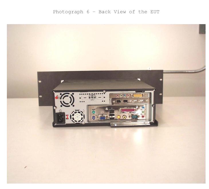
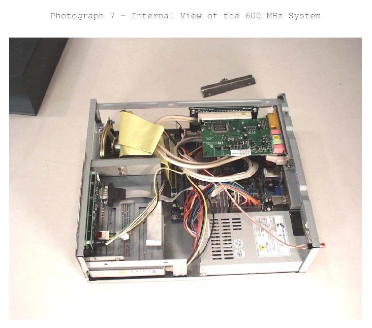
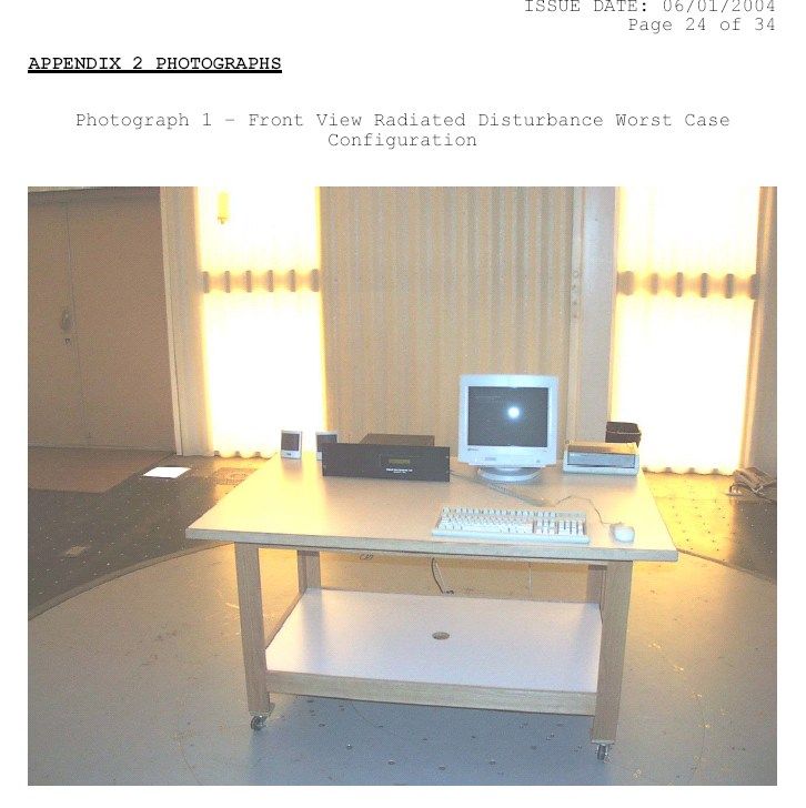
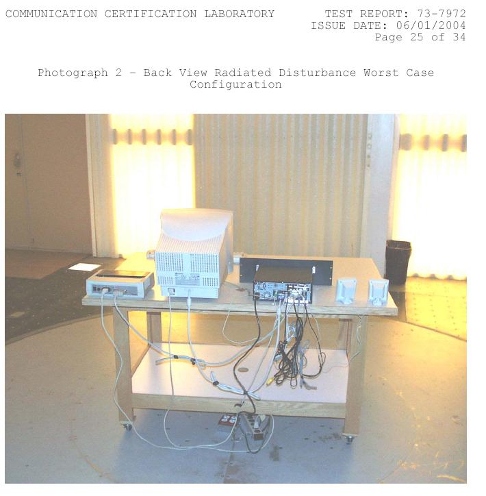
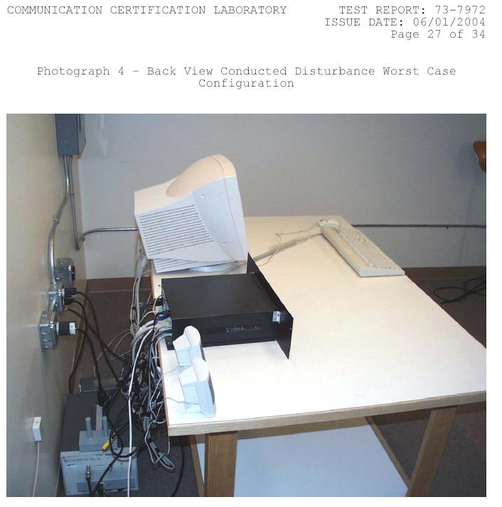
TEST REPORT FROM: COMMUNICATION CERTIFICATION LABORATORY TEST OF: DASDEC-1EN To FCC PART 15, Subpart B ICES-003 Test Report Serial No: 73-7972 TEST REPORT FROM: COMMUNICATION CERTIFICATION LABORATORY 1940 W. Alexander Street Salt Lake City, Utah 84119-2039 Type of Report: Verification TEST OF: DASDEC-1EN To FCC PART 15, Subpart B ICES-003 Test Report Serial No: 73-7972 Applicant: Digital Alert Systems, LLC. 2977 Morningside Dr. Salt Lake City, UT 84124 Date of Test: June 1, 2004 Issue Date: June 1, 2004 Equipment Receipt Date: June 1, 2004 COMMUNICATION CERTIFICATION LABORATORY TEST REPORT: 73-7972 ISSUE DATE: 06/01/2004 Page 2 of 34 CERTIFICATION OF ENGINEERING REPORT This report has been prepared by Communication Certification Laboratory to document compliance of the device described below with the Class A requirements of Federal Communications Commission (FCC) Part 15, Subpart B and Industry Canada (IC) ICES-003. This report may be reproduced in full, partial reproduction may only be made with the written consent of the laboratory. The results in this report apply only to the sample tested. - Applicant: Digital Alert Systems, LLC. - Manufacturer: Digital Alert Systems, LLC. - Brand Name: DAS - Model Number: DASDEC-1EN On this 1 st day of June 2004, I, individually, and for Communication Certification Laboratory, certify that the statements made in this engineering report are true, complete, and correct to the best of my knowledge, and are made in good faith. Although NVLAP has recognized that the Communication Certification Laboratory EMC testing facilities are in good standing, this report must not be used to claim product certification, approval, or endorsement by NVLAP, NIST, or any agency of the federal government. COMMUNICATION CERTIFICATION LABORATORY Checked by: Thomas C. Jackson President Tested by: Norman P. Hansen EMC Technician COMMUNICATION CERTIFICATION LABORATORY TEST REPORT: 73-7972 ISSUE DATE: 06/01/2004 Page 3 of 34 TABLE OF CONTENTS PAGE SECTION 1.0 CLIENT INFORMATION .................................4 SECTION 2.0 EQUIPMENT UNDER TEST (EUT) ..........................5 SECTION 3.0 TEST SPECIFICATION, METHODS & PROCEDURES ...........9 SECTION 4.0 OPERATION OF EUT DURING TESTING ...................12 SECTION 5.0 SUMMARY OF TEST RESULTS ...........................14 SECTION 6.0 MEASUREMENTS, EXAMINATIONS AND DERIVED RESULTS .....15 APPENDIX 1 TEST PROCEDURES AND TEST EQUIPMENT ..................20 APPENDIX 2 PHOTOGRAPHS .........................................24 APPENDIX 3 FCC Part 15/ICES-003 COMPLIANCE INFORMATION .........32 COMMUNICATION CERTIFICATION LABORATORY TEST REPORT: 73-7972 ISSUE DATE: 06/01/2004 Page 4 of 34 SECTION 1.0 CLIENT INFORMATION 1.1 Applicant: Company Name: Digital Alert Systems, LLC. 2977 Morningside Dr. Salt Lake City, UT 84124 Contact Name: Tom Wood Title: Principle Engineer 1.2 Manufacturer: Company Name: Digital Alert Systems, LLC. P.O. Box 5107 Oracle, AZ 85623-5107 Contact Name: Bruce Robertson Title: Manager COMMUNICATION CERTIFICATION LABORATORY TEST REPORT: 73-7972 ISSUE DATE: 06/01/2004 Page 5 of 34 SECTION 2.0 EQUIPMENT UNDER TEST (EUT) 2.1 Identification of EUT: Brand Name: DAS Model Name or Number: DASDEC-1EN Serial Number: None Options Fitted: See Section 2.3 Country of Manufacture: U.S.A. 2.2 Description of EUT: The DASDEC-1EN is a rack mounted decoder and encoder of Emergency Alert System signals. The signal is brought into the EUT on the Audio Line In port and, after processing, is output the Audio Out/Speaker ports. The unit has Ethernet and serial ports for control purposes. A parallel printer port is available for logging purposes. USB and Composite video ports are available for expansion purposes, although, at this time the expansion is undefined. Monitor, mouse, and keyboard ports are not typically connected, but on occasion may be and for this testing these devices were attached to the EUT. Two versions of the DASDEC-1EN were tested. The difference is in the main processor board and the sound card. The tables below show the internal configurations of the DASDEC-1EN devices tested. The worst-case emissions were seen during testing of the configuration with the VIA ME6000 main board and the results in this report are from testing this configuration. 600 MHz System Component Description VIA ME6000 Main computer board and processor FSP Group FSP150-50PL Power supply Speaker Internal speaker Maxtor 20 GB Hard drive Matrix Orbital LCD Display Display module Seal SSC-2 Sound Card COMMUNICATION CERTIFICATION LABORATORY TEST REPORT: 73-7972 ISSUE DATE: 06/01/2004 Page 6 of 34 1000 MHz System Component Description VIA ME10000 Main computer board and processor FSP Group FSP150-50PL Power supply Speaker Internal speaker Maxtor 30 GB Hard drive Matrix Orbital LCD Display Display module Soundblaster PCI 16 Sound Card 2.3 EUT and Support Equipment: The FCC ID numbers for all the EUT and support equipment used during the test (including inserted cards) are listed below: Brand Name Model Number Serial No. FCC ID Number Description Name of Interface Ports / Interface Cables BN: DAS MN: DASDEC-1EN (1) N/A EAS Encoder/ Decoder See Section 2.3 BN: CA MN: Speakers N/A Speakers Audio/Unshielded cable with stereo mini-jack connector (2) BN: Gateway MN: EV500A SN: 15017A444139 BEJCB575B Monitor Video/Shielded attached video cable (2 & 4). BN: HP Thinkjet MN: 2225C SN: 2442S60426 BS46XU222 5C Printer Parallel/Shielded parallel printer cable (2) BN: Keytronics MN: E03601QUS201-C SN: Q990739277 DoC Keyboard Keyboard/Attached PS/2 keyboard cable (2 & 3) BN: Microsoft MN: Intellimouse 1.2A DoC Mouse Mouse/Attached PS/2 mouse cable (2 & 3) COMMUNICATION CERTIFICATION LABORATORY TEST REPORT: 73-7972 ISSUE DATE: 06/01/2004 Page 7 of 34 Brand Name Model Number Serial No. FCC ID Number Description Name of Interface Ports / Interface Cables BN: TrendNet MN: 4 Port None Ethernet Hub Unshielded CAT 5 cables w/RJ45 connectors (2) BN: DAS MN: DASDEC (support sys…
Text truncated - open the document above for the full version.
Test Report
©Digital Alert Systems, LLC 2004 Page 1 DASDEC Compliance to FCC EAS Encoder/Decoder requirements in Part 11.32, 11.33, and 11.34 Digital Alert Systems,LLC - July 2004 Introduction The DASDEC-1EN is a new kind of Emergency Alert System Encoder/Decoder platform. This is because it is built with the latest digital PC computer technology, instead of from custom electronic boards and circuits. The DASDEC encoding/decoding technology is software based, and is built upon the Linux OS. The DASDEC core hardware is a standard PC motherboard and digital audio sound cards. The DASDEC exploits the benefits of modern network technology. It is fully operable over a LAN using secure network protocols. In addition, it supports existing methods of device control using a serial port or ports. The DASDEC is representative of the continuing advance of digital device technology into technological areas that only a few years ago required custom hardware. Compliance Statements What follows is an item-by-item list of the FCC regulations for EAS Encoders and Decoders and how the DASDEC-1EN complies with each regulation. Note: As an aside, a method to incorporate text transmission techniques into the EAS protocol as referenced the 2001 NPRM and the 2002 R&O has been developed by Digital Alert Systems, LLC and is available in the DASDEC if this methodology is accepted. Please reference www.digitalalertsystems.com for information on this methodology. 1994 R&O and FNPRM Adopted: Nov. 10, 1994 Released: Dec. 9, 1994 R&O 12-9-94 ENCODER 11.32 EAS Encoder. (a) EAS Encoders must at a minimum be capable of encoding the EAS protocol described in 11.31 and providing the EAS code transmission requirements described in 11.51. EAS encoders must additionally provide the following minimum specifications: The DASDEC encodes messages into digital audio files (WAV format) using 16000 samples a second. Each encoded file may be played out of an analog audio output port from the sound card (s) into a transmitter or into an EAS decoder. These files are distortion free because they are mathmatically computed. The audio quality of the soundcards is excellent and works well for the purpose of EAS encoding. Reliable communications with the TFT 911 and SAGE Endec, both certified EAS encoder decoder packages, attest to the accuracy of DASDEC EAS encoding. The audio files exactly encode messages in the format described in 11.31 as follows: [PREAMBLE]ZCZC-ORG-EEE-PSSCCC+TTTT-JJJHHMM-LLLLLLLL- (one second pause) (HEADER repeated three times) (transmission of 8 to 25 seconds of Attention Signal) as described in 11.51 (transmission of audio, video or text messages) alert or test audio and text messaging [PREAMBLE]NNNN (END of MESSAGE repeated three times) ©Digital Alert Systems, LLC 2004 Page 2 (1) Encoder programming. Access to encoder programming shall be protected by a lock or other security measures and be configured so that authorized personnel can readily select and program the EAS Encoder with Originator, Event and Location codes for either manual or automatic operation. DASDEC encoder access is via a Web browser interface. The DASDEC acts as a Web server and provides pages for configuration, monitoring, and operation. The interface is available to any HTTP browser, which can access the network to which the DASDEC belongs. Alternately, the same interface can be run directly upon a VGA monitor connected to the DASDEC. The Web interface provides a login page that is password protected. It can be set to use secure socket protocols, and is readily accessible to authorized personnel. The DASDEC is further secured in that it provides a password protected login shell on a VGA monitor and keyboard directly connected to its back plane connectors. The DASDEC is very easy to program EAS alerts because it presents a graphical interface for all required operations on a single page. Since the DASDEC is accessible to computer workstations via a network, simply by using a browser on a workstation, an operator does not have to be physically present at the device in order to encode and send EAS alerts, but he must have the authorizing password…
Text truncated - open the document above for the full version.
Contact Information
Applicant
Anne L Wakeman(COO, GM, VP)
Technical Contact
Digital Alert Systems, LLCTom Wood
[email protected]801-272-0148
2977 Morningside Dr · Salt Lake City, Utah · United States
Non-Technical Contact
Digital Alert Systems, LLCBruce W Robertson
520-896-0303
Test Firm
Nemko-CCL, Inc.Thomas Jackson
Technical Specifications
| # | Rule Parts | Frequency Range | Power Output |
|---|---|---|---|
| 1 | 11 | - | - |
Other Applications from Digital Alert Systems, Inc.

R8VG3DAS01
Aug 10, 2021EAS Encoder/Decoder
Equipment Class
EAD - Part 11 Emergency Alert Devices