R8VG3DAS01EAS Encoder/Decoder
Digital Alert Systems, Inc.
Click to zoom
Application Details
- Equipment Class
- EAD - Part 11 Emergency Alert Devices
- Date of Grant
- Aug 10, 2021
- Application Purpose
- Original Equipment
- Date of Application
- Aug 10, 2021
- Equipment Note
- EAS Encoder/Decoder
- Company
- Digital Alert Systems, Inc.
- Country
- United States
Documents & Files
Document Text
Text extracted from the exhibit documents filed with the FCC. Open a document above to read the original.
Users Manual
FLEXIBLE EMERGENCY MESSAGING PLATFORM USER MANUAL DASDEC™ III Version X.0 Revision 0621 Digital Alert Systems, Inc. 100 Housel Ave • Lyndonville, NY 14098 www.digitalalertsystems.com Disclaimer DIGITAL ALERT SYSTEMS, INC. MAKES NO WARRANTY OF ANY KIND WITH REGARD TO THIS MATERIAL, INCLUDING, BUT NOT LIM- ITED TO, THE IMPLIED WARRANTIES OF MERCHANTABILITY AND FITNESS FOR A PARTICULAR PURPOSE. Digital Alert Systems shall not be liable for errors contained herein or for incidental or consequential damages in connection with the furnishing, performance, or use of this material. The only warranties for Digital Alert Systems products and services are set forth in the express warranty statements accompanying such products and services. Nothing herein should be construed as constituting an additional warranty. Digital Alert Systems shall not be liable for technical or editorial errors or omissions contained herein. Copyright © 2004-2021Digital Alert Systems, Inc. All rights reserved. Alert Agent™, DASDEC™, EAS-Net™, MultiPlayer™, MultiStation™, One-Net™, OmniLingual™, PureCAP™, PureCAP™ Plus, TDX™, and Triggered CAP Polling™ are trademarks of Digital Alert Systems, Inc. All other trademarks mentioned in this document or website are the property of their respective owners. While every precaution has been taken in the preparation of this document, Digital Alert Systems assumes no responsibility for errors or omissions. Neither is any liability assumed for damages resulting from the use of the information contained herein. Safari is a registered trademark of Apple Inc. CODI is a registered trademark of Chyron Corporation. Chrome is a registered trademark of Google Inc. VDS-830, VDS-840, Starmu and Star-8 are trademarks of Keywest Technology, Inc. Internet Explorer is a registered trademark of Microsoft Corporation Firefox is a registered trademark of the Mozilla Foundation SqueezeMax is a trademark of Utah Scientific, Inc. Contact Information: Digital Alert Systems, Inc. 100 Housel Ave • Lyndonville, NY 14098-9508 FCC Information FCC ID: R8VXXXXXX-XXX The DASDEC-III complies with Part 11 (47 CFR 11) of the FCC’s rules for EAS encoders and decoders, including a Declaration of Conformity for Common Alerting Protocol (CAP) compliance, and are registered with the FCC under identification number: R8VXXXXXX-XXX. This equipment has been tested and found to comply with the limits for a Class A digital device, pursuant to Part 15 of the FCC Rules. These limits are designed to provide reasonable protection against harmful interference when the equipment is operated in a commercial environment. This equipment generates, uses, and can radiate radio frequency energy and, if not installed and used in accordance with the instruction manual, may cause harmful interference to radio communications. Operation of this equipment in a residential area is likely to cause harmful interference in which case the user will be required to correct the interference at his/her own expense. Sales & Technical Support: Office: 585-765-2254 Table of Contents INTRODUCTION to the DASDEC™ III ........................................................................ i Icons ...................................................................................................................... i Highlights .............................................................................................................. ii Organization ......................................................................................................... ii Conventions .......................................................................................................... ii Chapter 1: Hardware Overview ........................................................................... 1-1 Introduction....................................................................................................... 1-1 Front Panel ........................................................................................................ 1-1 Back Panel ......................................................................................................... 1-3 Chapter 2: Hardware Connections ....................................................................... 2-1 Installation ......................................................................................................... 2-1 Network Connections ........................................................................................ 2-1 Radio Antennas ................................................................................................. 2-2 Audio Wiring ...................................................................................................... 2-2 AES Digital Audio Wiring .................................................................................... 2-4 Video Wiring ...................................................................................................... 2-4 General Purpose Input/Output (GPIO) .............................................................. 2-5 Serial Port Wiring .............................................................................................. 2-6 Power Connections ........................................................................................... 2-7 Chapter 3: Initial Setup ....................................................................................... 3-1 Making First Contact ......................................................................................... 3-1 Web Interface Login .......................................................................................... 3-3 Chapter 4: Web Interface and Navigation ........................................................... 4-1 Tabs, Buttons, Hyperlinks, Pull-Downs, Check Boxes and Text Fields ................ 4-1 Web Interface Layout ........................................................................................ 4-3 Web Interface Navigation .............................…
Text truncated - open the document above for the full version.
Users Manual
DASDEC-III User Manual vX.0 |r0621 5-93 If the EAS device does have a current active custom message alert, that alert will appear on the right side of the page in red. If the NET Decode Custom Message Forwarding is enabled, more options appear. Allow message stop from master NET message originator This option allows the EAS device that sent a custom message via EAS NET to control when the alert is stopped on the receiving EAS device. If this is not enabled, the user would manually stop the alert on the receiving EAS device (if it is before the alert is done). Text Message to Speech Options This drop down menu gives the EAS device the ability to use a text-to-speech engine on EAS NET decoded custom alerts. There are three options: • Never use message text-to-speech • Use message text-to-speech only if Audio not present • Always use message text-to-speech. Ignore Audio if present. Auto-Forward NET decoded Custom Messages This option gives the EAS device the ability to auto forward decoded EAS NET custom messages, even if the EAS device is in Manual Forwarding Mode. FIPS Groups The FIPS Groups sub-tab screen was first introduced within V3.0 software. Throughout the user interface there are numerous places to enter FIPS Location Codes. In an effort to eliminate redundant operations and reduce errors, FIPS code Groups were created. Users can create and modify groups of FIPS Codes in one central area and use those groups throughout the web interface. This screen is also where a list of available encoder FIPS code locations is established. The FIPS Group sub-tab has two sections; Manage FIPS Location Group Lists section and the Configure Available FIPS for Encoder Alert Origination section. Manage FIPS Location Group Lists Screen DASDEC-III User Manual vX.0 |r0621 5-94 Manage FIPS Location Group Lists This section of the screen displays a list of existing FIPS Groups and enables users to add, edit, duplicate and delete FIPS Groups. A brand new EAS device will not have any configured FIPS code groups - they will need to be added on this screen. Add New FIPS Group To create a new FIPS Group click the Add New FIPS Group button. A new FIPS group will appear at the top of the FIPS Location Group Lists and will have an auto- generated name, starting with a series of numbers and ending in ‘_FIPS’. This group will have no defined FIPS codes and will need to be edited. Individual FIPS Groups contain the following information and action buttons: Name Name of the FIPS Group. Use Count Number of times this FIPS Group is used throughout the web interface. FIPS Codes List Displays the first four FIPS codes used in the group, along with a number of FIPS code locations contained in the group. Edit This button opens the edit FIPS Group interface. Here FIPS codes are added and removed in the group and the group name can be edited. Duplicate Group Clicking this button will create a duplicate FIPS Group and place it below the original. It copies the existing group name and adds ‘.CPY’ at the end. Delete Group Users wanting to delete a FIPS Group can click this button. This button is only available to groups not being used throughout the web interface. (See Use Count above.) Once the Delete Group button is clicked, a confirmation screen will appear asking: Are you sure you want to delete the selected FIPS group? User may select either: • Yes, delete group. • No, cancel group deletion! Edit FIPS Group Section DASDEC-III User Manual vX.0 |r0621 5-95 To edit a new or existing FIPS Group, click the corresponding Edit button. User have the ability to change the name and add/remove FIPS codes within this group. The following fields, pull-downs, and buttons are available: Name The EAS device automatically generates a name for new FIPS Group. Highlight the text and enter a descriptive name for this group of FIPS codes. Choose FIPS Subdivision A pull-down menu showing the subdivision setting of the chosen FIPS County. A selection of All should be used unless the county is to be subdivided. To subdivide a county: • Select one of the FIPS Subdivisions options (North, Northeast, West, etc.) • Select a FIPS County • Click the Add button to add that subdivision to the FIPS codes list. Multiple subdivisions of a single county can be added to the FIPS codes list by repeating the above steps. For example, both North Orleans, NY and Northeast Orleans, NY FIPS codes can be added. Choose FIPS State This pull-down contains a list of US States, territories and pre-defined FIPS regions. Select the desired item and the EAS device will populate the Choose FIPS Counties with the FIPS codes available for that area in numeric order. Choose FIPS Counties This area is populated with individual FIPS codes based on the selection made in the Choose FIPS State pull-down menu. It is from this area that FIPS codes are added to the FIPS codes list for the group. Make a selection by clicking on the desired item. Multiple selections can be made by using the CTRL key when clicking items after the first selection. FIPS Codes This area represents a list of FIPS codes used in the group. Only FIPS codes found in this area will be used for processing wherever this FIPS group is selected. FIPS codes are added to this list by selecting the desired codes from the FIPS Counties list and clicking the Add -> button. Items are removed from this list by selecting the item and clicking the Remove Selected button. Add -> Clicking this button will add the selected FIPS Counties to the FIPS codes list area. Remove Selection FIPS code can be removed from the FIPS codes list by selecting the item and clicking the Remove Selected button. Accept Changes This button will finalize any additions, edits, and/or deletions made while editing a FIPS code group. Once clicked, the Edit FIPS group section of the interface will be removed and the screen will return to its normal state. Cancel Changes Pressing this button will cancel any changes made to the FIPS group and return this sc…
Text truncated - open the document above for the full version.
Block Diagram
Mainboard Audio and relay I/O Power Supply Solid State Storage Front Panel Display and Control Speaker E x p a n s i o n E x p a n s i o n Internal Block Diagram Of DASDEC III External Interfaces available but not limited to: Ethernet Sound I/O Digital Video Analog Video Serial USB 1.0, 1.1, 2.0, 3.0 PS/2 Parallel Internal Interfaces available but not limited to: Sound I/O Serial USB 1.0, 1.1, 2.0, 3.0 PCI-E SATA Mainboard Interfaces Power Supply E x p a n s i o n E x p a n s i o n Monitor 4Radio 1 Radio 2Radio 3AES In AES Out Program Audio I/OGPI/OPower Sw Block Diagram of the back panel Front Panel Block Diagram Speaker LED Status Indicators Multi-Line Display Control Interface
External Photos
DASDEC-III Back Panel DASDEC-III Front view DASDED-III Front angle
ID Label/Location Info
DigitalAlertSystems DASDEC-III FCCID:R8VG3DAS01 This device complies with parts 11 and 15 of the FCC Rules DigitalAlertSystems DASDEC-III FCCID:R8VG3DAS01 This device complies with parts 11 and 15 of the FCC Rules ID Label and Location Samplephotoincludingthelabel Enlarged sample of the label
Internal Photos
DASDEC-III Internal GPIO and Radio Module underside Mainboard underside
Operational Description
Brief Product Description DASDEC-III FCC ID: R8VG3DAS01 Operational Overview The DASDEC-III monitors for EAS and CAP alerts using up to 6 audio channels and IP based sources. These channels can include internal AM/FM/NOAA receivers and/or connections to external sources. IP sources are numerous, protocols currently supported are outlined in the user manual. Monitoring of the inputs is achieved using proprietary software that analyzes the audio channels “looking” for EAS FSK data tones and/or the two-tone attention signal. Upon reception of what appear to be EAS FSK data tones, the DASDEC-III verifies the received data for proper syntax, requires a match of at least two headers, analyzes the data, checks to see if this message has been received previously, and that it passes the “filters” the end user has applied to that DASDEC-III. Alerts not meeting the above criteria will be logged but discarded. Alerts that pass criteria the above, The DASDEC-III will begin the process of forwarding the message. store the alert audio of each message to internal storage. EAN messages are immediately forwarded after verifying authenticity. An alert can also be originated from the front panel, the web-based user interface, or VIA GPI control. Major Block Descriptions Refer to the “Block Diagram” exhibit. Refer to the “User Manual” exhibit for details of I/O and use.
Test Report
HEADQUARTERS: 914 WEST PATAPSCO AVENUE • BALTIMORE, MARYLAND 21230 • PHONE (410) 354-3300 • FAX (410) 354-3313 Maryland | California | Texas | China | Korea | Taiwan www.metlabs.com DOC-WIR TEMP-4 (15.247 BLE) 2-12-2021 – Rev. 0 06/03/2021 Digital Alert Systems 100 Housel Ave. Lyndonville, New York 14098 Dear Adam Jones, Enclosed is the Wireless test report for compliance testing of the Digital Alert Systems, DASDEC-III as tested to the requirements of Title 47 of the CFR, Ch. 1 Subchapter A Part 11. Thank you for using the services of Eurofins Electrical and Electronic Testing NA, Inc. If you have any questions regarding these results or if we can be of further service to you, please feel free to contact me. Sincerely yours, EUROFINS ELECTRICAL AND ELECTRONIC TESTING NA, INC. Joel Huna Documentation Department Reference: (\Digital Alert Systems\WIR112465-FCC11) Certificates and reports shall not be reproduced except in full, without the written permission of Eurofins Electrical and Electronic Testing NA, Inc. While use of the A2LA logo in this report reflects Eurofins Electrical and Electronic Testing NA, Inc. accreditation under these programs, the report must not be used by the client to claim product certification, approval, or endorsement by A2LA, or any agency of the Federal Government. This letter of transmittal is not a part of the attached report. Eurofins Electrical and Electronic Testing NA, Inc. is part of the Eurofins Electrical & Electronics (E&E) global compliance network. Digital Alert Systems DASDEC-III Report: WIR112465-FCC11 © 2021, Eurofins Electrical and Electronic Testing NA, Inc. Page ii of vi DOC-EMC702 6/18/2009 Electromagnetic Compatibility Criteria Test Report for the Digital Alert Systems DASDEC-III Tested under the FCC Certification Rules contained in Title 47 of the CFR, Ch. 1 Subchapter A Part 11 Report: WIR112465-FCC11 06/03/2021 Prepared For: Digital Alert Systems 100 Housel Ave. Lyndonville, New York 14098 Prepared By: Eurofins Electrical and Electronic Testing NA, Inc. 914 West Patapsco Avenue, Baltimore, MD 21230 Digital Alert Systems DASDEC-III Report: WIR112465-FCC11 © 2021, Eurofins Electrical and Electronic Testing NA, Inc. Page iii of vi DOC-EMC702 6/18/2009 Electromagnetic Compatibility Criteria Test Report for the Digital Alert Systems DASDEC-III Tested under the FCC Certification Rules contained in Title 47 of the CFR, Ch. 1 Subchapter A Part 11 Donald Salguero, Project Engineer Electromagnetic Compatibility Lab Engineering Statement: The measurements shown in this report were made in accordance with the procedures indicated, and the emissions from this equipment were found to be within the limits applicable. I assume full responsibility for the accuracy and completeness of these measurements, and for the qualifications of all persons taking them. It is further stated that upon the basis of the measurements made, the equipment tested is capable of operation in accordance with the requirements of the FCC Rules Part 11 under normal use and maintenance. Steve Pitta, Manager, Wireless Lab Electromagnetic Compatibility Digital Alert Systems Report Status DASDEC-III CFR Title 47, Part 15.247 Report: WIR112465-FCC11 © 2021, Eurofins Electrical and Electronic Testing NA, Inc. Page iv of vi DOC-EMC702 6/18/2009 Report Status Sheet Revision Report Date Reason for Revision 06/03/2021 Initial Issue Digital Alert Systems DASDEC-III Report: WIR112465-FCC11 © 2021, Eurofins Electrical and Electronic Testing NA, Inc. Page v of vi DOC-EMC702 6/18/2009 Table of Contents I. Executive Summary ............................................................................................................................................. 1 A. Purpose of Test ............................................................................................................................................... 1 B. Executive Summary ........................................................................................................................................ 1 II. Equipment Configuration ................................................................................................................................... 2 A. Overview ......................................................................................................................................................... 2 B. References ....................................................................................................................................................... 3 C. Test Site .......................................................................................................................................................... 3 D. Measurement Uncertainty ............................................................................................................................... 3 E. Description of Test Sample ............................................................................................................................. 4 F. Equipment Configuration ................................................................................................................................ 4 G. Support Equipment ......................................................................................................................................... 4 H. Ports and Cabling Information ........................................................................................................................ 5 I. Mode of Operation .......................................................................................................................................... 6 J. Method of Monitoring EUT Operation ........................................................................................................... 6 K. Modifications .................................................................................................................................................. 6 a) Modificati…
Text truncated - open the document above for the full version.
Test Setup Photos
Figure 1: Radiated Immunity - Test Setup for 108MHz Figure 2: Radiated Immunity - Test Setup for 1MHz Figure 3: Radiated Immunity - Test Setup for 108MHz Figure 4: Radiated Immunity - Test Setup for 1MHz
Contact Information
Applicant
Anne L Wakeman(COO, GM, VP)
Technical Contact
Digital Alert SystemsJon Rue
[email protected]317-585-2254
100 Housel Ave · Lyndonville, New York · United States
Non-Technical Contact
Digital Alert SystemsAnne Wakeman
[email protected]585-765-2254
Test Firm
EUROFINS ELECTRICAL AND ELECTRONIC TESTING NA, INCGreg Kovolenko
Technical Specifications
| # | Rule Parts | Frequency Range | Power Output |
|---|---|---|---|
| 1 | 11 | - | - |
Other Applications from Digital Alert Systems, Inc.
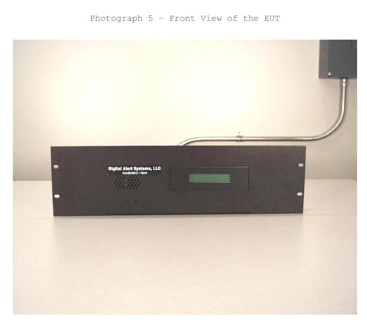
R8VDASDEC-1EN
Aug 19, 2004EAS ENCODER/DECODER
Equipment Class
EAD - Part 11 Emergency Alert Devices