RA9RA-7203VHF AM Receiver
Jotron AS
Click to zoom
Application Details
- Equipment Class
- CXX - Communications Rcvr for use w/ licensed Tx and CBs
- Date of Grant
- Jul 10, 2007
- Application Purpose
- Original Equipment
- Date of Application
- Jul 10, 2007
- Equipment Note
- VHF AM Receiver
- Frequency Range
- 118.00000000 - 137.00000000
- Company
- Jotron AS
- Country
- Norway
Documents & Files
Document Text
Text extracted from the exhibit documents filed with the FCC. Open a document above to read the original.
Users Manual
RA - 7203 123456 7 8 9 101112 1 DISPLAY 2 FbA (Function button A) 3 RS (Rotary switch) 4 SQUELCH LED 5 REMOTE LED 6 FRONT CONNECTOR 7 FbB (Function button B) 8 FbC (Function button C) 9 ON/OFF 10 ALARM LED11 STANDBY LED12 LOUDSPEAKER VHF Receiver RA - 7203 Front RJ45 connector Front Connector, RJ45 Name PIN Purpose SEL 1 TDO 2 Headset 3 RS232 4 RS232 Tx RS232 5 RS232 Rx TMS 6 +12VDC 7 +12 VDC to external equipment (10mA) GND 8 Common ground RA - 7203 Technical data, 1 of 4 Standards ; ICAO annex 10, EN300 676(AM, AM-MSK), EN301 841(VDL2 – Physical layer) Environmental: Temperature range -20 ° C to +55 ° C (operating) - 40 ° C to +70 ° C (storage) Humidity 90% @+40 ° C (non condensing) Shock Transport: IEC-721-3-2, Class 2M3 Vibration Transport: IEC-68-2-32, Class 2M3. IEC-68-2-6 EMC EN 301 489 – part 22 Weight: 1.7 kg Dimension: 71mm (14TE)(W) * 230mm(D) * 128mm (H) RA - 7203 Frequency response: 300-3400 Hz 350-2500 Hz Data ports: RS232, RS485, 100/10BaseT Protocol: (SNMP v.2) Simple Network Management RS232/RS485 Jotron proprietary BITE monitoring: VSWR, Voltages, Currents, Levels, Lock detect, Temperature, Out put power, Reflected power, a.o. Supply voltage: AC 115/230VAC +15/-10% / 50-60Hz Supply voltage, DC 21.6 - 31.2VDC negative ground MTBF: >10 years / unit MTTR: <30 minutes at lowest replaceable unit Technical data, 2 of 4 RA - 7203 Technical data, 3 of 4 Receiver AM 25kHz AM 8.33kHz Sensitivity analogue @1 μ V / 30% pd: 10dSINAD(CCITT) Adjacent channel rejection: >70dB >60dB Intermodulation (3 signal): >70 dBc IF bandwidth: +/- 11kHz +/-2.8kHz Image and IF frequency response: >110 dB Squelch operation: Adjustable 107dBm, 30dB S/N + carrier override Activation time <20ms Hysteresis <3dB Audio AGC: 30%-90%, <1dB variation Noise blanker: IF: Selectable ON/OFF Signal / Noise: >45dB on any output @100 μ V, 30% RA - 7203 Technical data, 4 of 4 AGC range: -107dBm to +5dBm AGC attach time: <50ms AGC decay time: <200ms Inband squelch signal: Configurable tones: 150-3400Hz Line output: 600 Ω , -36 - +7dBm @90% modulation Harmonic distortion: <3% @90% AM (line output) Crossmodulation: >85dB @ 100 kHz frequency offset Blocking: >100dB @1MHz offset, >110 dB out of band signals Dynamic range: >110dB Spurious response rejection: >90dB RA - 7203 Menus, 1 of 16 FbA RS FbB FbC NOTE! RS can be pressed and turned. The radio is controlled through an advanced menu system.The access for each menu is restricted by a user parameter. The System Operator can change a ll user parameters from SNMP, or from the menu using a hardware key. RA - 7203 Menus, 2 of 16 Userparameter: Name of menu: Access and restrictions: 1 System operator Full access to all parameters (R/W by System Operator) 2 Technician Access to some settings in RX menu system + bite (R/O) 3 Operators Access only to Volume, Frequency and memory storeand recall 4 Restricted Restricted to Volume, Squelch and memory recall There are four access user levels: RA - 7203Menus, 3 of 16 Push RS to switch in the operator menu When operated locally, the operator ha s full access to all facilities using the various controls at the front panel. RA - 7203 Menus, 4 of 16 Push menu button to enter MAIN MENU RA - 7203 Menus, 5 of 16 RA - 7203 Menus, 6 of 16 RA - 7203 Menus, 7 of 16 RX config subtree menu, 1 of 2 RA - 7203 Menus, 8 of 16 RX config subtree menu, 2 of 2 RA - 7203 Menus, 9 of 16 Interface config subtree menu, 1 of 2 RA - 7203 Menus, 10 of 16 Interface config subtree menu, 2 of 2 RA - 7203 Menus, 11 of 16 Bite system subtree, 1 of 2 RA - 7203 Menus, 12 of 16 Bite system subtree, 2 of 2 RA - 7203 Menus, 13 of 16 To maneuver in the menu systems, use the up-button FbA, the down-button FbB or (preferably) turn the RS. The different submenus are selected by pressing the rotary switch and turning up/down until the desired menu is reached. (FbA, FbB and FbC may be used as well)To return to previous menu, press RS (or FbC) when “ ,,,” is selected in the present menu.The RA-7203 will enter the Operator menu when turned “ON”. RA - 7203 Menus, 14 of 16 Operator menu, 1 of 3 PressRS Press RSPress RS Normal operating display with active squelch. Press Fb C to mute squelch. Normal operating display with no channels stored. Press Fb C to recall stored channels. Set loudspeaker volume by turning RS. Press FbC to mute loudspeaker. Set headset volume by turning RS. Press FbC to mute headset. Press RS RA - 7203 Menus, 15 of 16 Operator menu, 2 of 3 Press RS Press RSPress RS Set squelch level by turning RS. Press FbC to mute squelsh. See next page how to select frequency. Press FbC to store new frequency on specified channel. Select storing channel by turning RS. Select brightness level by turning RS. RA - 7203 Menus, 16 of 16 Operator menu, 3 of 3 Press FbA Press FbA Press FbC Select 8,33kHz steps by turning RS. For no changespress FbC.Select 100kHz steps by turning RS.Select 1MHz steps by turning RS.Press FbC to store new frequency and return. RA - 7203 Rear RJ45 connectors, 1 of 5 1234 5678 1 ANTENNA CONNECTOR 2 EARTH TAG 3 DC INPUT CONNECTOR 4 AC INPUT CONNECTOR 5 LAN CONNECTOR 6 AUX 1 CONNECTOR 7 AUX 2 CONNECTOR 8 REMOTE CONNECTOR RA - 7203 LAN interface connector Name PIN Purpose LAN_TXP 1 Tx data LAN_TXN 2 Tx data LAN_RXP 3 Rx data LAN_D3P 4 Optional LAN_D3N 5 Optional LAN_RXN 6 Rx data LAN_D4P 7 Optional LAN_D4N 8 Optional Rear RJ45 connectors, 2 of 5 RA - 7203 Aux 1 connector Name PIN Purpose ALARM_P 1 Alarm out – rele ALARM_N 2 Alarm out – rele Select_in_P 3 Select in – opto isolated RS232_S 4 RS232 Send data RS232_R 5 RS232 Receive data Select_in_N 6 Select in – opto isolated +12V 7 12V output to extequipment (D/O: 200mA) GND 8 Common ground Rear RJ45 connectors, 3 of 5 RA - 7203 AUX 2 connector Name PIN Purpose Squelch_out_P 1 Squelch out - opto isolated Squelch_out_N 2 Differential – opto isolated AGC_HILO_P 3 Hi / Lo depending on input signal(configurable) NC 4 NC 5 AGC_HILO_N 6 Differential – opto isolated AGC_ OUT 7 NC 8 Rear RJ45 connectors, 4 of 5 RA …
Text truncated - open the document above for the full version.
Cover Letter(s)
DATE 10th of May 2007 Nemko Canada Inc 303 River Road Ottawa, Ontario, Canada K1V 1H2 Attn: Director of Certification Authority to Act as Agent On our behalf, I appoint Nemko Comlab A/S, Gåsevikveien 8, Kjeller, Norway , to act as our agent in the preparation of this application for equipment certification. I certify that submitted documents properly describe the device or system for which equipment certification is sought. I also certify that each unit manufactured, imported or marketed, as defined in the Federal Communications Commission’s regulations will have affixed to it a label identical to that submitted for approval with this application. For instances where our authorized agent signs the application for certification on our behalf, I acknowledge that all responsibility for complying with the terms and conditions for certification, as specified by Nemko Canada Inc, still resides with Jotron AS, Kirkestien 1, PO Box 54, 3280 Tjodalyng, Norway. Dated this 10th of May 20 07 Agency agreement expiration date: 10 th May 2008 By: Eirik Storjordet Signature Printed Title: Certification Manager On behalf of : Jotron AS Telephone: +47 33139714
Cover Letter(s)
Tjodalyng: 06.07.2007 RE: CONFIDENTIALITY REQUEST FOR: FCC ID: RA9RA-7203 To whom it may concern: This letter serves as an official request for confidentiality under FCC rule section 0.459. We have requested that the following documents: Technical Manual, Maintenance and Repair Manual, Schematic Description, RA7203 blockdiagram.pdf document, RA7203 brief description.pdf document and Internal Photos required to be submitted with this application, to be withheld from public view. These documents are company property and must never get into the possession of Jotron AS competition. The sale and marketing of this equipment is limited to ground –to-air projects and the equipment is sold directly to these customers. The equipment is not available for our competitors to study. Sincerely, Eirik Storjordet Certification Manager [email protected] Tel. +47 33139714 Fax. +47 33126780 Attn: Reviewing Engineer Federal Communications Commission 7435 Oakland Mills Road Columbia, MD 21046 USA
Test Report
Nemko AS, Gaustadalléen 30, P.O.Box 73 Blindern, NO-0314 Oslo Norway T +47 22 96 03 30 F +47 22 96 05 50 Enterprise number NO974404532 Visiting address: Nemko Comlab, Gåsevikveien 8, P.O.Box 96, NO-2027 Kjeller Norway T +47 64 84 57 00 F +47 64 84 57 05 Test report no. : 71006/8 Item tested : RA-7203 Type of equipment : VHF Receiver FCC ID : RA9RA-7203 Client : Jotron AS FCC Part 15, subpart B (VHF receiver) 09 July 2007 Authorized by : ........................... ................... Egil Hauger Technical Verificator TEST REPORT FCC part 15B Project no.: 71006/8 Nemko Comlab, N-2027 Kjeller Page 2 (29) CONTENTS 1 GENERAL INFORMATION ............................................................................................................... 3 1.1 Testhouse Info ................................................................................................................................... 3 1.2 Client Information............................................................................................................................... 3 1.3 Manufacturer ( if other than client) ..................................................................................................... 3 2 TEST INFORMATION ....................................................................................................................... 4 2.1 Tested Item........................................................................................................................................ 4 2.2 Test Environment............................................................................................................................... 5 2.3 Test Period ........................................................................................................................................ 5 2.4 Test Engineer(s) ................................................................................................................................ 5 2.5 Test Equipment.................................................................................................................................. 5 2.6 Other Comments ............................................................................................................................... 5 3 TEST REPORT SUMMARY .............................................................................................................. 6 3.1 General .............................................................................................................................................. 6 3.2 Test Summary ................................................................................................................................... 7 3.3 Description of modification for Modification Filing .............................................................................. 7 3.4 Comments ......................................................................................................................................... 7 3.5 Family List Rational........................................................................................................................... 7 4 TEST RESULTS................................................................................................................................ 8 4.1 Power Line Conducted Emissions ..................................................................................................... 8 4.2 Spurious Emissions (Radiated)........................................................................................................ 10 4.3 Antenna power conduction limits for receivers................................................................................. 11 5 GRAPHS ......................................................................................................................................... 12 6 TEST SETUPS ................................................................................................................................ 28 6.1 Radiated Emissions Test ................................................................................................................. 28 6.2 Power Line Conducted Emissions Test ........................................................................................... 28 7 TEST EQUIPMENT USED .............................................................................................................. 29 TEST REPORT FCC part 15B Project no.: 71006/8 Nemko Comlab, N-2027 Kjeller Page 3 (29) 1 GENERAL INFORMATION 1.1 Testhouse Info Name : Nemko Comlab Address : Gåsevikveien 8, Box 96 N-2027 Kjeller, NORWAY Telephone : +47 64 84 57 00 Fax : +47 64 84 57 05 E-mail: [email protected] FCC test firm registration # : 994405 IC OATS registration # : 4443 Total Number of Pages: 29 1.2 Client Information Name : Jotron AS Address : P.O.Box 54, Kirkestian 1, 3280 Tjodalyng Telephone : +47 33 13 97 14 Fax : -- Contact: Name : Eirik Storjordet Telephone : +47 33 13 97 14 E-mail : [email protected] 1.3 Manufacturer ( if other than client) --„- TEST REPORT FCC part 15B Project no.: 71006/8 Nemko Comlab, N-2027 Kjeller Page 4 (29) 2 Test Information 2.1 Tested Item Name : Jotron Model/version : RX: RA-7203 Serial number : RX: 03 Hardware identity and/or version: RX: X84506:R0549, X82411:R0552 Software identity and/or version : RX: April 2007 Frequency Range : 118 – 136.975 MHz Tunable Bands : None Emission designator: 6K00A3E Number of Channels : 3 Operating Modes : RX (Simplex) Channel separation: 25kHz Type of Modulation : AM User Frequency Adjustment : Yes Rated maximum audio output: +10 dBm at 600 ohm line Type of Power Supply : 100 – 260 AC mains or 21 - 36VDC Antenna Connector : 50 Ohm N-connector Description of Test Item The Jotron TA 7600 series VHF radios are designed for ground to air communications on air port traffic control centers. The units are rack mounted. And the transmitter and receiver are separate units and have their own built in power supplies. Thes…
Text truncated - open the document above for the full version.
Test Setup Photos
FCC Part 15B Project no.: 71006/8 Page 1 of 1 Nemko Comlab, N-2007 Kjeller TEST SET-UP PHOTOS Conducted emission 150kHz – 30MHz , AC/DC mains Test set-up for Radiated emission 50 ohm termination
Contact Information
Applicant
Frank Loke(Certification Manager)
Technical Contact
Non-Technical Contact
Jotron ASBjorn Allum
[email protected]47 33139726
Test Firm
Nemko ASFrode Sveinsen
Technical Specifications
| # | Rule Parts | Frequency Range | Power Output |
|---|---|---|---|
| 1 | 15B | 118 MHz - 137 MHz | - |
Other Applications from Jotron AS

RA9RA-7203C
Jun 05, 2014VHF Receiver 156.300-162.000MHz for coast stations and offshore installations requiring high quality FM voice and digital selective calling (DSC)
Equipment Class
CXX - Communications Rcvr for use w/ licensed Tx and CBs
RA9TR-810
Apr 15, 2008VHF AM Transceiver
Equipment Class
TNB - Licensed Non-Broadcast Station Transmitter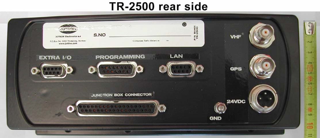
RA9TR2500
Jul 01, 2004Tron UAIS TR-2500
Equipment Class
AIS - Automatic Identification Systems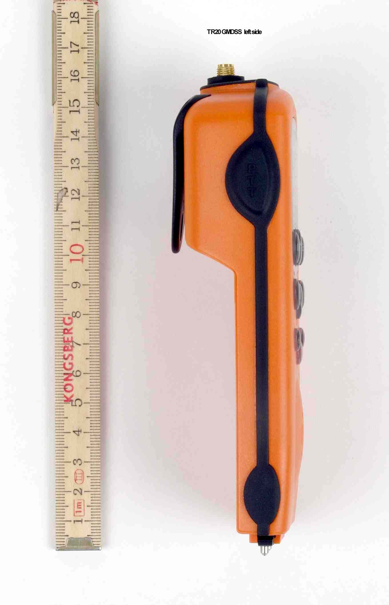
RA9TRONTR20GMDSS
Oct 02, 2003Tron TR20 GMDSS
Equipment Class
GHH - Part 80 VHF Hand Held Transmitter (GMDSS)