RAL-0101Tag Reader
EDiT iD Ltd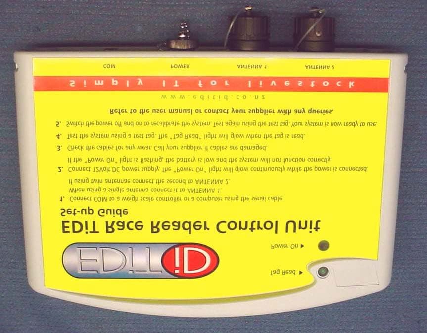
Click to zoom
Application Details
- Equipment Class
- DXX - Part 15 Low Power Communication Device Transmitter
- Date of Grant
- Jul 28, 2003
- Application Purpose
- Original Equipment
- Date of Application
- Jul 28, 2003
- Equipment Note
- Tag Reader
- Frequency Range
- 0.13420000 - 0.13420000
- Company
- EDiT iD Ltd
- Country
- New Zealand
Documents & Files
Document Text
Text extracted from the exhibit documents filed with the FCC. Open a document above to read the original.
Users Manual
1 Information to the User Read this document prior to installation! USA - Federal Communications Commission (FCC) This device complies with Part 15 of FCC Rules. Operation of the device is subject to the following two conditions (1) This device may not cause harmful interference, and (2) this device must accept any interference that may cause undesired operation. Caution This equipment has been designed, constructed, and tested for compliance with FCC Rules that regulate intentional readers. Any change or modification not expressly approved by electronic data manufacturing limited may void FCC certification and the user’s authority to operate this equipment. 2 EDiT Race Reader Control Unit Introduction The EDiT Race Reader Control Unit is part of the EDiT Race Reader System. It is designed to give hands-free reading and collection of data from NLIS approved animal electronic identification devices. No line of sight or restraint of animals is necessary. The reader "decodes" the signal received from the electronic identification device on the animal. The reader delivers the signal in a format that is compatible with EID- capable weigh scales or computer programs. The race reader control unit is designed solely for use with the EDiT Antenna. It is enclosed in a rugged waterproof and dustproof casing designed to withstand outdoor handling. Features “Power On” light Glows red when a 12V DC supply is attached. A flashing light indicates low voltage and the reader will not function correctly. COM connector POWER connector ANTENNA connectors “Tag Read” light Glows green for three seconds when a tag is read. 3 Power Supply The reader depends on a clean high quality 12V DC power supply to function correctly. A power supply of less than 12V DC will significantly affect performance. When the power supply is connected the "Power On" light will glow. When the voltage supply is not adequate the light will flash indicating that the power supply needs changing. The power connector is fitted with an inline fuse that protects the reader against inappropriate voltage fluctuations and incorrect battery terminal polarity. Communication Connector Use the 3m cable supplied to connect the reader to the weigh scale or computer. If the cable supplied is not long enough, an additional serial cable of up to 7m may be added without affecting performance. Accessories 1 x plastic mounting bracket with fittings 1 x Allflex ISO output test tag 1 x 3m power cable 1 x 3m communication cable Locating the Reader When in use the reader should always be mounted on the bracket provided. Securely mount the control unit bracket in a convenient place so it; • does not to interfere with animal and operator movements • is within reach of the COM, POWER and ANTENNA cables • allows the power cable to be connected with the battery positioned in a suitable location • the "Tag Read” and “Power On” lights are clearly visible. Cable Management Route cables where they cannot be damaged by animals, or crushed and stretched by moving parts such as gates or headbail mechanisms. If in doubt place cables inside protective hose or piping. Secure using cable ties. Dust caps should be screwed in place when any of the connectors are not attached to external cables. Do NOT connect the reader to a battery in a running vehicle or an automotive battery charger. The voltage and current supplied may damage the reader and would void the warranty. 4 Getting Started Make sure that the cables are securely connected in the following order. COM Connect to weigh scale indicator or computer ANTENNA If using a single antenna connect to ANTENNA 1. Only use ANTENNA 2 if a dual antenna arrangement is installed. POWER Connect to a fully charged 12V DC battery, i.e. Connect the RED clip to the POSITIVE terminal. Connect the BLACK clip to the NEGATIVE terminal. If the clips are connected incorrectly the inline fuse will blow and will have to be replaced before proceeding. Do not change the fuse rating (1.6 amp). The “Power On” indicator will glow red indicating that sufficient voltage is being supplied. The light will flash if there is insufficient voltage. The reader will not function correctly and the battery needs to be changed before proceeding. Check that the reader is functioning correctly. Once power and antenna cables are correctly attached the system is ready to read tags. Bring the test tag provided into the area directly in front of the antenna (see antenna instructions for expected read area diagram). The green light will glow when the tag is read successfully. The light stays on for three seconds after a successful read. If a weigh scale indicator or computer is attached and correctly set-up, (see the instruction manual of the scales indicator or computer) the display will indicate the number of the identification device. If the tag is not read successfully when introduced into the read area (green light is not glowing), disconnect the power for a few moments and then try again. This will allow the system to recalibrate. BEFORE connecting the power cable set the crush up exactly as you expect it to be when tagged animals are to be read: headbail closed, inspection gates as required etc. 5 Any time that the antenna is moved or the crush set-up is changed the reader needs to be recalibrated. Cleaning The reader is designed to withstand dust and water. Clean using household detergents and cold running water. Do not use abrasive cleaners or solvents as these may damage the reader and void the warranty. 6 The EDiT Antenna Introduction The EDiT Antenna is part of the EDiT Race Reader System. The race reader system identifies and reads electronic devices on individual animals, allowing for accurate traceability and management of stock. The EDiT Race Reader Control Unit powers the antenna and transfers the data received from electronic eartags into a weigh scale indicator or a computer. Robust construction materials and design allow the antenna to be fitted on the …
Text truncated - open the document above for the full version.
Block Diagram
Electronic Data Manufacturing Ltd. 1 of 1 pages Block diagram for the EDiT iD Race Reader Transmitter Clock Receiver Microcontroller Power Regulator RS232 Interface Antenna External to Race Reader 17.1776 MHz 12V DC battery PC Slave controller 8.8 MHz
Cover Letter(s)
Response to TCB Findings 1. Test data is needed when the device operates with 2 antennas connected and compliance should be demonstrated. The user’s should also be instructed in the manual about the installation of the 2 antenna configuration the way it will be tested for compliance. Response: Additional test data for the 2 antenna configuration has been supplied. User’s manual has now instructions on 2 antenna installation to ensure compliance. 2. The label should include the compliance statement required by 15.19(a)(3). Please provide new label sample. Response: Supplied. Please see the new label sample.
External Photos
EMC Technologies (NZ) Ltd Test Report No 30326.3 Report date: 11 June 2003 __________________________________________________________________________________________________________________________________________________________________________________ EMC Technologies (NZ) Ltd Telephone: +64 9 360 0862 Fax: +64 9 360 0861 STREET ADDRESS - 47 MacKelvie Street, Grey Lynn, Auckland, New ZealandE-mail: [email protected] POSTAL ADDRESS - PO Box 68 307, Newton, Auckland, New ZealandWeb Site: www.emctech.com.au Page 12 of 13This report may not be reproduced except in full 9.PHOTOGRAPH (S) EMC Technologies (NZ) Ltd Test Report No 30326.3 Report date: 11 June 2003 __________________________________________________________________________________________________________________________________________________________________________________ EMC Technologies (NZ) Ltd Telephone: +64 9 360 0862 Fax: +64 9 360 0861 STREET ADDRESS - 47 MacKelvie Street, Grey Lynn, Auckland, New ZealandE-mail: [email protected] POSTAL ADDRESS - PO Box 68 307, Newton, Auckland, New ZealandWeb Site: www.emctech.com.au Page 13 of 13This report may not be reproduced except in full
ID Label/Location Info
EMC Technologies (NZ) Ltd Test Report No 30326.3a Report date: 18 July 2003 __________________________________________________________________________________________________________________________________________________________________________________ EMC Technologies (NZ) Ltd Telephone: +64 9 360 0862 Fax: +64 9 360 0861 STREET ADDRESS - 47 MacKelvie Street, Grey Lynn, Auckland, New Zealand E-mail: [email protected] POSTAL ADDRESS - PO Box 68 307, Newton, Auckland, New Zealand Web Site: www.emctech.com.au Page 17 of 20 This report may not be reproduced except in full Label Details
ID Label/Location Info
Drawing No.: Title: Sheet No.: Part No.: D ate: Authoris ed: Revision History: of 103, Carbine Road Mt. Well ington Auckland, New Zeala nd +6 4 9 574 3100 © edml 2003 NZ Rev.:Description:Date:By: Dimensions in mm unless otherwise specified Tolerances +/- 0.5mm unless otherwise specified 55 mm 2 9 m m 11 0101-2063-30 Reader unit FCC Compliance label 0 10 1-20 63-0 0 21/0 7/20 0 3 OOriginal21/07/2003SL Scale: 2 : 1 RFID Reader unit Model No.: 0101-0000-00 This device complies with Part 15 of the FCC Rules. Operation is subject to the following conditions: (1) This device may not cause harmful interference, and (2) this device must accept any interference received, including interference that may cause undesired operation FCC ID: RAL-0101 Notes: Label outline, dimensions and centrelines shown Brand: Brady Part: THT-17-483-3 Label colour: White Print colour: Black Label material: Polyester Font type: Tahoma (or similar) Font size: to suit FCC compliance text must be at least 1mm high
Internal Photos
Internal Photographs
Operational Description
Electronic Data Manufacturing Ltd. 1 of 2 pages Description of the EDiT iD Race Reader 1 Introduction The EDiT iD race reader can securely read and identify RFID tags applied to moving animals. These tags may be either FDX or HDX ISO 11784 / ISO 11785 compliant tags, or tags known as industrial tags. Although the Race reader control unit and the antenna are separate units, they always operate together. The antenna is the load driven by the control unit. The race reader control unit is designed solely for the use with the EDiT antenna. The control unit activates the interrogation field of RFID tags via an antenna, receives and decodes the response and also transfers the received data into a weigh scale indicator or a computer if desired by the operator. The ISO tag is available from a number of third party sources. 2 Control unit The control unit circuit consists of the following: ∑ Transmitter with auto tune capability (transmits on 134.2 kHz) ∑ Transmitted signal generator (gated carrier) ∑ HDX receiver and discriminator ∑ FDX receiver and demodulator ∑ Decoder and control circuitry ∑ Regulated power supply EDiT iD Race Reader Control unit Antenna ISO Tag PC, Weigh scale indicator Figure 1: EDiT iD race reader diagram Electronic Data Manufacturing Ltd. 2 of 2 pages ∑ External interface and interconnections to supporting circuitry o 1 RSR232 connection for communication to PC and third party equipment (e.g. weigh scale indicator) o 2 antenna connections o 12VDC power connection from battery The control unit is powered using an external lead acid battery in an environment where AC mains would not be available. 3 EDiT iD Antenna The EDiT iD antenna is 840 x 640 x 25 mm in size. During operation, the antenna is connected to port ANTENNA 1 of the control unit. The antenna connectors on the control unit would be classed as being unique and cannot be used with a standard antenna jack or electrical connector. The EDiT iD antenna is strictly speaking an induction loop with two turns of centre- tapped wire. The centre-tap of the coil is connected to ground. The antenna is therefore balanced. Capacitors are connected in parallel across the coil to achieve resonance. The antenna resonates at 134.2 kHz.
Parts List/Tune Up Info
Electronic Data Manufacturing Ltd. 1 PART LIST MC MC –– Micro Controller components Micro Controller components PS – Power supply components TX – Transmitter circuit comps. AT – Antenna tuning comps. ALL – Components available to all boards. FDX FDX –– Full Duplex circuit components Full Duplex circuit components HDX – Half duplex circuit components Section Qty Part Category Description / Value / Specifier Status Circuit Designator PS 1 Fuse, 5A, fast, PCB mount 5A fast Firm F1 PS 1 Ind, coil, common mode choke 60uH 3.3A choke Firm L8 PS 1 Cap, SMT, 0.1μF, 0603, 50V, 20%, ceramic 100n 50V Firm C60 PS 2 Cap, THT, 1000μF, radial, 25V, 10mm, 10%, electrolytic 1000uF Firm C90,91 PS 1 Tran, NPN BC847 Firm Q14 PS 1 IC, THT, Regulator, 1A adjustable, automotive LM2941CT Firm U13 PS 1 Heatsink Heatsink Firm HS1 PS 2 Res, SMT, 1K, 0603, 5%, carbon film 1K Firm R71,72 PS 1 Res, SMT, 6K8, 0603, 5%, carbon film 6K8 Firm R70 PS 1 Res, SMT, 33K, 0603, 5%, carbon film 33K Firm R68 TX 1 Res, SMT, 2R2, 0603, 5% 2R2 Firm R75 PS 1 Dio, power, 1A Si PRLL4002 Firm Z2 TX 2 Res, SMT, 0R68, 2512, 5%, carbon film 0R68 Firm R63,66 TX 2 Res, SMT, 10R, 0603, 5% 10R Firm R64,67 TX 4 Res, SMT, 1K, 0603, 5% 1K Firm R62,65,30, 42 TX 4 Cap, SMT, 0.01μF, 0603, 16V, 20%, ceramic 10n Firm C73,74, C49, C50 TX 2 Cap, THT, 8200pF, axial, 100V, 10%, polyester 8n2 N/C C80,92 TX 2 Cap, SMT, 0.1μF, 0603, 16V, 20%, ceramic 100n Firm C58,59 TX 1 Cap, THT, 1000μ, radial, 25V, 10mm, 10%, electrolytic 1000uF Firm C89 TX 2 Tran, SMT, MOSFET NDT3055L Firm Q10,11 TX 1 IC, THT, 1.5A DUAL MOSFET DRIVER TC4428(COA/EOA = TEMP RANGE DIFF) Firm U12 TX 4 Dio, SMT, Signal, BAS16, SOT-23 BAS16 Firm D8,D9,D7,D2 Electronic Data Manufacturing Ltd. 2 AT 8 Tran, THT, MOSFET IRF740 Firm Q2,3,4,5,6,7,8,9 AT 1 Cap, THT, 470pF, axial, 250V, 5%, polypropylene 470p Firm C85 AT 1 Cap, THT, 1000pF, axial, 250V, 5%, polypropylene 1n KT347 Firm C83 AT 2 Cap, SMT, 1500pF, 0603, 50V, 20%, ceramic 1n5 50V Firm C87,88 AT 1 Cap, THT, 2200pF, axial, 250V, 5%, polypropylene 2n2 KT347 Firm C82 AT 1 Cap, THT, 4700pF, axial, 250V, 5%, polypropylene 4n7 KT347 Firm C81 AT 1 Cap, THT, 0.01μF, axial, 250V, 5%, polypropylene 10n Firm C65 AT 6 Cap, SMT, 0.01μF, 0603, 50V, 20%, ceramic 10n 50V Firm C64,66,67,68,69,70 AT 1 Cap, THT, 0.01μF, axial, 250V, 10%, polypropylene 10n Firm C79 AT 1 Cap, THT, 0.022μF, axial, 250V, 5%, polypropylene 22n , MKP 479 Firm C78 AT 1 Cap, THT, 0.047μF, axial, 250V, 5%, polypropylene 47nF Firm C57 AT 1 Cap, THT, 0.1μF, axial, 250V, 5%, polypropylene 100nF N/C C86 AT 2 Res, THT, 10R, axial, 10mm, 5%, 0.25W 10R Firm R60,61 AT 1 Res, THT, 100R, axial, 15mm, 5%, 0.5W 100R Firm R50 AT 8 Res, THT, 47K, axial, 10mm, 5%, 0.25W, 250V 47K Firm R51,52,53,54,55,56,57,58 AT 2 Cap, THT, ???, axial, N/C C71,72 HDX 1 Res, SMT, 470R, 0603, 5% 470R Firm R1 HDX 4 Res, SMT, 1K, 0603, 5% 1K Firm R17,21,27,34 HDX 1 Res, SMT, 33K, 0603, 5% 33K Firm R59 HDX 4 Res, SMT, 330K, 0603, 5% 330K Firm R45,46,47,48 HDX 2 Res, SMT, 470K, 0603, 5% 470K Firm R73,74 HDX 1 Res, SMT, 5% ?? N/C R44 HDX 1 Cap, SMT, 68pF, 0603, 16V, 20%, ceramic 68p Firm C42 HDX 3 Cap, SMT, 68pF, 0603, 16V, 20%, ceramic 68p N/C C43,44,45 HDX 3 Cap, SMT, 150pF, 0603, 16V, 20%, ceramic 150p Firm C46,47,48 HDX 1 Cap, THT, 820pF, axial, 250V, 1%, 5mm, polystyrene 820pF Firm C40 Electronic Data Manufacturing Ltd. 3 HDX 1 Cap, THT, 680pF, axial, 160V, 2%, 5mm, polystyrene 680pF Firm C77 HDX 1 Cap, SMT, 180pF, 0603, 16V, 20%, ceramic 180p Firm C41 HDX 1 Cap, THT, 1500pF, axial, 160V, 5mm, 2% polystyrene 1500p Firm C76 HDX 1 Cap, SMT, 0.01μF, 0603, 50V, 20%, ceramic 10n 50V Firm C63 HDX 1 Cap, THT, 1500pF, radial, 100V, 5mm, 5%, polypropylene 1500p Firm C75 HDX 1 Cap, SMT, 0.1μF, 0603, 16V, 10% ceramic 100n 250V Firm C39 HDX 1 Cap, SMT, 10μ, TANTB, 16V, 20%, tantalum 10u + Firm C51 HDX 2 Ind, coil, RF TOKO-10EZ Firm L6,7 HDX 2 Dio, Double BAV23 Firm D4,5 HDX 1 Dio, Double BAV99 Firm D3 HDX 1 IC, Hex inverter chip HEF4069UBT Firm U2 FDX 1 Res, SMT, 100R, 0603, 5% 100R Firm R22 FDX 1 Res, SMT, 2K2, 0603, 5% 2K2 Firm R28 FDX 1 Res, SMT, 3K3, 0603, 5% 3K3 Firm R19 FDX 3 Res, SMT, 4K7, 0603, 5% 4K7 Firm R9,32,31 FDX 1 Res, SMT, 15K, 0603, 5% 15K Firm R25 FDX 1 Res, SMT, 22K, 0603, 5% 22K Firm R12 FDX 1 Res, SMT, 33K, 0603, 5% 33K Firm R29 FDX 1 Res, SMT, 47K, 0603, 5% 47K Firm R8 FDX 3 Res, SMT, 100K, 0603, 5% 100K Firm R33,35,41 FDX 2 Res, SMT, 220K, 0603, 5% 220K Firm R2,40 FDX 1 Res, SMT, 10K, 0603, 5% 10K Firm R24 FDX 1 Cap, SMT, 68pF, 0603, 16V, 20%, ceramic 68p Firm C14 FDX 1 Cap, SMT, 180pF, 0603, 16V, 20%, ceramic 180p Firm C26 FDX 2 Cap, SMT, 4700pF, 0603, 16V, 20%, ceramic 4n7 Firm C13,17 FDX 2 Cap, SMT, 0.01μF, 0603, 16V, 20%, ceramic 10n Firm C30,36 Electronic Data Manufacturing Ltd. 4 FDX 1 Cap, THT, 0.01μF, axial, 250V, 10%, 7.5mm, met. polyester 10n Firm C8 FDX 1 Cap, THT, 0.1μF, axial, 250V, 10%, 5mm, met. polyester 100n Firm C7 FDX 1 Cap, SMT, 0.22μF, 0603, 16V, 20%, ceramic 220n Firm C29 FDX 2 Cap, SMT, 1μ, 1206, 16V, 20%, ceramic 1u Firm C16,31 FDX 1 Cap, SMT, 4μ7, 1206, 16V, 20%, ceramic 4u7 Firm C22 FDX 2 Cap, SMT, 100μ, TANTD, 10V, 20%, tantalum 100u Firm C18,32 FDX 4 Cap, SMT, ????, 0603, 16V, 20%, ceramic ?? N/C C12,15,19,24 FDX 2 Cap, SMT, ???, 0603, 16V, 20%, ceramic ?? N/C C21, C27 FDX 1 Dio Schottky BAR43 Firm D6 FDX 1 Tran, SMT, FET BSS138 Firm Q1 FDX 2 IC, Dual OpAmp MC33077 Firm U4,8 MC 4 Res, SMT, 330R, 0603, 5% 330R Firm R5,6,11,18 MC 5 Res, SMT, 1K, 0603, 5% 1K Firm R3,7,23,37,43 MC 2 Res, SMT, 3K3, 0603, 5% 3K3 Firm R20,26 MC 1 Res, SMT, 4K7, 0603, 5% 4K7 Firm R10 MC 2 Res, SMT, 100K, 0603, 5% 100K Firm R15, R69 MC 1 Res, SMT, 220K, 0603, 5% 220K Firm R14 MC 1 Res, SMT, 1M, 0603, 5% 1M Firm R38 MC Res, SMT, 5% ?? N/C R36 MC 2 Cap, SMT, 27pF, 0603, 16V, 20%, ceramic 27p Firm C33,35 MC 18 Cap, SMT, 0.1μF, 0603, 16V, 20%, ceramic 100n Firm C1,2,3,4,11,20,23,25,28,34,37,38,52,53,54,55,56 MC 1 Cap, SMT, 10μ, TANTB, 16V, 20%, tantalum 10u Firm C10 MC Cap, SMT, ????, 0603, 16V, 20%, ceramic…
Text truncated - open the document above for the full version.
Test Report
EMC Technologies (NZ) Ltd Test Report No 30326.3b Report date: 18 July 2003 __________________________________________________________________________________________________________________________________________________________________________________ EMC Technologies (NZ) Ltd Telephone: +64 9 360 0862 Fax: +64 9 360 0861 STREET ADDRESS - 47 MacKelvie Street, Grey Lynn, Auckland, New Zealand E-mail: [email protected] POSTAL ADDRESS - PO Box 68 307, Newton, Auckland, New Zealand Web Site: www.emctech.com.au Page 1 of 24 This report may not be reproduced except in full TEST REPORT EDiT iD 0101-0000-00 Long Range Race Reader Interface tested to 47 Code of Federal Regulations Part 15 - Radio Frequency Devices Subpart C – Intentional Radiators for Electronic Data Manufacturing Ltd This Test Report is issued with the authority of: ______________________________________ Andrew Cutler - General Manager Prepared By: ______________________________________ Karen Miller - Office Administrator EMC Technologies (NZ) Ltd Test Report No 30326.3b Report date: 18 July 2003 __________________________________________________________________________________________________________________________________________________________________________________ EMC Technologies (NZ) Ltd Telephone: +64 9 360 0862 Fax: +64 9 360 0861 STREET ADDRESS - 47 MacKelvie Street, Grey Lynn, Auckland, New Zealand E-mail: [email protected] POSTAL ADDRESS - PO Box 68 307, Newton, Auckland, New Zealand Web Site: www.emctech.com.au Page 2 of 24 This report may not be reproduced except in full Table of Contents 1. STATEMENT OF COMPLIANCE 3 2. RESULTS SUMMARY 3 3. INTRODUCTION 4 4. CLIENT INFORMATION 4 5. DESCRIPTION OF TEST SAMPLE 5 6. RESULTS 5 7. TEST EQUIPMENT USED 15 8. ACCREDITATIONS 15 9. PHOTOGRAPH (S) 16 EMC Technologies (NZ) Ltd Test Report No 30326.3b Report date: 18 July 2003 __________________________________________________________________________________________________________________________________________________________________________________ EMC Technologies (NZ) Ltd Telephone: +64 9 360 0862 Fax: +64 9 360 0861 STREET ADDRESS - 47 MacKelvie Street, Grey Lynn, Auckland, New Zealand E-mail: [email protected] POSTAL ADDRESS - PO Box 68 307, Newton, Auckland, New Zealand Web Site: www.emctech.com.au Page 3 of 24 This report may not be reproduced except in full 1. STATEMENT OF COMPLIANCE The EDiT iD 0101-0000-00 Long Range Race Reader Interface complies with FCC Part 15 Subpart C as an Intentional Radiator when the methods, as described in ANSI C63.4 - 1992, are applied. 2. RESULTS SUMMARY Clause Parameter Result 15.201 Equipment authorisation requirement Certification required. 15.203 Antenna requirement Complies. Antenna connector unique. 15.204 External PA and antenna modifications Not applicable. No external devices. 15.205 Restricted bands of operation Complies. Device transmits on 134.2 kHz 15.207 Conducted limits Complies with a 21.96 dB margin at 17.180 MHz (Average) when using 2 antennas. 15.209 Radiated emission limits - Fundamental Complies with a 3.7 dB margin when using 2 antennas. 15.209 Radiated emission limits - Spurious emissions <30 MHz Complies with a 10.9 dB margin at 537 and 1208 kHz. 15.209 Radiated emission limits – Spurious emissions >30 MHz Complies with a 12.9 margin at 377.955 MHz. EMC Technologies (NZ) Ltd Test Report No 30326.3b Report date: 18 July 2003 __________________________________________________________________________________________________________________________________________________________________________________ EMC Technologies (NZ) Ltd Telephone: +64 9 360 0862 Fax: +64 9 360 0861 STREET ADDRESS - 47 MacKelvie Street, Grey Lynn, Auckland, New Zealand E-mail: [email protected] POSTAL ADDRESS - PO Box 68 307, Newton, Auckland, New Zealand Web Site: www.emctech.com.au Page 4 of 24 This report may not be reproduced except in full 3. INTRODUCTION This report describes the tests and measurements performed on the EDiT iD 0101- 0000-00 Long Range Race Reader Interface for the purpose of determining compliance with the specification. The client selected the test sample. This report relates only to the sample tested. This report contains no corrections or erasures. Measurement uncertainties with statistical confidence intervals of 95% are shown below test results. Both Class A and Class B uncertainties have been accounted for, as well as influence uncertainties where appropriate. This report has been issued in addition to test report number 30326.3a and contains additional test results relating to tests carried out with 2 antennas attached. 4. CLIENT INFORMATION Company Name Electronic Data Manufacturing Ltd Address PO Box 11017 Ellerslie City Auckland Country New Zealand Contact Ms Ursula Grill EMC Technologies (NZ) Ltd Test Report No 30326.3b Report date: 18 July 2003 __________________________________________________________________________________________________________________________________________________________________________________ EMC Technologies (NZ) Ltd Telephone: +64 9 360 0862 Fax: +64 9 360 0861 STREET ADDRESS - 47 MacKelvie Street, Grey Lynn, Auckland, New Zealand E-mail: [email protected] POSTAL ADDRESS - PO Box 68 307, Newton, Auckland, New Zealand Web Site: www.emctech.com.au Page 5 of 24 This report may not be reproduced except in full 5. DESCRIPTION OF TEST SAMPLE Brand Name EDiT iD Model Number 0101-0000-00 Product Long Range Race Reader Interface Manufacturer Electronic Data Manufacturing Ltd Country of Origin New Zealand Serial Number OD-062-005 6. RESULTS Standard The sample was tested in accordance with 47 CFR Part 15 Subpart C. Methods and Procedures The measurement methods and procedures as described in ANSI C63.4 - 1992 were used. Section 15.201: Equipment authorisation requirement Certification as detailed in Subpart J of Part 2 is required for this device. Section 15.203: Antenna requirement As can be seen from the attached photographs…
Text truncated - open the document above for the full version.
Test Setup Photos
Radiated emissions test set up
Contact Information
Applicant
Michael Uganecz(Engineering Manager)
Test Firm
EMC Technologies NZ Ltd.Andrew Cutler
Technical Specifications
| # | Rule Parts | Frequency Range | Power Output |
|---|---|---|---|
| 1 | 15C | 0.1342 MHz - 0.1342 MHz | - |
Other Applications from EDiT iD Ltd

RAL-0403
Sep 18, 2006LOW FREQUENCY RFID TRANSCEIVER
Equipment Class
DCD - Part 15 Low Power Transmitter Below 1705 kHz