RAN90164THERMOSTAT TRANSCEIVER
AED Electronics Inc.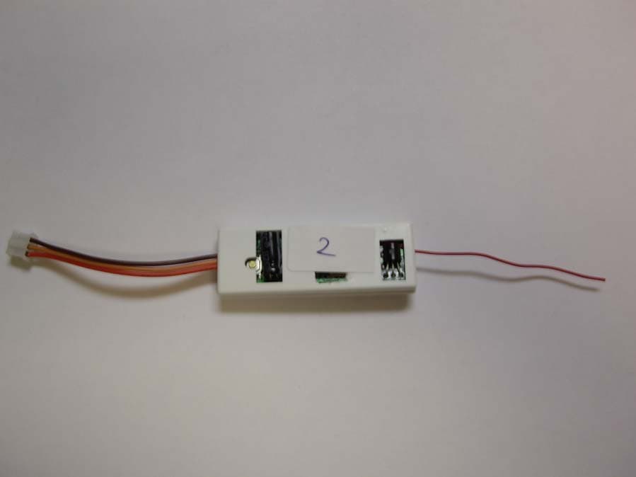
Click to zoom
Application Details
- Equipment Class
- DSS - Part 15 Spread Spectrum Transmitter
- Date of Grant
- Aug 30, 2006
- Application Purpose
- Original Equipment
- Date of Application
- Aug 30, 2006
- Equipment Note
- THERMOSTAT TRANSCEIVER
- Frequency Range
- 903.50000000 - 914.90000000
- Company
- AED Electronics Inc.
- Country
- Canada
Documents & Files
Document Text
Text extracted from the exhibit documents filed with the FCC. Open a document above to read the original.
Users Manual
Outdoor Wireless Temperature Transmitter and Receiver Kit Installation Instructions 1.Remove the 4screws located at the back of the Transmitter and install the 2AA batteries included. The LED will flash on the transmitter periodically. Screw the antenna into the top. 2.Install the receiver by simply removing the top cover of the thermostat, plug the receiver into the white connector located to the left of the screw terminals. (A) 3.Place the antenna wire into the 4th vent as shown (B). Clip the receiver into the 2nd vent (C). 4.Press the “reset” button on the receiver module for 10seconds to activate the transmitter and receiver. The outdoor temperature will appear on your thermostat within 5minutes. (D) 5.Position your Outdoor Transmitter in a permanent location. You must place the Outdoor Transmitter in an area that is sheltered from the elements. Suggestions include under the eaves, an upper window frame. 6.Finally, on your thermostat, ensure that the dot to the right of the temperature (E) flashes approximately every 15seconds. Caution: If there is no temperature on the thermostat - press the “reset” button on the receiver module again for 10 seconds to activate the transmitter and receiver. Note: If a replacement transmitter is required this procedure must be followed to initialize the transmitter/receiver. Your kit includes: Outdoor Wireless Temperature Transmitter + Antenna + Receiver Module + 2Batteries This convenient feature provides you the outdoor temperature right on your thermostat. BCDA E Obtaining Warranty Service Customer must contact and return product to a local product dealer or installer within the applicable warranty period to obtain warranty serv- ice. Dated proof of original purchase will be required Hardware The Manufacturer warrants the original end user (“Customer”) that new branded products will be free from defects in workmanship and materi- als, under normal use, for two (2) years from the original purchase date. Software The Manufacturer warrants to Customer that the thermostat software will perform in substantial conformance to its program specifications for a period of two (2) years from the date of the original purchase. Exclusions This warranty excludes (1) physical damage to the surface of the product, including cracks or scratches on the touch-screen or outside casing; (2) damage caused by misuse, neglect, improper installation, unauthorized attempts to open, repair, or modify the product, or any other cause beyond the range of intended use; (3) damage caused by accident, fire, power changes, other hazard, or Acts of God; or (4) use of the product with any device if such device causes the problem. Exclusive Remedies Should a covered defect occur during the warranty period and Customer notifies The Manufacturer, Customer’s sole and exclusive remedy will be, at The Manufacturer’s sole option and expense, to repair or replace the product. Replacement products or parts may be new or reconditioned or a comparable version of the defective item. The Manufacturer warrants any replaced product or part for a period of ninety (90) days from shipment, or through the end of the original warranty, whichever is longer. Warranty Exclusive THE FORGOING WARRANTIES AND REMEDIES ARE EXCLUSIVE AND IN LIEU OF ALL OTHER WARRANTIES, EXPRESS OR IMPLIED, INCLUDING WARRANTIES OF MERCHANTABILITY, FITNESS FOR A PARTICULAR PURPOSE, CORRESPONDENCE WITH DESCRIPTION, AND NON- INFRINGEMENT, ALL OF WHICH ARE EXPRESSLY DISCLAIMED BY THE MANUFACTURER AND ITS SUPPLIERS. Disclaimer NEITHER THE MANUFACTURER NOR ITS SUPPLIERS SHALL BE LIABLE FOR INCIDENTAL, CON- SEQUENTIAL, INDIRECT, SPECIAL, OR PUNITIVE DAMAGES OF ANY KIND, OR FINANCIAL LOSS ARISING OUT OF OR IN CONNECTION WITH THE SALE OR USE OF THIS PRODUCT, WHETHER BASED IN CONTRACT, TORT (INCLUDING NEGLIGENCE) OR ANY OTHER THEORY, EVEN IF THE MANUFACTURER HAS BEEN ADVISED OF THE POSSIBILITY OF SUCH DAMAGES. THE MANU- FACTURER’S ENTIRE LIABILITY SHALL BE LIMITED TO REPLACEMENT OR REPAIR OF THE PRODUCT. FCC Statement THIS DEVICE COMPLIES WITH PART15OF THE FCC RULES. OPERATION IS SUBJECT TO THE FOLLOWING TWO CONDITIONS: (1) THIS DEVICE MAY NOT CAUSE HARMFUL INTERFERENCE, AND (2) THIS DEVICE MUST ACCEPT ANY INTERFERENCE RECEIVED, INCLUDING INTERFERENCE THAT MAY CAUSE UNDESIRED OPERATION. NOTE: THE MANUFACTURER IS NOT RESPONSIBLE FOR ANY RADIO OR TV INTERFERENCE CAUSED BY UNAUTHORIZED MODIFICATIONS TO THIS EQUIPMENT. SUCH MODIFICATIONS COULD VOID THE USER’S AUTHORITY TO OPERATE THE EQUIPMENT. THIS DEVICE HAS BEEN DESIGNED TO OPERATE WITH THE INCLUDED ANTENNA, AND HAVING A MAXIMUM GAIN OF 0DBD. ANTENNAS NOT INCLUDED IN THIS LIST OR HAV- ING A GAIN GREATER THAN 0DB ARE STRICTLY PROHIBITED FOR USE WITH THIS DEVICE. THE REQUIRED ANTENNA IMPEDANCE IS 52OHMS. US PATENT 6,902,117
Cover Letter(s)
AED ELECTRONICS, INC. June 7 , 2006 Please find below the list of Model Numbers of the Thermostat Transceiver and the corresponding Temperature Transceiver, under the FCC RAN 90064. Thermostat Transceiver Temperature Transceiver Model P286-1200 P286-0001 Model P286-1300 P286-0001 Model P286-1400 P286-0001 Model P286-1500 P286-0001 Model P286-1600 P286-0001 Model P286-1700 P286-0001/P286-0001 Model P286-1800 P286-0002 Model P286-1900 P286-0002 Model P286-2000 P286-0002 Thermostat Transceiver Temperature Transceiver Model TS21 TS01 Model TS32 TS01 Model TS32H TS01 Model TS21/2W TS01 Model TS23 TS01 Model TS33 TS02 Model TS24 TS02 Model TS24 TS02 Thermostat Transceiver Temperature Transceiver Model CT03TS21 915964 Model CT03TS32 915964 Model CT03TS32H 915964 Model CT03TS32/2 915964 Model CT03TS33 915964 Model CT03TS34 915965 Model CT03TS35 915965 Model CT03TS36 915965 Sincerely, Howard Rosen President AED Electronics, Inc. 5758 Royalmount Avenue, Montreal, Quebec, Canada H4P 1K5 Tel.:(514) 737-9332 Fax:(514) 737-0922
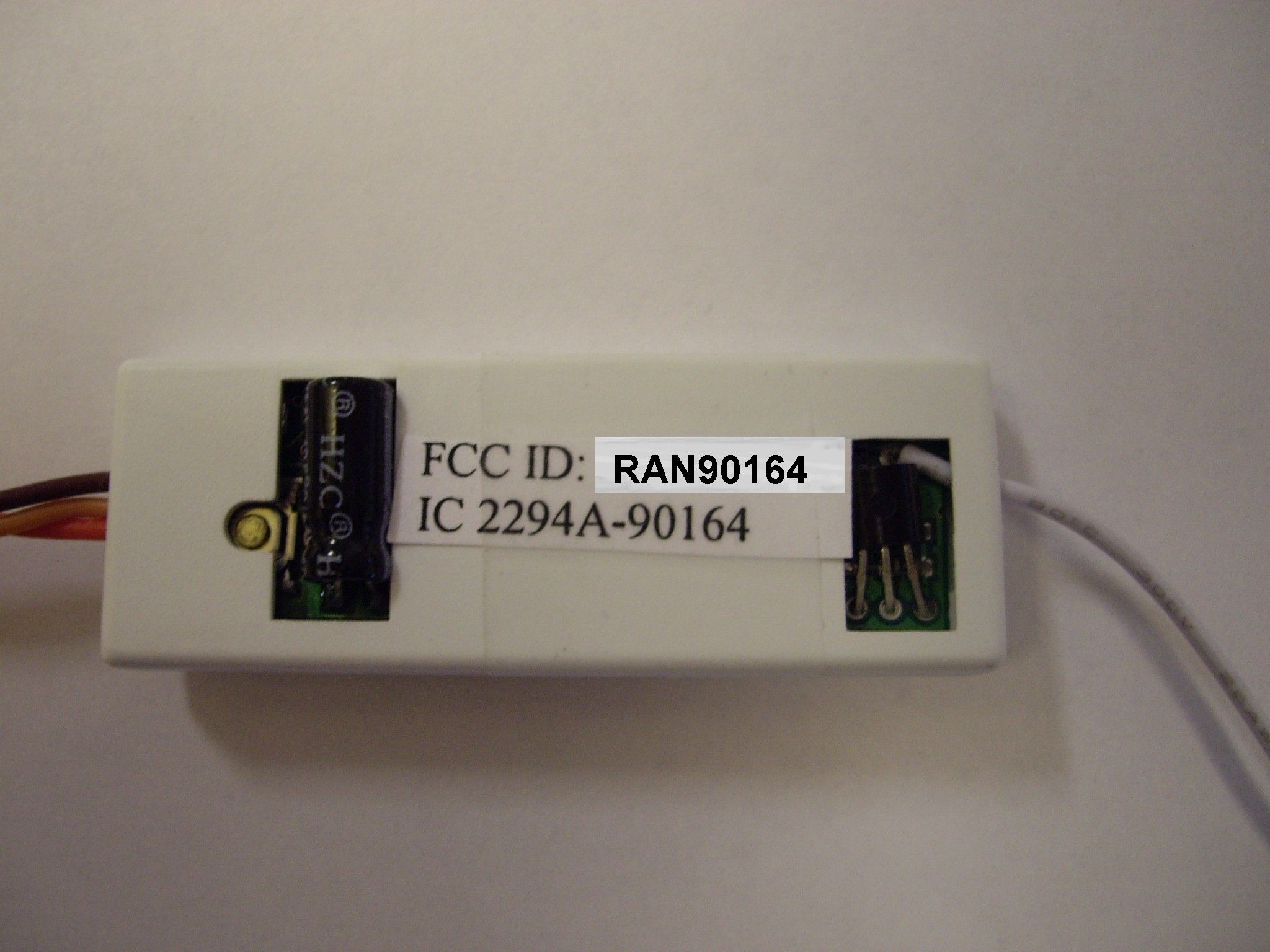
External Photos
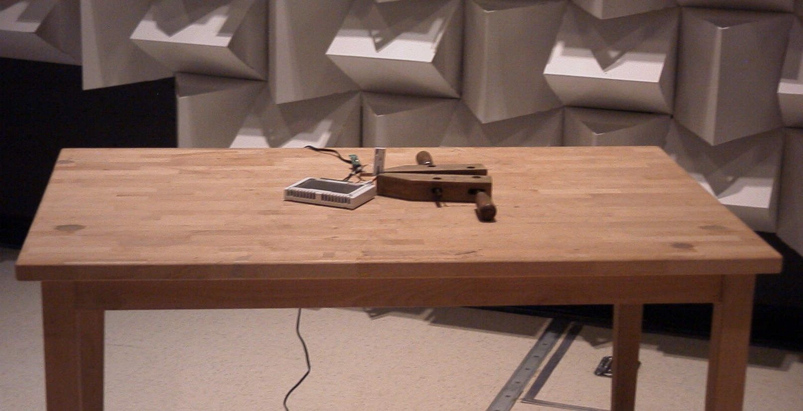
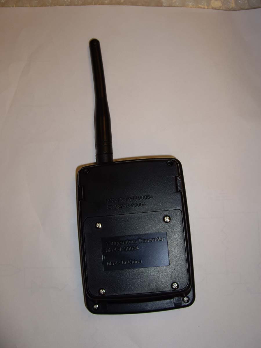
AED ELECTRONICS INC. FCC ID: RAN90164 EXTERNAL PHOTO
Internal Photos
AED ELECTRONICS INC. FCC ID: RAN90164 INTERNAL PHOTOS
Test Report
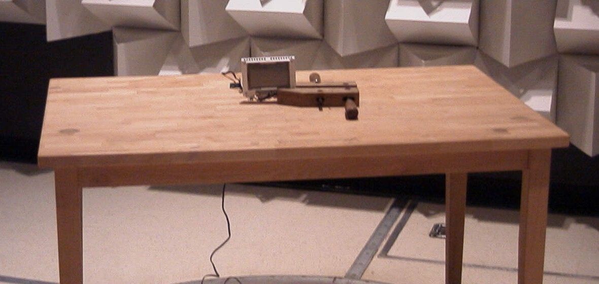
FCC PART 15.247 TEST REPORT APPLICANT AED ELECTRONICS INC. 5756 ROYALMOUNT AVENUE MONTREAL QUEBEC H4P 1K5 CANADA FCC ID RAN90164 PRODUCT DESCRIPTION Thermostat Transceiver DATE SAMPLE RECEIVED May 15, 2006 DATE TESTED June 6, 2006 TESTED BY Nam Nguyen APPROVED BY Mario de Aranzeta TIMCO REPORT NO. A\AED\1025AUTestReport TEST RESULTS PASS FAIL THE ATTACHED REPORT SHALL NOT BE REPRODUCED EXCEPT IN FULL WITHOUT THE WRITTEN APPROVAL OF TIMCO ENGINEERING, INC. 849 NW STATE ROAD 45 NEWBERRY, FL 32669 USA PH: 888.472.2424 OR 352.472.5500 FAX: 352.472.2030 EMAIL: [email protected] HTTP://WWW.TIMCOENGR.COM Certificate # 0955-01 Certificate # 0955-01 APPLICANT: AED ELECTRONICS INC. FCC ID: RAN90164 REPORT: V:\A\AED_\1025AUT6\1025AUT6TestReport.doc Page 2 of 15 TABLE OF CONTENTS STATEMENT OF COMPLIANCE.................................................................................. 3 GENERAL INFORMATION .......................................................................................... 4 EMC EQUIPMENT LIST ............................................................................................. 5 TEST PROCEDURE ................................................................................................... 6 POWER LINE CONDUCTED INTERFERENCE............................................................. 7 POWER OUTPUT ....................................................................................................... 9 NUMBER OF HOPPING CHANNELS ......................................................................... 10 DWELL TIME OF A HOPPING CHANNEL .................................................................. 11 CARRIER FREQUENCY SEPARATION ...................................................................... 12 20 dB BANDWIDTH ................................................................................................. 13 RADIATED SPURIOUS EMISSIONS INTO ADJACENT RESTRICTED BAND............... 14 FIELD STRENGTH OF SPURIOUS EMISSIONS......................................................... 15 Certificate # 0955-01 APPLICANT: AED ELECTRONICS INC. FCC ID: RAN90164 REPORT: V:\A\AED_\1025AUT6\1025AUT6TestReport.doc Page 3 of 15 STATEMENT OF COMPLIANCE This equipment has been tested in accordance with the standards identified in the referenced test report. To the best of my knowledge and belief, these tests were performed using the measurement procedures described in this report and demonstrate that the equipment complies with the appropriate standards. No modifications were made to the equipment during testing in order to demonstrate compliance with these standards. I attest that the necessary measurements were made by me or under my supervision, at: Timco Engineering, Inc. located at 849 N.W. State Road 45, Newberry, Florida 32669 USA. Authorized by: Mario de Aranzeta Function: Engineer Date: August 18, 2006 Tested by: Nam Nguyen Certificate # 0955-01 APPLICANT: AED ELECTRONICS INC. FCC ID: RAN90164 REPORT: V:\A\AED_\1025AUT6\1025AUT6TestReport.doc Page 4 of 15 GENERAL INFORMATION DUT Specification The test results relate only to the items tested. DUT Description FHSS Transceiver FCC ID RAN90164 Model Number See manufacturer list Serial Number N/A Operating Frequency 903 – 915 MHz No. of Channels 64 110–120Vac/50– 60Hz DC Power DUT Power Source Battery Operated Exclusively Prototype Pre-Production Test Item Production Fixed Mobile Type of Equipment Portable Antenna Wire monopole Antenna Connector None, permanently attached antenna Test Facility: The test sites used by Timco Engineering Inc. for radiated and conducted emissions are located at 849 NW State Road 45 Newberry, FL 32669 USA. Test Condition: The DUT was tested in the laboratory in an environment with normal temperature and humidity. The temperature was 26ºC with a relative humidity of 50%. Modification to the DUT: No modification was made to the DUT during testing. Test Exercise (e.g software description, test signal, etc.): The DUT was placed in continuous transmit mode of operation. Applicable Standards: TIA 603 FCC CFR 47 Part 15.247 Certificate # 0955-01 APPLICANT: AED ELECTRONICS INC. FCC ID: RAN90164 REPORT: V:\A\AED_\1025AUT6\1025AUT6TestReport.doc Page 5 of 15 EMC EQUIPMENT LIST Device Manufacturer Model Serial Number Cal/Char Date Due Date 3-Meter OATS TEI N/A N/A Listed 1/11/06 1/10/09 Antenna: Biconnical Eaton 94455-1 1057 CAL 12/12/05 12/12/07 Antenna: Biconnical Eaton 94455-1 1096 CAL 8/17/04 8/17/06 Antenna: Biconnical Electro- Metrics BIA-25 1171 CAL 4/29/05 4/29/07 Antenna: Double- Ridged Horn Electro- Metrics RGA-180 2319 CAL 12/29/04 12/29/06 LISN Electro- Metrics ANS-25/2 2604 CAL 8/27/04 8/27/06 LISN Electro- Metrics EM-7820 2682 CAL 4/28/05 4/28/07 Antenna: Log- Periodic Eaton 96005 1243 CAL 12/14/05 12/14/07 Certificate # 0955-01 APPLICANT: AED ELECTRONICS INC. FCC ID: RAN90164 REPORT: V:\A\AED_\1025AUT6\1025AUT6TestReport.doc Page 6 of 15 TEST PROCEDURE Power Line Conducted Interference: The procedure used was ANSI STANDARD C63.4- 2003 using a 50uH LISN. Both lines were observed with the UUT transmitting. The bandwidth of the spectrum analyzer was 10 kHz with an appropriate sweep speed. Bandwidth 20 dB: The measurements were made with the spectrum analyzer's resolution bandwidth (RBW) = 1 MHz and the video bandwidth (VBW) = 3 MHz and the span set as shown on plot. Power Output: The RF power output was measured at the antenna feed point using a peak power meter. Antenna Conducted Emissions: The RBW = 100 kHz, VBW = 300 kHz and the span set to 10.0 MHz and the spectrum was scanned from 30 MHz to the 10 th Harmonic of the fundamental. Above 1 GHz the resolution bandwidth was 1 MHz and the VBW = 3 MHz and the span to 50 MHz. Radiation Interference: The test procedure used was ANSI STANDARD C63.4-2003 using an Agilent spectrum receiver with pre-selector. The bandwidth (RBW) of the spectrum receiver was 100 kHz up to 1 GHz and 1 MHz above 1 GHz with an appropriate sweep speed. The VBW above 1 G…
Text truncated - open the document above for the full version.
Contact Information
Applicant
Howard Rosen(President)
Test Firm
Timco Engineering, Inc.Sid Sanders
Technical Specifications
| # | Rule Parts | Frequency Range | Power Output |
|---|---|---|---|
| 1 | 15C | 903.5 MHz - 914.9 MHz | 16.00 mW |
Other Applications from AED Electronics Inc.
RAN90064
Aug 30, 2006TRANSCEIVER
Equipment Class
DSS - Part 15 Spread Spectrum Transmitter
RAN217S31
Jul 22, 2003THERMOSTAT - TX
Equipment Class
DSC - Part 15 Security/Remote Control Transmitter