RAXAR4505NWDIGITAL TRANSMISSION SYSTEM
Arcadyan Technology Corporation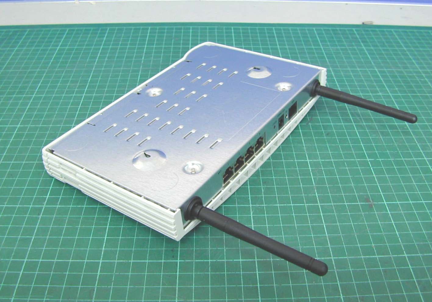
Click to zoom
Application Details
- Equipment Class
- DTS - Digital Transmission System
- Date of Grant
- Apr 10, 2006
- Application Purpose
- Original Equipment
- Date of Application
- Apr 10, 2006
- Equipment Note
- DIGITAL TRANSMISSION SYSTEM
- Frequency Range
- 2412.00000000 - 2462.00000000
- Country
- Taiwan
Documents & Files
Document Text
Text extracted from the exhibit documents filed with the FCC. Open a document above to read the original.
Users Manual
http://www.3com.com/ Part No. DUA100A-72AAA02 Published February 2006 OfficeConnect ® User Guide Model 3Com Corporation 350 Campus Drive, Marlborough, MA USA 01752-3064 Copyright © 2004, 2005, 2006, 3Com Corporation. All rights reserved. No part of this documentation may be reproduced in any form or by any means or used to make any derivative work (such as translation, transformation, or adaptation) without written permission from 3Com Corporation. 3Com Corporation reserves the right to revise this documentation and to make changes in content from time to time without obligation on the part of 3Com Corporation to provide notification of such revision or change. 3Com Corporation provides this documentation without warranty, term, or condition of any kind, either implied or expressed, including, but not limited to, the implied warranties, terms or conditions of merchantability, satisfactory quality, and fitness for a particular purpose. 3Com may make improvements or changes in the product(s) and/or the program(s) described in this documentation at any time. If there is any software on removable media described in this documentation, it is furnished under a license agreement included with the product as a separate document, in the hard copy documentation, or on the removable media in a directory file named LICENSE.TXT or !LICENSE.TXT. If you are unable to locate a copy, please contact 3Com and a copy will be provided to you. UNITED STATES GOVERNMENT LEGEND If you are a United States government agency, then this documentation and the software described herein are provided to you subject to the following: All technical data and computer software are commercial in nature and developed solely at private expense. Software is delivered as “Commercial Computer Software” as defined in DFARS 252.227-7014 (June 1995) or as a “commercial item” as defined in FAR 2.101(a) and as such is provided with only such rights as are provided in 3Com’s standard commercial license for the Software. Technical data is provided with limited rights only as provided in DFAR 252.227-7015 (Nov 1995) or FAR 52.227-14 (June 1987), whichever is applicable. You agree not to remove or deface any portion of any legend provided on any licensed program or documentation contained in, or delivered to you in conjunction with, this User Guide. Unless otherwise indicated, 3Com registered trademarks are registered in the United States and may or may not be registered in other countries. 3Com, and the 3Com logo are registered trademarks of 3Com Corporation. Intel and Pentium are registered trademarks of Intel Corporation. Microsoft, MS-DOS, Windows, and Windows NT are registered trademarks of Microsoft Corporation. Novell and NetWare are registered trademarks of Novell, Inc. UNIX is a registered trademark in the United States and other countries, licensed exclusively through X/Open Company, Ltd. Netscape Navigator is a registered trademark of Netscape Communications. JavaScript is a trademark of Sun Microsystems Wi-Fi and the Wi-Fi logo are registered trademarks of the WI-Fi Alliance. IEEE and 802 are trademarks of the Institute of Electrical and Electronics Engineers, Inc. All other company and product names may be trademarks of the respective companies with which they are associated. ENVIRONMENTAL STATEMENT It is the policy of 3Com Corporation to be environmentally-friendly in all operations. To uphold our policy, we are committed to: Establishing environmental performance standards that comply with national legislation and regulations. Conserving energy, materials and natural resources in all operations. Reducing the waste generated by all operations. Ensuring that all waste conforms to recognized environmental standards. Maximizing the recyclable and reusable content of all products. Ensuring that all products can be recycled, reused and disposed of safely. Ensuring that all products are labelled according to recognized environmental standards. Improving our environmental record on a continual basis. End of Life Statement 3Com processes allow for the recovery, reclamation and safe disposal of all end-of-life electronic components. Regulated Materials Statement 3Com products do not contain any hazardous or ozone-depleting material. Environmental Statement about the Documentation The documentation for this product is printed on paper that comes from sustainable, managed forests; it is fully biodegradable and recyclable, and is completely chlorine-free. The varnish is environmentally-friendly, and the inks are vegetable-based with a low heavy-metal content. CONTENTS ABOUT THIS GUIDE Naming Convention7 Conventions8 Feedback About This User Guide8 Related Documentation9 INTRODUCING THE ROUTER OfficeConnect ADSL Wireless 11g Firewall Router11 Router Advantages13 Package Contents13 Minimum System and Component Requirements14 Physical Features14 INSTALLING THE ROUTER Introduction17 Safety Information17 Positioning the Router17 Using the Rubber Feet18 Powering Up the Router18 Connecting the Router18 SETTING UP YOUR COMPUTERS Obtaining an IP Address Automatically23 Windows 200023 Windows XP25 Windows 98/ME25 Macintosh25 Disabling PPPoE and PPTP Client Software26 Disabling Web Proxy26 RUNNING THE SETUP WIZARD Accessing the Setup Wizard27 Setup Wizard - Change Password30 Setup Wizard - Time and Time Zone30 Setup Wizard - Connection Type31 Setup Wizard - LAN Settings36 Setup Wizard - Wireless Settings37 Setup Wizard - Configuration Summary38 CONFIGURING THE ROUTER Navigating Through the Router Configuration Pages39 Main Menu39 Welcome Screen39 Status39 LAN Settings40 LAN Settings40 DHCP Clients List41 Wireless Settings43 Configuration44 Encryption45 Connection Control50 Client List51 WDS Settings51 Advance52 Profile53 Internet Settings54 ATM PVC54 DNS65 Hostname & Clone MAC address66 Firewall67 SPI67 Special Applications71 Virtual Servers72 DMZ73 Schedule Rule74 PC Privileges75 URL Filter77 Server Control79 Quality of Service81 QoS Settings81 T…
Text truncated - open the document above for the full version.
Users Manual
Accessing the Setup Wizard35 1Enter your Internet IP address in the WAN IP field. 2Enter the subnet mask in the Subnet Mask field. 3Enter the default gateway IP address in the Default Gateway field. 4Enter the DNS address in the DNS field. 5Enter your VPI and VCI information in the VPI/VCI fields. 6Select the encapsulation type (LLC or VC MUX) in the Encapsulation drop-down menu. This information should be provided to you by your ISP. 7Check all of your settings, and then click Next. The LAN Settings screen will then be displayed (refer to Figure 24 ). Dynamic/Fixed IP in 1483 Bridge Mode (For Multiple PCs) For bridge mode to work, you need to assign an IP address to the Router. You can either configure the Router to obtain an IP address automatically from a DHCP server or assign a fixed or static IP address to it. Figure 23 Dynamic/Fixed IP for Bridge Mode Screen To obtain an IP address automatically from a DHCP server: Check the Get WAN IP By DCHP checkbox, and then click Next. The LAN Settings screen will then be displayed (refer to Figure 24 ). 36CHAPTER 4: RUNNING THE SETUP WIZARD To assign a fixed IP address: 1Enter your Internet IP address in the WAN IP field. 2Enter the subnet mask in the Subnet Mask field. 3Enter the default gateway IP address in the Default Gateway field. 4Enter the DNS address in the DNS field. 5Enter your VPI and VCI information in the VPI/VCI text boxes. 6Select the encapsulation type (LLC or VC MUX) in the Encapsulation drop-down menu. This information should be provided to you by your ISP. 7Check all of your settings, and then click Next. The LAN Settings screen will then be displayed (refer to Figure 24 ). Setup Wizard - LAN Settings The LAN Settings screen allows you to set the default IP address and DHCP client IP range for the Router. Figure 24 The LAN Settings Screen 1To change the Router’s default IP address, enter the new IP address in the IP Address field, and then enter the subnet mask in the Subnet Mask field. 2Select the On/Off button to turn on/turn off the DHCP function in the DHCP Server field. 3Enter the client IP address range in the IP Pool Start Address and IP Pool End Address fields. 4Click Next. The Wireless Settings screen will be displayed (refer to Figure 25 ). Accessing the Setup Wizard37 Setup Wizard - Wireless Settings The Wireless Settings screen allows you to set up the SSID and radio channel used for the wireless connection. Figure 25 Wireless Settings Screen 1Select the channel you want to use from the Channel drop-down menu. 2Specify the SSID to be used by your Wireless Network in the SSID field. If there are other wireless networks in your area, you should give your wireless network an unique name. 38CHAPTER 4: RUNNING THE SETUP WIZARD Setup Wizard - Configuration Summary When you have completed the Setup Wizard, a configuration summary will appear. Verify the configuration information of the Router and then click Apply to save your settings. 3Com recommends that you print out this page for your records. Figure 26 Configuration Summary Screen Your Router is now configured and ready for use. See Chapter 5 for a detailed description of the Router configuration. 5 CONFIGURING THE ROUTER Navigating Through the Router Configuration Pages This chapter describes all the screens available through the Router configuration pages, and is provided as a reference. To get to the configuration pages, enter the Router’s default IP in the location bar of your browser. The default IP is http://192.168.1.1. However, if you changed the Router LAN IP address during initial configuration, use the new IP address instead. Enter your password to login to the management interface. (The default password is admin). Main MenuThe main menu is located on the left side, as shown in Figure 27 . When you click on an item from the main menu, that page will appear in the main part of the screen. Welcome ScreenThe Welcome screen shows the current software information. Status Figure 27 Welcome Screen 40CHAPTER 5: CONFIGURING THE ROUTER LAN SettingsYour Router is equipped with a DHCP server that will automatically assign IP addresses to each computer on your network. The factory default settings for the DHCP server will work with most applications. If you need to make changes to the settings, you can do so. The LAN settings screen allows you to: ■Change the default IP address of the Router. The default IP is 192.168.1.1 ■Change the Subnet Mask. The default setting is 255.255.255.0 ■Enable/Disable the DHCP Server Function. The default is ON (Enabled). ■Specify the Starting and Ending IP Pool address. The default is Starting: 2 / Ending: 254. ■Specify the IP address Lease Time. The default is Half day. ■Specify a local Domain Name. The default is NONE. The Router will also provide a list of all client computers connected to the Router. LAN SettingsThe LAN Settings screen is used to specify the LAN IP address of your Router, and to configure the DHCP server. Figure 28 LAN Settings Screen 1Enter the Router’s IP Address and Subnet Mask in the appropriate fields. The default IP address is 192.168.1.1. 2If you want to use the Router as a DHCP Server, select On in the DHCP Server field. LAN Settings41 3Enter the IP address range in the IP Pool Start Address and IP Pool End Address fields. 4Specify the DHCP Lease time by selecting the required value from the Lease Time drop-down menu. The lease time is the length of time the DHCP server will reserve the IP address for each computer. 5Specify the Local Domain Name for your network (this step is optional). 6Enter the IP address of the NBX Call Processor in the 3Com NBX Call Processor field (this step is optional). 7Check all of your settings, and then click Apply. DHCP Clients ListThe DHCP Clients List provides details on the devices that have received IP addresses from the Router. The list is only created when the Router is set up as a DHCP server. The maximum number of 253 clients can be connected to the Router. Figure 29…
Text truncated - open the document above for the full version.
Users Manual
Firewall71 Special ApplicationsSpecial Applications let you choose specific ports to be open for specific applications to work properly with the Network Address Translation (NAT) feature of the Router. Figure 56 Special Applications Screen A list of popular applications has been included to choose from. Select your application from the Popular Applications drop-down menu. Then select the row that you want to copy the settings to from the Copy To drop-down menu, and click Copy To. The settings will be transferred to the row that you specified. Click Apply to save the setting for that application. If your application is not listed, you will need to check with the application vendor to determine which ports need to be configured. You can manually enter the port information into the Router. To manually enter the port information: 1Specify the trigger port (the one used by the application when it is initialized) in the Trigger Port column, and specify whether the trigger is TCP or UDP. 2Specify the Public Ports used by the application, that will need to be opened up in the firewall for the application to work properly. Also specify whether these ports are TCP or UDP. 3Check the Enabled checkbox, then click Apply. 72CHAPTER 5: CONFIGURING THE ROUTER Virtual ServersThe Virtual servers feature allows you to route external (Internet) calls for services such as a web server (port 80), FTP server (Port 21), or other applications through your Router to your internal network. Since your internal computers are protected by a firewall, machines from the Internet cannot get to them because they cannot be 'seen'. If you need to configure the Virtual Server function for a specific application, you will need to contact the application vendor to find out which port settings you need. The maximum number of virtual servers that can be configured is 20. Figure 57 Virtual Servers Screen A list of popular servers has been included to choose from. Select the server from the Popular servers drop-down menu. Then click Add, your selection will be added to the table. If the server that you want to use is not listed in the drop-down menu, you can manually add the virtual server to the table. To manually configure your virtual servers: 1Enter the IP address, and the description in the spaces provided for the internal machine. 2Select the protocol type (TCP, UDP, or both TCP and UDP) from the drop-down menu. 3Specify the public port that will be seen by clients on the Internet, and the LAN port which the traffic will be routed to. Firewall73 4You can enable or disable each Virtual Server entry by checking or unchecking the appropriate Enabled checkbox. 5Click Apply to save the changes for each Virtual Server entry. DMZIf you have a client PC that cannot run an Internet application properly from behind the firewall, you can open the client up to unrestricted two-way Internet access. This may be necessary if the NAT feature is causing problems with an application such as a game or video conferencing application. Figure 58 DMZ Screen Use this feature on a temporary basis. The computer in the DMZ is not protected from hacker attacks. To put a computer in the DMZ: 1Check the Enable 1-to-1 NAT checkbox. 2Enter the last digits of the LAN IP address in the Client PC IP Address field. Enter the IP address (if known) that will be accessing the DMZ PC into the Public IP Address field, so that only the computer on the Internet at this address can access the DMZ PC without firewall protection. If the IP address is not known, or if more than one PC on the Internet will need to access the DMZ PC, then set the Public IP Address to 0.0.0.0. 3Click Apply. 74CHAPTER 5: CONFIGURING THE ROUTER Schedule RuleThe Router can be configured to restrict access to the Internet, email or other network services at specific days and times. Define the time in this page, and define the rules in the PC Privileges page (see page 75 ). Figure 59 Schedule Rule Screen 1Click Add Rule to add a schedule rule (a screen similar to Figure 60 will appear). Figure 60 Add Schedule Rule Screen 2Enter a name and comment for the schedule rule in the Name and Comment fields. 3Specify the schedule rules for the required days and times - note that all times should be in 24 hour format. 4Click Apply. Firewall75 PC PrivilegesThe Router can be configured to restrict access to the Internet, email or other network services at specific days and times. Restriction can be set for a single computer, a range of computers, or multiple computers. You can define the traffic type permitted or not-permitted to the Internet. Figure 61 PC Privileges Screen To edit or delete specific existing filtering rules, click on Edit or Delete for the appropriate filtering rule. To configure a new filtering rule: 1Check the Enable Filtering Function checkbox. 2Click Add PC (a screen similar to Figure 62 will appear). Figure 62 PC Privileges Add PC Screen 76CHAPTER 5: CONFIGURING THE ROUTER 3Enter a description in the Client PC Description field, and the IP address or IP address range into the Client PC IP Address fields. 4To bypass the URL Filter and Content Filter, check the corresponding Bypass checkbox. 5Select the services to be blocked. A list of popular services is given on this screen, to block a particular service, check the appropriate Blocking checkbox. If the service to be restricted is not listed here, you can enter a custom range of ports at the bottom of the page, under User Defined Blocked Ports. 6If you want the restriction to apply only at certain times, select the schedule rule to apply from the Schedule Rule drop-down menu. Note that schedule rules are defined on the Schedule Rules screen (see page 74 ). 7Click Apply to add the settings. Firewall77 URL FilterTo configure the URL filter feature, use the table on the URL Filter screen to specify the Web sites (www.somesite.com) and/or keywords you want to filter on your network. For example, entering a keyword of xxx would block acce…
Text truncated - open the document above for the full version.
Users Manual
Advanced89 Before you set up DDNS, you must obtain an account, password or key and static domain name from your DDNS provider. DDNS is disabled by default. Figure 74 Dynamic Domain Server (DDNS) Screen 1Check Enable DDNS. 2Select the provider, and then enter the necessary information provided by your DDNS provider. 3Click Apply. 90CHAPTER 5: CONFIGURING THE ROUTER SNMPSNMP (Simple Network Management Protocol) allows remote management of your router by a PC that has an SNMP management agent installed. Figure 75 SNMP Screen To Configure SNMP Community: 1In the Community column, enter the name of the SNMP communication channel. Your SNMP management agent needs to be configured with this name so that it can communicate with your router. 2In the Access column, select Read to allow the management agent to collect data (for example, bandwidth usage) from your router. Select Write to allow the management agent to change the configuration of your router. 3Check the appropriate Valid checkbox to enable the communication channel. Advanced91 You can configure your router to send status messages to the SNMP management agent if a problem occurs on the network. To configure SNMP traps: 1In the IP Address field, enter the IP address of the PC to which you want your router to send status messages. 2In the Community field, enter the name of the SNMP communication channel to which you want your router to send status messages. 3Set the Version field to match the version of trap messaging that your SNMP management agent supports. The router supports V1 and V2c trap messaging. SyslogUsing third party syslog software, this Syslog Server tool will automatically download the Router log to the specified server IP address. Figure 76 Syslog Server Screen 1Check the Enable Syslog Server checkbox. 2Enter the Server LAN IP Address in the space provided. 3Click Apply. 92CHAPTER 5: CONFIGURING THE ROUTER Proxy ARPProxy ARP is the technique in which one host, usually a router, answers ARP requests intended for another machine. By "faking" its identity, the router accepts responsibility for routing packets to the "real" or intended destination. This hightens the security for your network. Figure 77 Proxy ARP Screen Enter the corresponding IP address in the IP Address From and IP Address To fields. System Tools93 System ToolsThese pages allows you to manage different parameters of the Router and perform certain administrative functions. Restart RouterSometimes it may be necessary to restart (or reboot) the Router. Restarting the Router from this screen will not delete any of your configuration settings. Click the Restart the Router button to restart the Router. Figure 78 Restart Router Screen ConfigurationUse this configuration screen to backup, restore or reset the configuration details of the Router. Figure 79 Configuration Screen 94CHAPTER 5: CONFIGURING THE ROUTER ■Backup Configuration — You can save your current configuration by clicking the Backup button. Saving your configuration will allow you to restore it later if your settings are lost or changed. It is recommended that you backup your current configuration before performing a firmware update. ■Restore Configuration Data — The Restore Settings option will allow you to restore a previously saved configuration. Please select the configuration file using the Browse button and click Restore. ■Reset to Factory Default — Using this option will reset all of the settings in the Router to the factory default settings. It is recommended that you backup your settings before you restore all of the defaults. To restore the factory default settings, click Reset. UpgradeFrom time to time 3Com may release new versions of the Router’s firmware. Firmware updates contain improvements and fixes to problems that may have existed. Figure 80 Upgrade Screen Please download the firmware file to your PC first, and then click Browse and select the firmware file. Click Upgrade to upload the firmware to the Router. System Tools95 Time ZoneYou can set the time settings for the Router in this page. Figure 81 Time Zone Screen The Router keeps time by connecting to a Network Time Protocol (NTP) server. This allows the Router to synchronize the system clock to the Internet. The synchronized clock in the Router is used to record the security log and control client filtering. Select the time zone that you reside in. If you reside in an area that observes Daylight Saving, then check the checkbox for Enable Daylight Saving. The system clock may not update immediately. Allow at least 15 minutes for the router to contact the time servers on the Internet and get a response. You cannot set the clock yourself. You can specify which NTP servers the Router will use to update the system clock, although doing this should only be necessary if you are experiencing difficulty. 96CHAPTER 5: CONFIGURING THE ROUTER PingThe ping tool is used to test if the network is working properly. Figure 82 Ping Screen 1Enter the IP address or domain name in the IP Address or Domain Name field, and click Ping. 2Select from the Number of times to Ping drop-down menu. 3The Router keeps a log of the ping test, click Clear Log to delete the records. System Tools97 TracerouteTraceroute is the program that shows you the route over the network between two systems, listing all the intermediate routers a connection must pass through to get to its destination. It can help you determine why your connections to a given server might be poor, and can often help you figure out where exactly the problem is. It also shows you how systems are connected to each other, letting you see how your ISP connects to the Internet as well as how the target system is connected. Figure 83 Traceroute Screen 1Enter the IP address or domain name in the IP Address or Domain Name field, and click Tr a c e r o u t e. 2The Router keeps a log of the trace route test, click Clear Log to delete the records. 98CHAPTER 5: CONFIGURING THE ROUTER DNS LookupDNS Lookup is t…
Text truncated - open the document above for the full version.
Cover Letter(s)
Company Arcadyan Technology Corporation Address 4F, No. 9, Park Avenue II, Science-based Industrial Park, Hsinchu 300, Taiwan Country Taiwan Telephone number 886-3-5787000 Fax number 886-3-5637325 Internet [email protected] Federal Communications Commission Authorization and Evaluation Division Confidentiality Request RE: FCC ID: RAXAR4505NW Pursuant to Sections 0.457 and 0.459 of the Commission’s Rules, the Applicant hereby requests confidential treatment of information accompanying this Application as outlined below: Schematics.pdf Block Diagram.pdf Technical Descriptions.pdf The above materials contain trade secrets and proprietary information not customarily release to the public. The public disclosure of these matters might be harmful to the Applicant and Provide unjustified benefits to its competitors. The Applicant understands that pursuant to Rule 0.457, disclosure of this Application and all accompanying documentation will not be made before the data of the Grant for this application. Sincerely, Simon Liu Manager Arcadyan Technology Corporation
External Photos
Photo 1: External photo of EUT WL-552 Photo 2: External photo of EUT WL-552
ID Label/Location Info
FCC ID Label Location
Internal Photos
Photo 1: Internal photo of EUT WL-552 Photo 2: Internal photo of EUT WL-552 Photo 3: Internal photo of EUT WL-552 Photo 4: Internal photo of EUT WL-552
RF Exposure Info
FCC ID. : RAXAR4505NW Report No.: EME-060250 Page 1 of 5 Maximum Permissible Exposure (MPE) Evaluation Report Report No. : EME-060250 Model No. : WL-552 Issued Date : Apr. 7, 2006 Applicant : Arcadyan Technology Corporation 4F, No. 9, Park Avenue II, Science-based Industrial Park, Hsinchu 300, Taiwan Test By : Intertek Testing Services Taiwan Ltd. No. 11, Lane 275, Ko-Nan 1 Street, Chia-Tung Li, Shiang-Shan District, Hsinchu City, Taiwan This test report consists of 5 pages in total. It may be duplicated completely for legal use with the allowance of the applicant. It shall not be reproduced except in full, without the written approval of Intertek Laboratory. The test result(s) in this report only applies to the tested sample(s). Jerry Liu Project Engineer Reviewed By Kevin Chen FCC ID. : RAXAR4505NW Report No.: EME-060250 Page 2 of 5 Table of Contents Summary of Tests ............................................................................................................. 3 1. Introduction .................................................................................................................. 4 2. RF Exposure Limit ....................................................................................................... 4 3. RF Exposure calculations ............................................................................................. 5 4. Test results .................................................................................................................... 5 FCC ID. : RAXAR4505NW Report No.: EME-060250 Page 3 of 5 Summary of Tests MPE Evaluation meet FCC OET No. 65: 1997/ IEEE C95.1-1999 OfficeConnect ADSL Wireless 54Mbps 11g Firewall Router-Model: WL-552 FCC ID: RAXAR4505NW Test Reference Results MPE Evaluation FCC Guidelines for Human Exposure IEEE C95.1 Complies FCC ID. : RAXAR4505NW Report No.: EME-060250 Page 4 of 5 1. Introduction The EUT operates in the 2.4GHz ISM band. Due to the EUT (include antenna) at its normal operation distance is at least 20 cm from the human body, the EUT was defined as a Mobile Device. The reason to do the MPE Evaluation is to avoid the RF hazard to human body. The maximum output power and gain of the antenna were used to calculate the limited Power density (S) at 20cm distance away from the product. The limit for Maximum Permissible Exposure (MPE) specified in FCC 1.1310 is followed. 2. RF Exposure Limit According to FCC 1.1310: The criteria listed in the following table shall be used to evaluate the environmental impact of human exposure to radio-frequency (RF) radiation as specified in 1.1307(b). Limits for Maximum Permissible Exposure (MPE) Frequency Range (MHz) Electric Field Strength (V/m) Magnetic Field Strength (A/m) Power Density (mW/cm 2 ) Average Time (minutes) (A) Limits for Occupational / Control Exposures 30-300 61.4 0.163 1.0 6 300-1500 - - F/300 6 1500-100,000 - - 5 6 (B) Limits for General Population / Uncontrolled Exposure 30-300 27.5 0.073 0.2 30 300-1500 - - F/1500 30 1500-100,000 - - 1.0 30 F= Frequency in MHz FCC ID. : RAXAR4505NW Report No.: EME-060250 Page 5 of 5 3. RF Exposure calculations From §FCC 1.1310 table 1, the maximum permissible RF exposure for an uncontrolled environment is 1mW/(cm 2 ) Power density (S) is calculated by the following formula: S = (P * G)/4πR 2 where, S = Power density (mW/cm 2 ) P = Output power to antenna (mW) R = Distance between radiating structure and observation point (cm) G = Gain of antenna in numeric π = 3.1416 Example: Assume a mobile device operates at 2412MHz and its maximum output power is 50mW, and the maximum gain of antenna is 1 (numeric) /0dBi. then the power density (S) = (50 * 1)/4*π*20 2 = 0.00995 (mW/cm 2 ) 4. Test results Test Mode: 802.11b (DSSS Modulation) operating mode Channel Channel Frequency (MHz) Maximum antenna gain (numeric) Output power to antenna (mW) Power density (mW/cm 2 ) Limit of power density (mW/cm 2 ) 1 2412 1.58 138.68 0.044 1.0 6 2437 1.58 137.40 0.043 1.0 11 2462 1.58 141.91 0.045 1.0 Test Mode: 802.11g (OFDM Modulation) operating mode Channel Channel Frequency (MHz) Maximum antenna gain (numeric) Output power to antenna (mW) Power density (mW/cm 2 ) Limit of power density (mW/cm 2 ) 1 2412 1.58 345.94 0.109 1.0 6 2437 1.58 348.34 0.110 1.0 11 2462 1.58 344.35 0.109 1.0 The Notice in Installation Manual has been stated as below: While installing and operating this transmitter, the radio frequency exposure limit of 1mW/(cm*cm) may be exceeded at distances close to the transmitter. therefore, the user must maintain a minimum distance of 20 cm from the device at all time.
Test Report
FCC ID. : RAXAR4505NW Report No.: EME-060250 Page 1 of 46 EMC TE…
Text truncated - open the document above for the full version.
Contact Information
Applicant
Simon Liu(Manager)
Test Firm
Intertek Testing Services Taiwan Ltd.Alpha Liu
Technical Specifications
| # | Rule Parts | Frequency Range | Power Output |
|---|---|---|---|
| 1 | 15C | 2.41 GHz - 2.46 GHz | 348.30 mW |
Other Applications from Arcadyan Technology Corporation
RAXWE6204430
Jan 27, 2024Wi-Fi Extender
Equipment Class
DTS - Digital Transmission System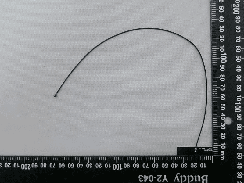
RAXAIOS7
Nov 08, 2023HEOS 7.0 Platform Module
Equipment Class
NII - Unlicensed National Information Infrastructure TX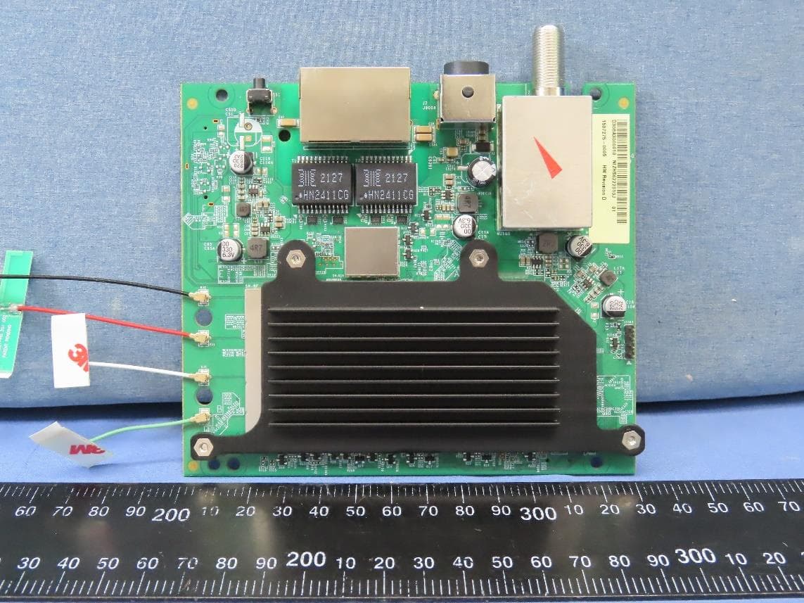
RAXWR3210
Jul 13, 2023Standalone Router
Equipment Class
DTS - Digital Transmission System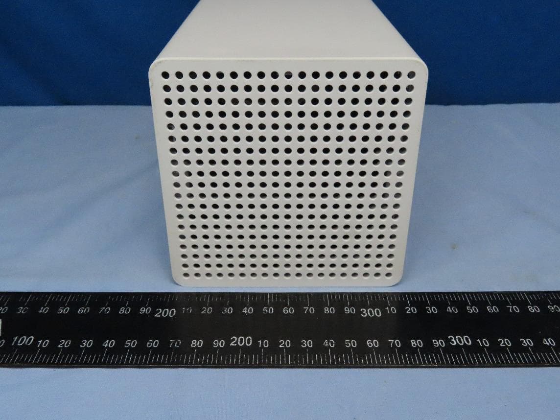
RAXWE7224443
Jan 11, 2023Verizon Wi-Fi Extender
Equipment Class
6PP - 15E 6 GHz Subordinate Indoor Device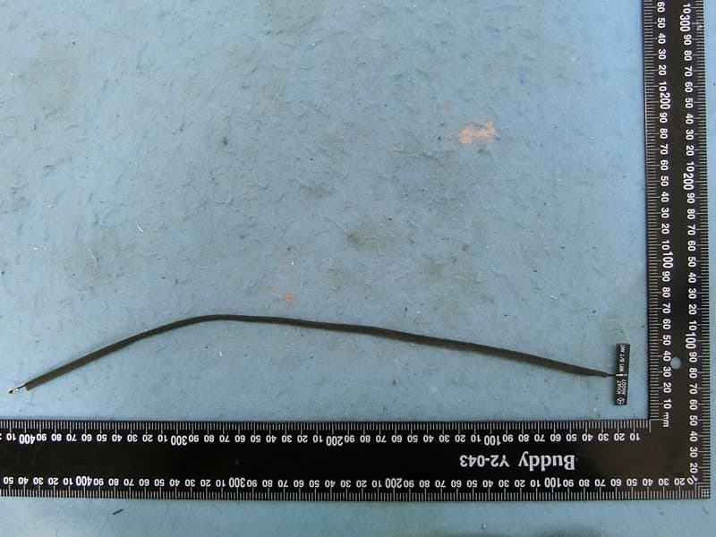
RAXAIOS65V
Nov 06, 2022HEOS 6.5 Platform Module
Equipment Class
DSS - Part 15 Spread Spectrum Transmitter