RAXWA8001BAC4x4 Video bridge
Arcadyan Technology Corporation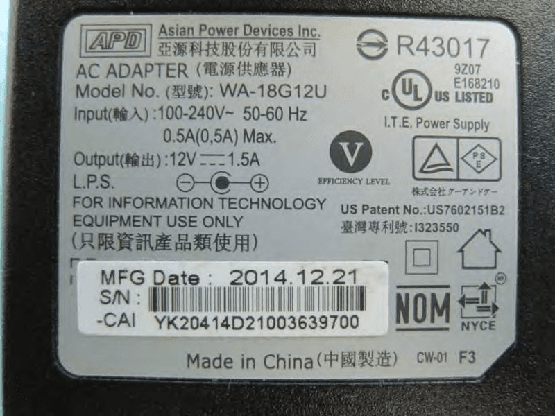
Click to zoom
Application Details
- Equipment Class
- DTS - Digital Transmission System
- Date of Grant
- Mar 30, 2015
- Application Purpose
- Original Equipment
- Date of Application
- Mar 29, 2015
- Equipment Note
- 4x4 Video bridge
- Frequency Range
- 5745.00000000 - 5825.00000000
- Country
- Taiwan
Documents & Files
Document Text
Text extracted from the exhibit documents filed with the FCC. Open a document above to read the original.
Users Manual
GXT542U Gigabit Wi-Fi Extender QUICK INSTALL GUIDE This guide will facilitate installation of the GXT 5G model number GXT542U Gigabit Wi-Fi Extender which may be configured as a: • Multicast (IPTV) Video Bridge Access Point (AP) (Section 1) • Multicast (IPTV) Video Bridge Client (Section 2) • Gigabit Wi-Fi AP (Section 3) • Gigabit Wi-Fi Clie nt (Section 4) Pr ior t o starting, ensure you h ave one each: • GXT542U unit • CAT5 Ethernet cable • Power adapter • Quic k Installation Guide 2 MULTICAST (IPTV) VIDEO BRIDGE INSTALLATION Section 1 Multicast (IPTV) Video Bridge AP Installation The initial GXT542U must be installed as an AP Step 1 – Unit Mode Configuration A. On the back of the device, set the unit mode switch to AP (left posit ion) as ill ustrated bel ow. Step 2 – Power and LEDs A. Plug in the 12V A/C adapter and co nnect it to the GXT542U AP. Verify the AP / STA LED is BLUE indicating AP mode. Changing the mode from AP (Blue) to Client or Stat ion (STA) (Green) requires a power cycle. Step 3 – Placement and network connec tions A. Place the GXT542U AP near the ONT/Residential Gateway 3 B. Insert one end of an Ethernet cable into the Video LAN port of the ONT/ RG with the other to th e GXT542U’s RJ-4 5 port. Section 2 DO NOT connect both Ethernet ports on the AP to the same subnetwork ports on the ONT/Gateway as this will create a loop and disrupt traffic. Multicast (IPTV) Video Bridge Client Installation After installing a GXT542U AP per Section 1, Clients can be added using the steps b elow: Step 1 – Unit Mode Configuration A. Set the unit mode switch at the back of the unit to STA (Right posit ion) as ill ustrated b elow. Step 2 - Power and LEDs A. Plug in the 12V A/C adapter and co nnect it to the G XT542U STA unit. Verify the AP / STA LED is GREEN indicating Client (STA) mode. Home Gateway or Cable/DSL Modem 4 Step 3 – Placement and network connec tions A. Place the GXT542U Client near the Multicast Video Set-Top Box (STB). B. Insert the Ethernet cable into the STB and the other end into one of the Ethernet ports of the GXT542U. Step 4 – Pair the Client with theAP A. Press the WPS button on the back of the GXT542U AP. The WPS LED on the top front will flash for up to 2 minutes, indicating it i s ready for association with Client s. B. Within 2 minutes, press the WPS button on the GXT542U Client. The WPS LED will continue flashing until associate d with the AP and stop at which t ime the WLAN LED will il luminate. WPS Button WPS LED 5 Client AP The WLAN LED color indicates the receiver signal str ength (RSSI) Green = Good, Blue = Fair, Red = Poor Step 5 – Install the DVR a nd STBs Congratulations. You have completed installation of a Gigabit Wi-Fi Multicast IPTV link. Turn on any TV c hannel for visual verification of the wireless connection q uality. Additional GXT542U c lients can b e paired to the AP following the guideline in Section 2. Step 6 – Verify the wireless performance Access the Web User Interface to verify the wireless capacity for watching and recording video. A. Set a ll TV(s) to the highest resolution HD channels B. Begin recording HD channels on the DVR (if installed) C. Ensure the laptop Ethernet port is configured to a fixed IP address of 10.0.0.50 6 D. Connect the PC to the AP via Ethernet, open a browser and enter the AP’s defa ult I P address http://10.0.0.2 to access the GXT542U. E. Login using user name: admin password: last 4 di gits of the MAC address (printed o n the bottom of the device) F. Click on the System Information on the left G. Ensure the Free Air Time i s GREEN H. Select Video Stat ion List I. Verify all the RSSI levels are GREEN or BLUE GIGABIT Wi-Fi INTERNET ACTIVATION AND AP AND CLIENT INSTALLATION Section 3 Activating the Gigabit Data Wi-Fi Network By default, the GXT542U Internet Network and associated SSID are not pre-configured. Steps 1 and 2 – Refer to Section 1 , Steps 1 and 2 instr uctions on page 2 Multicast (IPTV) Video Bridge AP Installation. When Mult icast Video (IPTV) and Internet Data originate on the SAME ONT/ RG port, connect the sing le Ethernet port to the GXT542U. Home Gateway or Cable/DSL Modem 7 If Mult icast Video (IPTV) and Internet Data originate o n SEPARATE ONT / RG ports, refer to the instr uctions on the att ached addendum Segregating Video & Inte rnet Ports. The 2 GE GXT542U ports are factory bridged and need to be reconfigured to segregate the se traffic types an d eliminate th e potential for IP relat ed issues. Step 3 – Activate the Internet Wi-Fi Network To login to the web Interface to create the Data Wi-Fi network: A. Follow Section 2, Step 6 C – E directions to access the AP web interface B. Click on the Data Wir eless Setup menu item on the left C. Check the box and click Apply t o enable the Data network D. Confirm the screen displays the Data wireless network Congratulations! You have activated and installed the Gigabit Wi-Fi Internet network. Connect any 5 GHz 11ac or 11n device to the Internet SSID using the passphrase below to a ccess the internet. e default passphrase for connecting to the Data Wi-Fi Network is the last 8 digits of the AP’s MAC address printed on the bottom. 8 SECTION 4 INSTALLING a Gigabit Wi-Fi Client The GXT542U configured as a Client offers an ultra-high performance Gigabit Wi-Fi connection to Gaming Consoles, SmartTVs and streaming devices such as FireTV, Roku and Apple TV. Steps 1 – 2 A. Follow the instructions outl ined in Section 2, Steps 1 – 2 substituting the Smart TV, Gaming Console or streaming device for the STB Step 3 – Pairing t he Client with theAP A. Follow the instructions below for pairing the Client to the Data Wir eless Network By default, the WPS function is associa ted with the Video Network. T o change the WPS capability to the Data Wireless Network, login to the WEB User Interface to set up the Data Wi-Fi network as the default WPS SSID. A. Follow Steps 1 -3 in Section 3 B. Click on the Data Wireless Setup menu item on the left C. Check the WPS Default o…
Text truncated - open the document above for the full version.
Cover Letter(s)
Arcadyan Technology Corporation No.8, Sec.2, Guangfu Rd., Hsinchu, 30071 Taiwan Tel: +886-3-5727000 / Fax: +886-3-5727063 Confidential Letter Date: 2015/3/17 Federal Communications Commission Authorization and Evaluation Division FCC ID:RAXWA8001BAC Confidentiality Request Pursuant to Sections 0.457 and 0.459 of the Commission’s Rules, the Applicant Hereby requests confidential treatment of information accomparting this Application As outlined below: ● Block Diagram ● Schematic Diagram ● Operational Description The above materials contain trade secrets and proprietary information not customarily released to the public. The public disclosure of these matters might be harmful to the Applicant and provide unjustified benefits to its competitors. The Applicant understands that pursuant to Rule 0.457, disclosure of this Application and all accompanying documentation will not be made before the date of the Grant for this application Sincerely, Applicant’s company name : Arcadyan Technology Corporation Applicant’s company address : No.8, Sec.2, Guangfu Rd., Hsinchu, 30071 Taiwan Signature : Name and Job Title : Simon Liu / Manager E-Mail : [email protected] Tel. : +886-3-5727000 # 14250
Cover Letter(s)
Arcadyan Technology Corporation No.8, Sec.2, Guangfu Rd., Hsinchu, 30071 Taiwan Tel: +886-3-5727000 / Fax: +886-3-5727063 DoC Attestation Letter Date: 2015/3/17 We Arcadyan Technology Corporation, as the grantee of this project (FCC ID: RAXWA8001BAC / Brand Name: Airsonics / Model No.: GXT542U), would like to declare that the composite portion categorized as computer peripheral has been authorized under the Declaration of Conformity procedures (Sporton report No.: FD511636, FCC designation number : TW1024). The final product shall consequently comply with the FCC rule applied for DoC Procedure. Regards, FCC Grantee contact person information. A pplicant’s company name : Arcadyan Technology Corporation Applicant’s company address : No.8, Sec.2, Guangfu Rd., Hsinchu, 30071 Taiwan Signature : Name and Job Title : Simon Liu / Manager E-Mail : [email protected] Tel. : +886-3-5727000 # 14250
Cover Letter(s)
Arcadyan Technology Corporation No.8, Sec.2, Guangfu Rd., Hsinchu, 30071 Taiwan Tel: +886-3-5727000 / Fax: +886-3-5727063 Power of Attorney Date: 2015/3/17 Dear Sir, I hereby have entrusted the following person to be a proxy regarding application for Type Certification. Sporton International Inc. Address : No.8, Lane 724, Bo-ai St., Jhubei City, HsinChu County 302, Taiwan, R.O.C. Name : Leo Huang Job Title : Manager e-mail : [email protected] I am therefore responsible for the contents of the application. Brand name and model type of the specified radio equipment: Airsonics / GXT542U FCC ID: RAXWA8001BAC Product name: 4x4 Video bridge FCC Grantee contact person information. A pplicant’s company name : Arcadyan Technology Corporation Applicant’s company address : No.8, Sec.2, Guangfu Rd., Hsinchu, 30071 Taiwan Signature : Name and Job Title : Simon Liu / Manager E-Mail : [email protected] Tel. : +886-3-5727000 # 14250
External Photos
Report No.:511636 SPORTON International Inc. PAGE NUMBER : A1 OF A5 TEL : 886-3-327-3456 FAX : 886-3-327-0973 APPENDIX A. Photographs of EUT Report No.:511636 SPORTON International Inc. PAGE NUMBER : A2 OF A5 TEL : 886-3-327-3456 FAX : 886-3-327-0973 Report No.:511636 SPORTON International Inc. PAGE NUMBER : A3 OF A5 TEL : 886-3-327-3456 FAX : 886-3-327-0973 Report No.:511636 SPORTON International Inc. PAGE NUMBER : A4 OF A5 TEL : 886-3-327-3456 FAX : 886-3-327-0973 Adapter Model No.: WA-18G12U Report No.:511636 SPORTON International Inc. PAGE NUMBER : A5 OF A5 TEL : 886-3-327-3456 FAX : 886-3-327-0973
ID Label/Location Info
Label: Size: 59.6 x 41.6 mm Label Here
Internal Photos
Report No.:511636 SPORTON International Inc. PAGE NUMBER : A1 OF A14 TEL : 886-3-327-3456 FAX : 886-3-327-0973 APPENDIX A. Photographs of EUT Report No.:511636 SPORTON International Inc. PAGE NUMBER : A2 OF A14 TEL : 886-3-327-3456 FAX : 886-3-327-0973 Report No.:511636 SPORTON International Inc. PAGE NUMBER : A3 OF A14 TEL : 886-3-327-3456 FAX : 886-3-327-0973 Report No.:511636 SPORTON International Inc. PAGE NUMBER : A4 OF A14 TEL : 886-3-327-3456 FAX : 886-3-327-0973 Report No.:511636 SPORTON International Inc. PAGE NUMBER : A5 OF A14 TEL : 886-3-327-3456 FAX : 886-3-327-0973 Report No.:511636 SPORTON International Inc. PAGE NUMBER : A6 OF A14 TEL : 886-3-327-3456 FAX : 886-3-327-0973 Report No.:511636 SPORTON International Inc. PAGE NUMBER : A7 OF A14 TEL : 886-3-327-3456 FAX : 886-3-327-0973 Report No.:511636 SPORTON International Inc. PAGE NUMBER : A8 OF A14 TEL : 886-3-327-3456 FAX : 886-3-327-0973 Report No.:511636 SPORTON International Inc. PAGE NUMBER : A9 OF A14 TEL : 886-3-327-3456 FAX : 886-3-327-0973 Report No.:511636 SPORTON International Inc. PAGE NUMBER : A10 OF A14 TEL : 886-3-327-3456 FAX : 886-3-327-0973 Report No.:511636 SPORTON International Inc. PAGE NUMBER : A11 OF A14 TEL : 886-3-327-3456 FAX : 886-3-327-0973 Report No.:511636 SPORTON International Inc. PAGE NUMBER : A12 OF A14 TEL : 886-3-327-3456 FAX : 886-3-327-0973 Report No.:511636 SPORTON International Inc. PAGE NUMBER : A13 OF A14 TEL : 886-3-327-3456 FAX : 886-3-327-0973 Report No.:511636 SPORTON International Inc. PAGE NUMBER : A14 OF A14 TEL : 886-3-327-3456 FAX : 886-3-327-0973
RF Exposure Info
Report No.: FR511636 FCC ID: RAXWA8001BAC Page No. : C1 of C3 Appendix C. Maximum Permissible Exposure Report No.: FR511636 FCC ID: RAXWA8001BAC Page No. : C2 of C3 1. Maximum Permissible Exposure 1.1. Applicable Standard Systems operating under the provisions of this section shall be operated in a manner that ensures that the public is not exposed to radio frequency energy levels in excess limit for maximum permissible exposure. In accordance with 47 CFR FCC Part 2 Subpart J, section 2.1091 this device has been defined as a mobile device whereby a distance of 0.2 m normally can be maintained between the user and the device. (A) Limits for Occupational / Controlled Exposure Frequency Range (MHz) Electric Field Strength (E) (V/m) Magnetic Field Strength (H) (A/m) Power Density (S) (mW/ cm²) Averaging Time |E|²,|H|² or S (minutes) 0.3-3.0 614 1.63 (100)* 6 3.0-30 1842 / f 4.89 / f (900 / f)* 6 30-300 61.4 0.163 1.0 6 300-1500 F/300 6 1500-100,000 5 6 (B) Limits for General Population / Uncontrolled Exposure Frequency Range (MHz) Electric Field Strength (E) (V/m) Magnetic Field Strength (H) (A/m) Power Density (S) (mW/ cm²) Averaging Time |E|²,|H|² or S (minutes) 0.3-1.34 614 1.63 (100)* 30 1.34-30 824/f 2.19/f (180/f)* 30 30-300 27.5 0.073 0.2 30 300-1500 F/1500 30 1500-100,000 1.0 30 Note: f = frequency in MHz ; *Plane-wave equivalent power density 1.2. MPE Calculation Method E (V/m) = d GP30 Power Density: Pd (W/m²) = 377 2 E E = Electric field (V/m) P = Average RF output power (W) G = EUT Antenna numeric gain (numeric) d = Separation distance between radiator and human body (m) The formula can be changed to Pd = 2 377 30 d GP From the EUT RF output power, the minimum mobile separation distance, d=0.2m, as well as the gain of the used antenna, the RF power density can be obtained. Report No.: FR511636 FCC ID: RAXWA8001BAC Page No. : C3 of C3 1.3. Calculated Result and Limit Exposure Environment: General Population / Uncontrolled Exposure For 5GHz Band (NII): Antenna Type : PIFA Antenna Conducted Power for IEEE 802.11ac VHT20: 27.45dBm The maximum combined Average Output Power Distance (m) Directional Gain Antenna Gain (numeric) (dBm) (mW) Power Density (S) (mW/cm²) Limit of Power Density (S) (mW/cm²) Test Result 0.2 4.64 2.9111 27.4508 556.0010 0.322171 1 Complies Note: ANT N j N k kj N g lGainDirectiona SSANT 1 2 1 , log10 For 5GHz Band (DTS): Antenna Type : PIFA Antenna Conducted Power for IEEE 802.11ac VHT40: 28.35dBm The maximum combined Average Output Power Distance (m) Directional Gain Antenna Gain (numeric) (dBm) (mW) Power Density (S) (mW/cm²) Limit of Power Density (S) (mW/cm²) Test Result 0.2 4.64 2.9111 28.3509 684.0476 0.396366 1 Complies Note: ANT N j N k kj N g lGainDirectiona SSANT 1 2 1 , log10
Test Setup Photos
Report No.: FR511636 FCC ID: RAXWA8001BAC Page No. : B1 of B5 Appendix B. Test Photos Report No.: FR511636 FCC ID: RAXWA8001BAC Page No. : B2 of B5 1. Photographs of Conducted Emissions Test Configuration Test Mode: Mode 2 FRONT VIEW REAR VIEW Report No.: FR511636 FCC ID: RAXWA8001BAC Page No. : B3 of B5 2. Photographs of Radiated Emissions Test Configuration Test Configuration: 9kHz ~30MHz / Test Mode: Mode 2 FRONT VIEW REAR VIEW Report No.: FR511636 FCC ID: RAXWA8001BAC Page No. : B4 of B5 Test Configuration: 30MHz~1GHz Test Mode: Mode 2 FRONT VIEW REAR VIEW Report No.: FR511636 FCC ID: RAXWA8001BAC Page No. : B5 of B5 Test Configuration: Above 1GHz Test Mode: Mode 2 FRONT VIEW REAR VIEW
Contact Information
Applicant
Simon Liu(Manager)
Test Firm
Sporton International Inc.Alex Chen
Technical Specifications
| # | Rule Parts | Frequency Range | Power Output |
|---|---|---|---|
| 1 | 15C | 5.75 GHz - 5.83 GHz | 684.00 mW |
Other Applications from Arcadyan Technology Corporation
RAXWE6204430
Jan 27, 2024Wi-Fi Extender
Equipment Class
DTS - Digital Transmission System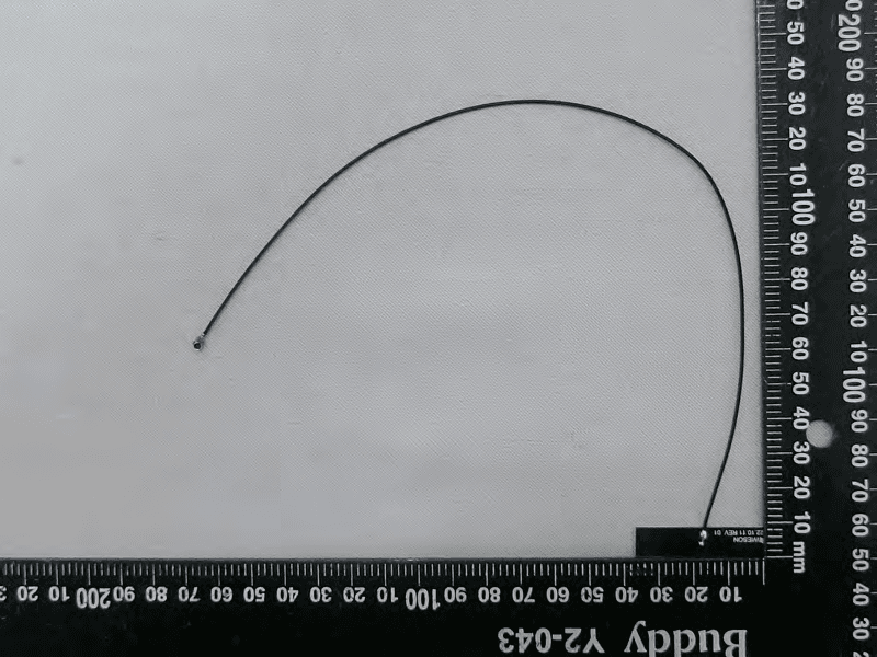
RAXAIOS7
Nov 08, 2023HEOS 7.0 Platform Module
Equipment Class
NII - Unlicensed National Information Infrastructure TX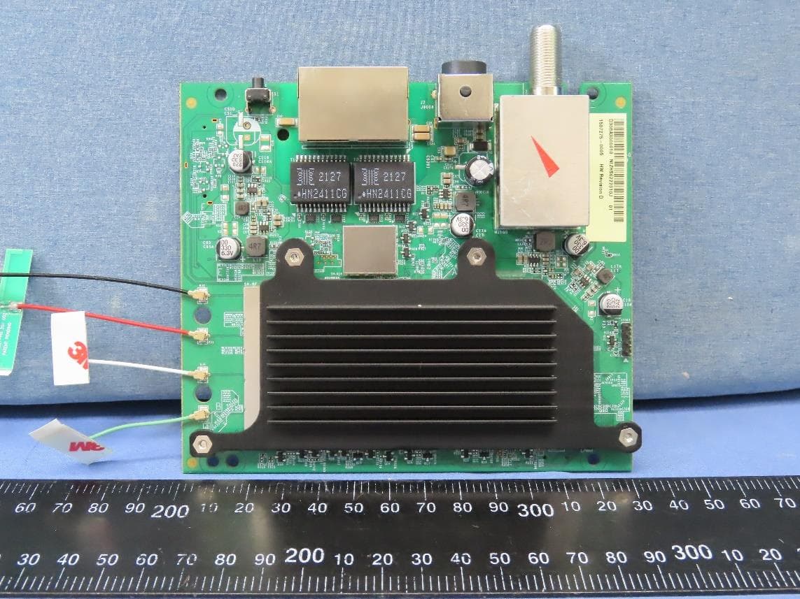
RAXWR3210
Jul 13, 2023Standalone Router
Equipment Class
DTS - Digital Transmission System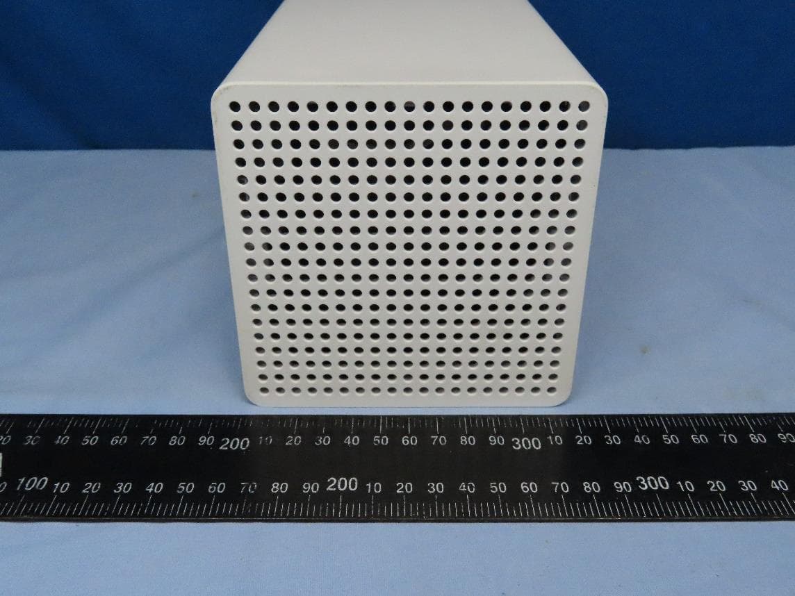
RAXWE7224443
Jan 11, 2023Verizon Wi-Fi Extender
Equipment Class
6PP - 15E 6 GHz Subordinate Indoor Device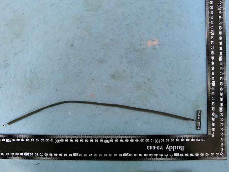
RAXAIOS65V
Nov 06, 2022HEOS 6.5 Platform Module
Equipment Class
DSS - Part 15 Spread Spectrum Transmitter