RAXWG4005FBARRICADETM 54Mbps g WIRELESS BROADBAND ROUTER
Arcadyan Technology Corporation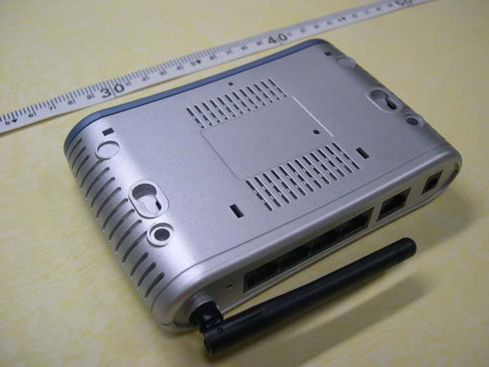
Click to zoom
Application Details
- Equipment Class
- DTS - Digital Transmission System
- Date of Grant
- Oct 25, 2005
- Application Purpose
- Original Equipment
- Date of Application
- Oct 25, 2005
- Equipment Note
- BARRICADETM 54Mbps g WIRELESS BROADBAND ROUTER
- Frequency Range
- 2412.00000000 - 2462.00000000
- Country
- Taiwan
Documents & Files
Document Text
Text extracted from the exhibit documents filed with the FCC. Open a document above to read the original.
Users Manual
38 Tesla Irvine, CA 92618 Phone: (949) 679-8000 Wireless Broadband Router User’s Guide From SMC’s line of award-winning connectivity solutions October 2005 R01 F/W 1.0 Information furnished is believed to be accurate and reliable. However, no responsibility is assumed by our company for its use, nor for any infringements of patents or other rights of third parties which may result from its use. No license is granted by implication or otherwise under any patent or patent rights of our company. We reserve the right to change specifications at any time without notice. Copyright © 2005 by SMC Networks, Inc. 38 Tesla Irvine, CA 92618 All rights reserved. Trademar ks: Product and company names are trademarks or registered trademarks of their respective holders. i LIMITED WARRANTY Limited Warranty Statement: SMC Networks, Inc. (“SMC”) warrants its products to be free from defects in workmanship and materials, under normal use and service, for the applicable warranty term. All SMC products carry a standard 90-day limited warranty from the date of purchase from SMC or its Authorized Reseller. SMC may, at its own discretion, repair or replace any product not operating as warranted with a similar or functionally equivalent product, during the applicable warranty term. SMC will endeavor to repair or replace any product returned under warranty within 30 days of receipt of the product. The standard limited warranty can be upgraded to a Limited Lifetime* warranty by registering new products within 30 days of purchase from SMC or its Authorized Reseller. Registration can be accomplished via the enclosed product registration card or online via the SMC web site. Failure to register will not affect the standard limited warranty. The Limited Lifetime warranty covers a product during the Life of that Product, which is defined as the period of time during which the product is an “Active” SMC product. A product is considered to be “Active” while it is listed on the current SMC price list. As new technologies emerge, older technologies become obsolete and SMC will, at its discretion, replace an older product in its product line with one that incorporates these newer technologies. At that point, the obsolete product is discontinued and is no longer an “Active” SMC product. A list of discontinued products with their respective dates of discontinuance can be found at: http://www.smc.com/index.cfm?action=customer_service_warranty. All products that are replaced become the property of SMC. Replacement products may be either new or reconditioned. Any replaced or repaired product carries either a 30-day limited warranty or the remainder of the initial warranty, whichever is longer. SMC is not responsible for any custom software or firmware, configuration information, or memory data of Customer contained in, stored on, or integrated with any products returned to SMC pursuant to any warranty. Products returned to SMC should have any customer-installed accessory or add-on components, such as expansion modules, removed prior to returning the product for replacement. SMC is not responsible for these items if they are returned with the product. Customers must contact SMC for a Return Material Authorization number prior to returning any product to SMC. Proof of purchase may be required. Any product returned to SMC without a valid Return Material Authorization (RMA) number clearly marked on the outside of the package will be returned to customer at customer’s expense. For warranty claims within North America, please call our toll-free customer support number at (800) 762-4968. Customers are responsible for all shipping charges from their facility to SMC. SMC is responsible for return shipping charges from SMC to customer. LIMITED WARRANTY ii WARRANTIES EXCLUSIVE: IF AN SMC PRODUCT DOES NOT OPERATE AS WARRANTED ABOVE, CUSTOMER’S SOLE REMEDY SHALL BE REPAIR OR REPLACEMENT OF THE PRODUCT IN QUESTION, AT SMC’S OPTION. THE FOREGOING WARRANTIES AND REMEDIES ARE EXCLUSIVE AND ARE IN LIEU OF ALL OTHER WARRANTIES OR CONDITIONS, EXPRESS OR IMPLIED, EITHER IN FACT OR BY OPERATION OF LAW, STATUTORY OR OTHERWISE, INCLUDING WARRANTIES OR CONDITIONS OF MERCHANTABILITY AND FITNESS FOR A PARTICULAR PURPOSE. SMC NEITHER ASSUMES NOR AUTHORIZES ANY OTHER PERSON TO ASSUME FOR IT ANY OTHER LIABILITY IN CONNECTION WITH THE SALE, INSTALLATION, MAINTENANCE OR USE OF ITS PRODUCTS. SMC SHALL NOT BE LIABLE UNDER THIS WARRANTY IF ITS TESTING AND EXAMINATION DISCLOSE THE ALLEGED DEFECT IN THE PRODUCT DOES NOT EXIST OR WAS CAUSED BY CUSTOMER’S OR ANY THIRD PERSON’S MISUSE, NEGLECT, IMPROPER INSTALLATION OR TESTING, UNAUTHORIZED ATTEMPTS TO REPAIR, OR ANY OTHER CAUSE BEYOND THE RANGE OF THE INTENDED USE, OR BY ACCIDENT, FIRE, LIGHTNING, OR OTHER HAZARD. LIMITATION OF LIABILITY: IN NO EVENT, WHETHER BASED IN CONTRACT OR TORT (INCLUDING NEGLIGENCE), SHALL SMC BE LIABLE FOR INCIDENTAL, CONSEQUENTIAL, INDIRECT, SPECIAL, OR PUNITIVE DAMAGES OF ANY KIND, OR FOR LOSS OF REVENUE, LOSS OF BUSINESS, OR OTHER FINANCIAL LOSS ARISING OUT OF OR IN CONNECTION WITH THE SALE, INSTALLATION, MAINTENANCE, USE, PERFORMANCE, FAILURE, OR INTERRUPTION OF ITS PRODUCTS, EVEN IF SMC OR ITS AUTHORIZED RESELLER HAS BEEN ADVISED OF THE POSSIBILITY OF SUCH DAMAGES. SOME STATES DO NOT ALLOW THE EXCLUSION OF IMPLIED WARRANTIES OR THE LIMITATION OF INCIDENTAL OR CONSEQUENTIAL DAMAGES FOR CONSUMER PRODUCTS, SO THE ABOVE LIMITATIONS AND EXCLUSIONS MAY NOT APPLY TO YOU. THIS WARRANTY GIVES YOU SPECIFIC LEGAL RIGHTS, WHICH MAY VARY FROM STATE TO STATE. NOTHING IN THIS WARRANTY SHALL BE TAKEN TO AFFECT YOUR STATUTORY RIGHTS. * SMC will provide warranty service for one year following discontinuance from the active SMC price list. Under the limited lifetime warranty, internal and external power supplies, fans, and cables are covered by a standard one-year warranty from date of purchase. SMC Networks, Inc. 38 Tesla Irvine, CA 92618 Warranty terms may differ according to geographic region. For compl…
Text truncated - open the document above for the full version.
Users Manual
TCP/IP CONFIGURATION 3-6 3. Type “IPCONFIG /RENEW” and press the Enter key. Verify that your IP Address is now 192.168.2.xxx, your Subnet Mask is 255.255.255.0 and your Default Gateway is 192.168.2.1. These values confirm that your Barricade is functioning correctly. 4. Type “EXIT” and press the Enter key to close the Command Prompt window. CONFIGURING THE CLIENT PC 3-7 Manual IP Configuration 1. Follow steps 1-4 in “DHCP IP Configuration” on page 3-3. 2. Select Use the following IP address. Enter an IP address based on the default network 192.168.2.x (where x is between 2 and 254), and use 255.255.255.0 for the subnet mask. Use 192.168.2.1 for the Default gateway field. 3. Select Use the following DNS server addresses. 4. Enter the IP address for the Barricade in the Preferred DNS server field. This automatically relays DNS requests to the DNS server(s) provided by your ISP. Otherwise, add a specific DNS server into the Alternate DNS Server field and click OK to close the dialog boxes. 5. Record the configured information in the following table. TCP/IP Configuration Setting IP Address____.____.____.____ Subnet Mask____.____.____.____ Preferred DNS Server____.____.____.____ Alternate DNS Server____.____.____.____ Default Gateway____.____.____.____ TCP/IP CONFIGURATION 3-8 Disable HTTP Proxy You need to verify that the “HTTP Proxy” feature of your web browser is disabled. This is so that your browser can view the Barricade’s HTML configuration pages. 1. To disable the proxy in Internet Explorer, click To o l s. Click Internet Options... and then the Connections tab, shown on the right. In the Local Area Network (LAN) settings section, click LAN Settings... to display the Local Area Network (LAN) Settings pop-up window below. 2. In the Proxy server section, ensure the Use a proxy server for your LAN (These settings will not apply to dial-up or VPN connections) check box is not ticked. 3. Click OK. CONFIGURING THE CLIENT PC 3-9 Windows XP DHCP IP Configuration 1. On the Windows desktop, click Start/Control Panel. 2. In the Control Panel window, click Network and Internet Connections. 3. The Network Connections window will open. Locate and double-click the Local Area Connection icon for the Ethernet adapter that is connected to the Barricade. 4. In the connection status screen, click Properties. TCP/IP CONFIGURATION 3-10 5. Double-click Internet Protocol (TCP/IP). 6. If Obtain an IP address automatically and Obtain DNS server address automatically are already selected, your computer is already configured for DHCP. If not, select these options now and click OK. CONFIGURING THE CLIENT PC 3-11 Obtain IP Settings From Your Barricade Now that you have configured your computer to connect to your Barricade, it needs to obtain new network settings. By releasing old DHCP IP settings and renewing them with settings from your Barricade, you can verify that you have configured your computer correctly. 1. On the Windows desktop, click Start/Programs/Accessories/ Command Prompt. 2. In the Command Prompt window, type “IPCONFIG /RELEASE” and press the Enter key. TCP/IP CONFIGURATION 3-12 3. Type “IPCONFIG /RENEW” and press the Enter key. Verify that your IP Address is now 192.168.2.xxx, your Subnet Mask is 255.255.255.0 and your Default Gateway is 192.168.2.1. These values confirm that your Barricade is functioning correctly. 4. Type “EXIT” and press the Enter key to close the Command Prompt window. Your computer is now configured to connect to the Barricade. CONFIGURING THE CLIENT PC 3-13 Manual IP Configuration 1. Follow steps 1-5 in “DHCP IP Configuration” on page 3-9. 2. Select Use the following IP Address. 3. Enter an IP address based on the default network 192.168.2.x (where x is between 2 and 254), and use 255.255.255.0 for the subnet mask. Use 192.168.2.1 for the Default gateway field. 4. Select Use the following DNS server addresses. 5. Enter the IP address for the Barricade in the Preferred DNS server field. This automatically relays DNS requests to the DNS server(s) provided by your ISP. Otherwise, add a specific DNS server into the Alternate DNS Server field and click OK to close the dialog boxes. 6. Record the configured information in the following table. TCP/IP Configuration Setting IP Address____.____.____.____ Subnet Mask____.____.____.____ Preferred DNS Server____.____.____.____ Alternate DNS Server____.____.____.____ Default Gateway____.____.____.____ TCP/IP CONFIGURATION 3-14 Disable HTTP Proxy You need to verify that the “HTTP Proxy” feature of your web browser is disabled. This is so that your browser can view the Barricade’s HTML configuration pages. 1. To disable the proxy in Internet Explorer, click To o l s. Click Internet Options... and then the Connections tab, shown on the right. In the Local Area Network (LAN) settings section, click LAN Settings... to display the Local Area Network (LAN) Settings pop-up window below. 2. In the Proxy server section, ensure the Use a proxy server for your LAN (These settings will not apply to dial-up or VPN connections) check box is not ticked. 3. Click OK. CONFIGURING THE CLIENT PC 3-15 Configuring Your Macintosh Computer You may find that the instructions here do not exactly match your operating system. This is because these steps and screen shots were created using Mac OS 10.2. Mac OS 7.x and above are similar, but may not be identical to Mac OS 10.2. Follow these instructions: 1. Pull down the Apple Menu. Click System Preferences. 2. Double-click the Network icon in the Systems Preferences window. CONFIGURING YOUR MACINTOSH COMPUTER 3-16 3. If Using DHCP Server is already selected in the Configure field, your computer is already configured for DHCP. If not, select this option. 4. Your new settings are shown in the TCP/IP tab. Verify that your IP Address is now 192.168.2.xxx, your Subnet Mask is 255.255.255.0 and your Default Gateway is 192.168.2.1. These values confirm that your Barricade is functioning. 5. Close the Network window. Now your…
Text truncated - open the document above for the full version.
Users Manual
HOME NETWORK SETTINGS 4-21 PPTP The PPTP screen displays the IP Address, Subnet Mask and Default Gateway of your Barricade. Enter the User ID and Password assigned by your ISP in the appropriate fields. Enter the Idle Time Out for the Internet connection. This is the period of time for which the connection to the Internet is maintained during inactivity. The default setting is 10 minutes. If your ISP charges you by the minute, you should change the Idle Time Out to one minute. After the Idle Time Out has expired, set the action you wish the Barricade to take. You can tell the device to connect manually or automatically as soon as you try to access the Internet again, or to keep the session alive. Click Save Settings to proceed, or Cancel to change your settings. CONFIGURING THE BARRICADE 4-22 Static IP If your Service Provider has assigned a fixed IP address, enter the assigned IP address, subnet mask and the gateway address on this screen. Click Save Settings to proceed, or Cancel to change your settings. HOME NETWORK SETTINGS 4-23 Wireless The Barricade can be quickly configured for roaming clients by setting the Service Set Identifier (SSID) and channel number. It supports data encryption and client filtering. To use the wireless feature, check the Enable check box and click Save Settings. After clicking Save Settings, you will be asked to log in again. See “Security” on page 4-27 for details on how to configure wireless security. CONFIGURING THE BARRICADE 4-24 Channel and SSID Enter your wireless network settings on this screen. You must specify a common radio channel and SSID (Service Set ID) to be used by the Barricade and all of its wireless clients. Be sure you configure all of its clients to the same value. For security purposes, you should change the default SSID immediately. ParameterDescription Wireless Network Name (SSID) The Service Set ID (SSID) is the name of your wireless network. The SSID must be the same on the Barricade and all of its wireless clients. (Default: SMC) Broadcast Wireless Network Name Enable or disable the broadcasting of the SSID. If you disable broadcast of the SSID, only devices that have the correct SSID can connect. This nullifies the wireless network “discovery” feature of some products such as Windows XP. (Default: Enable) Wireless ModeThis device supports the following modes; 11g only, 11b only, 11b/g mixed mode, Super G-Dynamic Turbo and Super G-Static Turbo. (Default: 11b/g mixed mode) HOME NETWORK SETTINGS 4-25 Wi-Fi Channel Number The radio channel used by the Barricade and its clients to communicate with each other. This channel must be the same on the Barricade and all of its wireless clients. The Barricade will automatically assign itself a radio channel, or you may select one manually. (Default: 6) Extend RangeExtends the range of the Barricade. (Default: Disable) ParameterDescription CONFIGURING THE BARRICADE 4-26 WDS The Wireless Distribution System (WDS) provides a means to extend the range of a Wireless Local Area Network (WLAN). WDS allows the Barricade to establish a direct link to other wireless base stations and allows clients to roam freely within the area covered by the WDS. To carry out a site survey of available wireless base stations, click Scan. ParameterDescription SSIDThe Service Set ID (SSID) is the name of your wireless network. The SSID must be the same on the Barricade and all of its wireless clients. ChannelThis device supports the following modes 11g only, 11b only, and 11b/g mixed mode. MAC AddressThe media access control address (MAC address) is a unique identifier attached to each wireless base station. SecurityDisplays the security mechanism in use. Enable WDSEnables the WDS feature. When enabled, up to 4 WDS links can be set by specifying their Wireless MAC addresses in the MAC address table. Make sure the same channel is in use on all devices. (Default: Disable) SECURITY 4-27 Security The first menu item in the Security section is Firewall. The Barricade provides a stateful inspection firewall which is designed to protect against Denial of Service (DoS) attacks when activated. Its purpose is to allow a private local area network (LAN) to be securely connected to the Internet. The second menu item is Wireless. This section allows you to configure wireless security settings according to your environment and the privacy level required. To configure your firewall settings, click Firewall in the left-hand menu. CONFIGURING THE BARRICADE 4-28 Firewall The Barricade’s firewall inspects packets at the application layer, maintains TCP and UDP session information including time-outs and the number of active sessions, and provides the ability to detect and prevent certain types of network attacks. Network attacks that deny access to a network device are called Denial-of- Service (DoS) attacks. DoS attacks are aimed at devices and networks with a connection to the Internet. Their goal is not to steal information, but to disable a device or network so users no longer have access to network resources. The Barricade protects against the following DoS attacks: IP Spoofing, Land Attack, Ping of Death, IP with zero length, Smurf Attack, UDP port loopback, Snork Attack, TCP null scan, and TCP SYN flooding. (See “Intrusion Detection” on page 4-35 for details.) The firewall does not significantly affect system performance, so we advise leaving it enabled to protect your network. Enable the firewall feature, and click Save Settings to proceed. SECURITY 4-29 Schedule Rule The first item listed in the Firewall section is Schedule Rule. You may filter Internet access for local clients based on rules. You may filter Internet access for local clients based on rules. Each access control rule may be activated at a scheduled time. First, define the schedule on the Schedule Rule page, then apply the rule on the Access Control page. To add a new rule, click Add Schedule Rule. Proceed to the following page. CONFIGURING THE BARRICADE 4-30 Edit …
Text truncated - open the document above for the full version.
Users Manual
CONFIGURING THE BARRICADE 4-38 Stateful Packet Inspection EnabledThis option allows you to select different application types that are using dynamic port numbers. If you wish to use Stateful Packet Inspection (SPI) for blocking packets, click on the Yes radio button in the “Enable SPI and Anti-DoS firewall protection” field and then check the inspection type that you need, such as Packet Fragmentation, TCP Connection, UDP Session, FTP Service and TFTP Service. It is called a “stateful” packet inspection because it examines the contents of the packet to determine the state of the communication; i.e., it ensures that the stated destination computer has previously requested the current communication. This is a way of ensuring that all communications are initiated by the recipient computer and are taking place only with sources that are known and trusted from previous interactions. In addition to being more rigorous in their inspection of packets, stateful inspection firewalls also close off ports until a connection to the specific port is requested. When particular types of traffic are checked, only the particular type of traffic initiated from the internal LAN will be allowed. For example, if the user only checks FTP Service in the Stateful Packet Inspection section, all incoming traffic will be blocked except for FTP connections initiated from the local LAN. When hackers attempt to enter your network, we can alert you by email Your E-mail Address Enter your email address. SMTP Server Address Enter your SMTP server address (usually the part of the email address following the “@” sign). POP3 Server Address Enter your POP3 server address (usually the part of the email address following the “@” sign). User NameEnter your email account user name. ParameterDefaults Description SECURITY 4-39 PasswordEnter your email account password. Connection Policy Fragmentation half-open wait 10 secsConfigures the number of seconds that a packet state structure remains active. When the timeout value expires, the router drops the unassembled packet, freeing that structure for use by another packet. TCP SYN wait30 secsDefines how long the software will wait for a TCP session to reach an established state before dropping the session. TCP FIN wait5 secsSpecifies how long a TCP session will be managed after the firewall detects a FIN-exchange. TCP connection idle timeout 3600 secs (1 hour) The length of time for which a TCP session will be managed if there is no activity. UDP session idle timeout 30 secsThe length of time for which a UDP session will be managed if there is no activity. DoS Detect Criteria Total incomplete TCP/UDP sessions HIGH 300 sessions Defines the rate of new unestablished sessions that will cause the software to start deleting half-open sessions. Total incomplete TCP/UDP sessions LOW 250 sessions Defines the rate of new unestablished sessions that will cause the software to stop deleting half-open sessions. Incomplete TCP/UDP sessions (per min.) HIGH 250 sessions Maximum number of allowed incomplete TCP/UDP sessions per minute. Incomplete TCP/UDP sessions (per min.) LOW 200 sessions Minimum number of allowed incomplete TCP/UDP sessions per minute. Maximum incomplete TCP/UDP sessions number from same host 10 sessions Maximum number of incomplete TCP/UDP sessions from the same host. ParameterDefaults Description CONFIGURING THE BARRICADE 4-40 Note:We do not recommend modifying the default parameters shown above. Click Save Settings to proceed, or Cancel to change your settings. Incomplete TCP/UDP sessions detect sensitive time period 300 msecs Length of time before an incomplete TCP/UDP session is detected as incomplete. Maximum half-open fragmentation packet number from same host 30 sessions Maximum number of half-open fragmentation packets from the same host. Half-open fragmentation detect sensitive time period 1 secLength of time before a half-open fragmentation session is detected as half-open. Flooding cracker block time 300 secsLength of time from detecting a flood attack to blocking the attack. ParameterDefaults Description SECURITY 4-41 DMZ If you have a client PC that cannot run an Internet application properly from behind the firewall, you can open the client up to unrestricted two-way Internet access. Enter the IP address of a DMZ (Demilitarized Zone) host on this screen. Adding a client to the DMZ may expose your local network to a variety of security risks, so only use this option as a last resort. CONFIGURING THE BARRICADE 4-42 Wireless The Barricade can be quickly configured for roaming clients by setting the Service Set Identifier (SSID) and channel number. It supports data encryption and client filtering. To use the wireless feature, check the Enable check box and click Save Settings. To begin configuring your wireless security settings, click Wireless Encryption. SECURITY 4-43 Wireless Encryption The Barricade can transmit your data securely over a wireless network. Matching security mechanisms must be set up on your Barricade and your wireless client devices. Select the most suitable security mechanism from the drop-down list on this screen. Click Save Settings to proceed, or Cancel to change your settings. ParameterDescription No WEP, No WPA/WPA2Disables all wireless security. To make it easier to set up your wireless network, we recommend enabling this setting initially. By default, wireless security is disabled. WEP OnlyOnce you have your wireless network in place, the minimum security we recommend is to enable the legacy security standard, Wired Equivalent Privacy (WEP). See “WEP” on page 4-45. WPA/WPA2 OnlyFor maximum wireless security, you should enable the WPA/WPA2 option. See “WPA/WPA2” on page 4-47. CONFIGURING THE BARRICADE 4-44 Access Control For a more secure wireless network you can specify that only certain wireless clients can connect to the Barricade. Up to 32 MAC addresses can be added to the MAC Filtering Table. When enabled, all registered MAC addresses ar…
Text truncated - open the document above for the full version.
Users Manual
CONFIGURING THE BARRICADE 4-54 Virtual Server Using this feature, you can put PCs with public IPs and PCs with private IPs in the same LAN area. If you configure the Barricade as a virtual server, remote users accessing services such as web or FTP at your local site via public IP addresses can be automatically redirected to local servers configured with private IP addresses. In other words, depending on the requested service (TCP/UDP port number), the Barricade redirects the external service request to the appropriate server (located at another internal IP address). For example, if you set Type/Public Port to TCP/80 (HTTP or web) and the Private IP/Port to 192.168.2.2/80, then all HTTP requests from outside users will be transferred to 192.168.2.2 on port 80. Therefore, by just entering the IP address provided by the ISP, Internet users can access the service they need at the local address to which you redirect them. The more common TCP service ports include: HTTP: 80, FTP: 21, Telnet: 23, and POP3: 110. Click All known port number for more information about public service ports. ADVANCED SETTINGS 4-55 Special Applications Some applications, such as Internet gaming, videoconferencing, Internet telephony and others, require multiple connections. These applications cannot work with Network Address Translation (NAT) enabled. If you need to run applications that require multiple connections, use the following screen to specify the additional public ports to be opened for each application. Click the List of well known special applications link for more information. Specify the public port number normally associated with an application in the Trigger Port field. Set the protocol type to TCP or UDP, then enter the ports that the application requires. The ports may be in the format of a single port, or in a range, e.g., 72-96, or a combination of both. CONFIGURING THE BARRICADE 4-56 Popular applications requiring multiple ports are listed in the Popular Applications field. From the drop-down list, choose the application and then choose a row number to copy this data into. Note:Choosing a row that already contains data will overwrite the current settings. For a full list of ports and the services that run on them, see www.iana.org/assignments/port-numbers ADVANCED SETTINGS 4-57 NAT Mapping Table This page displays the current NAPT (Network Address Port Translation) address mappings. The NAT address mappings are listed 20 lines per page, click the control buttons to move forwards and backwards. As the NAT mapping is dynamic, a Refresh button is provided to refresh the NAT Mapping Table with the most updated values. The content of the NAT Mapping Table is described as follows: •Protocol - protocol of the flow. •Local IP - local (LAN) host’s IP address for the flow. •Local Port - local (LAN) host’s port number for the flow. •Pseudo IP - translated IP address for the flow. •Pseudo Port - translated port number for the flow. •Peer IP - remote (WAN) host’s IP address for the flow. •Peer Port - remote (WAN) host’s port number for the flow. CONFIGURING THE BARRICADE 4-58 Maintenance Use the Maintenance menu to back up the current settings, to restore previously saved settings, or to restore the factory default settings. Configuration Tools Check Backup Wireless Router Configuration and click NEXT to save your Barricade’s configuration to a file named config.bin on your PC. You can then check the Restore from saved Configuration file (SMCWBR14-G2_backup.bin) radio button and click NEXT to restore the saved backup configuration file. To restore the factory settings, check Restore Wireless Router to Factory Defaults and click NEXT. You will be asked to confirm your decision. MAINTENANCE 4-59 Firmware Upgrade Use this screen to update the firmware to the latest version. Go to www.smc.com to find the latest firmware. Download the firmware to your hard drive first. Click Browse... to locate the saved file. After locating the new firmware file, click BEGIN UPGRADE. Follow the instructions to complete the upgrade. After restarting, check the Status page to make sure the device is running the new code. CONFIGURING THE BARRICADE 4-60 Reset Perform a reset from this screen. To perform a system reset, click the Reboot Wireless Router button in the screen above. The configurations that you have set previously will not be changed back to the factory default settings. Note:You may also use the blue Reset button on the rear panel of the Barricade to perform a reset. Push for one second to perform a reboot. All of your settings will remain upon restarting. Push for six seconds to return the Barricade to factory default settings. SYSTEM 4-61 System This section includes all the basic configuration tools for the Barricade, such as time settings, password settings, and remote management. Time Settings Set the time zone and time server for the Barricade. This information is used for log entries and client access control. •Set Time Zone Select your time zone from the drop-down list •Enable Daylight Savings Check Enable Daylight Savings, and set the start and end dates if your area requires daylight savings. •Set Date and Time Manually For manually setting the date and time, configure the date and time by selecting the options from the drop-down list. CONFIGURING THE BARRICADE 4-62 •Enable Automatic Time Server Maintenance Check Enable Automatic Time Server Maintenance to automatically maintain the Barricade’s system time by synchronizing with a public time server over the Internet. •Configure Time Server (NTP): Configure two different time servers by selecting the options in the Primary Server and Secondary Server fields. SYSTEM 4-63 Password Settings Use this page to restrict access based on a password. For security you should assign one before exposing the Barricade to the Internet. Passwords can contain from 3 to12 alphanumeric characters and are case sensitive. Note:If your password is lost, or you cannot gain access to t…
Text truncated - open the document above for the full version.
Contact Information
Applicant
Simon Liu(Manager)
Test Firm
SPORTON International IncKathy Lin
Technical Specifications
| # | Rule Parts | Frequency Range | Power Output |
|---|---|---|---|
| 1 | 15C | 2.41 GHz - 2.46 GHz | 174.00 mW |
Other Applications from Arcadyan Technology Corporation
RAXWE6204430
Jan 27, 2024Wi-Fi Extender
Equipment Class
DTS - Digital Transmission System
RAXAIOS7
Nov 08, 2023HEOS 7.0 Platform Module
Equipment Class
NII - Unlicensed National Information Infrastructure TX
RAXWR3210
Jul 13, 2023Standalone Router
Equipment Class
DTS - Digital Transmission System
RAXWE7224443
Jan 11, 2023Verizon Wi-Fi Extender
Equipment Class
6PP - 15E 6 GHz Subordinate Indoor Device
RAXAIOS65V
Nov 06, 2022HEOS 6.5 Platform Module
Equipment Class
DSS - Part 15 Spread Spectrum Transmitter