RAXWG6005AARCEZ-Stream Universal 2.4GHz/5GHz Cable/DSL Router
Arcadyan Technology Corporation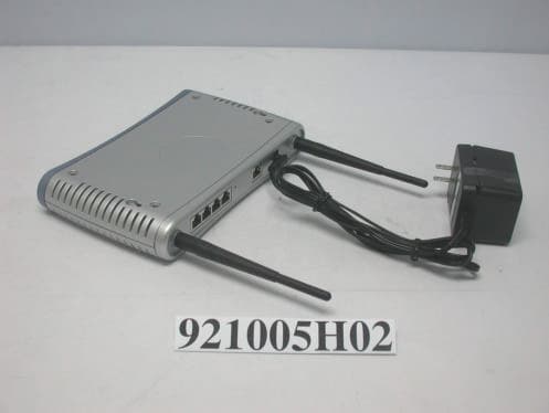
Click to zoom
Application Details
- Equipment Class
- NII - Unlicensed National Information Infrastructure TX
- Date of Grant
- Dec 21, 2003
- Application Purpose
- Original Equipment
- Date of Application
- Dec 21, 2003
- Equipment Note
- EZ-Stream Universal 2.4GHz/5GHz Cable/DSL Router
- Frequency Range
- 5725.00000000 - 5825.00000000
- Country
- Taiwan
Documents & Files
Document Text
Text extracted from the exhibit documents filed with the FCC. Open a document above to read the original.
Users Manual
38 Tesla Irvine, CA 92618 Phone: (949) 679-8000 EZ-Stream Universal 2.4GHz/5GHz Wireless Cable/DSL Broadband Router User Guide From SMC’s EZ-Stream line of Broadband Routers October 2003 Revision No: R01 COPYRIGHT Information furnished by SMC Networks, Inc. (SMC) is believed to be accurate and reliable. However, no responsibility is assumed by SMC for its use, nor for any infringements of patents or other rights of third parties which may result from its use. No license is granted by implication or otherwise under any patent or patent rights of SMC. SMC reserves the right to change specifications at any time without notice. Copyright © 2003 by SMC Networks, Inc. 38 Tesla Irvine, CA 92618 All rights reserved. Trademarks: SMC is a registered trademark; EZ-Stream and Barricade is a trademark of SMC Networks, Inc. Other product and company names are trademarks or registered trademarks of their respective holders. i COMPLIANCES Federal Communication Commission Interference Statement This equipment has been tested and found to comply with the limits for a Class B digital device, pursuant to Part 15 of the FCC Rules. These limits are designed to provide reasonable protection against harmful interference in a residential installation. This equipment generates, uses and can radiate radio frequency energy and, if not installed and used in accordance with the instructions, may cause harmful interference to radio communications. However, there is no guarantee that interference will not occur in a particular installation. If this equipment does cause harmful interference to radio or television reception, which can be determined by turning the equipment off and on, the user is encouraged to try to correct the interference by one of the following measures: • Reorient or relocate the receiving antenna • Increase the separation between the equipment and receiver • Connect the equipment into an outlet on a circuit different from that to which the receiver is connected • Consult the dealer or an experienced radio/TV technician for help This device complies with Part 15 of the FCC Rules. Operation is subject to the following two conditions: (1) This device may not cause harmful interference, and (2) this device must accept any interference received, including interference that may cause undesired operation. FCC Caution: Any changes or modifications not expressly approved by the party responsible for compliance could void the user's authority to operate this equipment. IMPORTANT NOTE: FCC Radiation Exposure Statement This equipment complies with FCC radiation exposure limits set forth for an uncontrolled environment. This equipment should be installed and operated with a minimum distance of 20 centimeters (8 inches) between the radiator and your body. This transmitter must not be co-located or operating in conjunction with any other antenna or transmitter. Compliances ii EC Conformance Declaration - Class B SMC contact for these products in Europe is: SMC Networks Europe, Edificio Conata II, Calle Fructuós Gelabert 6-8, 2 o , 4 a , 08970 - Sant Joan Despí, Barcelona, Spain. This information technology equipment complies with the requirements of the Council Directive 89/336/EEC on the Approximation of the laws of the Member States relating to Electromagnetic Compatibility and 73/23/EEC for electrical equipment used within certain voltage limits and the Amendment Directive 93/68/ EEC. For the evaluation of the compliance with these Directives, the following standards were applied: RFI Emission: * Limit class B according to EN 55022:1998 * Limit class B for harmonic current emission according to EN 61000-3-2/ 1995 * Limitation of voltage fluctuation and flicker in low-voltage supply system according to EN 61000-3-3/1995 Immunity: * Product family standard according to EN 55024:1998 * Electrostatic Discharge according to EN 61000-4-2:1995 (Contact Discharge: ±4 kV, Air Discharge: ±8 kV) * Radio-frequency electromagnetic field according to EN 61000-4-3: 1996 (80 - 1000 MHz with 1 kHz AM 80% Modulation: 3 V/m) * Electrical fast transient/burst according to EN 61000-4-4:1995 (AC/DC power supply: ±1 kV, Data/Signal lines: ±0.5 kV) * Surge immunity test according to EN 61000-4-5:1995 (AC/DC Line to Line: ±1 kV, AC/DC Line to Earth: ±2 kV) * Immunity to conducted disturbances, Induced by radio-frequency fields: EN 61000-4-6:1996(0.15 - 80 MHz with 1 kHz AM 80% Modulation: 3V/m) * Power frequency magnetic field immunity test according to EN 61000-4-8:1993(1 A/m at frequency 50 Hz) * Voltage dips, short interruptions and voltage variations immunity test according to EN 61000-4-11:1994 (>95% Reduction @10 ms, 30% Reduction @500 ms, >95% Reduction @5000 ms) LVD:* EN60950 (A1/1992; A2/1993; A3/1993; A4/1995; A11/1997) MDD:*IEC 60601-1 Compliances iii Industry Canada - Class B This digital apparatus does not exceed the Class B limits for radio noise emissions from digital apparatus as set out in the interference-causing equipment standard entitled “Digital Apparatus,” ICES-003 of the Department of Communications. Cet appareil numérique respecte les limites de bruits radioélectriques applicables aux appareils numériques de Classe B prescrites dans la norme sur le matériel brouilleur: “Appareils Numériques,” NMB-003 édictée par le ministère des Communications. Safety Compliance Underwriters Laboratories Compliance Statement Important! Before making connections, make sure you have the correct cord set. Check it (read the label on the cable) against the following: The unit automatically matches the connected input voltage. Therefore, no additional adjustments are necessary when connecting it to any input voltage within the range marked on the rear panel. Operating VoltageCord Set Specifications 120 VoltsUL Listed/CSA Certified Cord Set Minimum 18 AWG Type SVT or SJT three conductor cord Maximum length of 15 feet Parallel blade, grounding type attachment plug rated 15 A, 125 V 240 Volts (Europe only)Cord Set with H05VV-F cord ha…
Text truncated - open the document above for the full version.
External Photos
Page 1 CONSTRUCTION PHOTOS OF EUT Page 2
ID Label/Location Info
(Fig. 1) FCC ID: RAXWG6005AARC LABEL LOCATION Label
Internal Photos
Page 1 CONSTRUCTION PHOTOS OF EUT Page 2 Page 3 Page 4 Page 5 Page 6 Page 7
Operational Description
FCC ID: RAXWG6005AARC ADT No. RF921005H02 Technical Description The transmitter of the EUT is powered by AC adapter. The antenna is is Dual Band Omni-directional Antenna with I-Pex MHF-20278-111R-18 connector. This device is a EZ-Stream Universal 2.4GHz/5GHz Wireless Cable/DSL Broadband Router operates in both the 5GHz and 2.4GHz bands. For more detailed instruction, please take a look at the user’s manual. FCC 15.407(c) states : The device shall automatically discontinue transmission in case of either absence of information to transmit or operational failure. These provisions are not intended to preclude the transmission of control or signaling information or the use of repetitive codes used by certain digital technologies to complete frame or burst intervals. Applicants shall include in their application for equipment authorization a description of hoe this requirement is met. Data transmission is always initiated by software, which is then pass down through the MAC, through the digital and analog baseband, and finally to the RF chip. Several special packets (ACKs, CTS, PSPoll, etc...) are initiated by the MAC. There are the only ways the digital baseband portion will turn on the RF transmitter, which it then turns off at the end of the packet. Therefore, the transmitter will be on only while one of the aforementioned packets are being transmitted.
RF Exposure Info
FCC ID: RAXWG6005AARC ADT No.: RF921005H021 RF EXPOSURE REPORT REPORT NO.: RF921005H02 MODEL NO.: SMC2304WBR-AG ACCORDING: FCC Guidelines for Human Exposure IEEE C95.1 APPLICANT: Arcadyan Technology Corporation ADDRESS: 4F, No. 9, Park Avenue II, Science-based Industrial Park, Hsinchu 300, Taiwan, R.O.C. ISSUED BY: Advance Data Technology Corporation LAB LOCATION: 47 14th Lin, Chiapau Tsun, Linko, Taipei, Taiwan, R.O.C. Lab Code: 200376-0 FCC ID: RAXWG6005AARC ADT No.: RF921005H022 RF Exposure Measurement 1. Introduction In this document, we try to prove the safety of radiation harmfulness to the human body for our product. The limit for Maximum Permissible Exposure (MPE) specified in FCC 1.1310 is followed. The Gain of the antenna used in this product is measured in a Fully Anechoic Chamber (FAC) calibrated for antenna measurement in ADT, and also the maximum total power input to the antenna is measured. Through the Friis transmission formula and the maximum gain of the antenna, we can calculate the distance, away from the product, where the limit of MPE is reached. Although the Friis transmission formula is a far field assumption, the calculated result of that is an over-prediction for near field power density. We will take that as the worst case to specify the safety range. 2. RF Exposure Limit According to FCC 1.1310: The criteria listed in the following table shall be used to evaluate the environmental impact of human exposure to radio-frequency (RF) radiation as specified in 1.1307(b) LIMITS FOR MAXIMUM PERMISSIBLE EXPOSURE (MPE) Frequency Range (MHz) Electric Field Strength (V/m) Magnetic Field Strength (A/m) Power Density (mW/cm 2 ) Average Time (minutes) (A)Limits For Occupational / Control Exposures 300-1500......F/3006 1500-100,000......56 (B)Limits For General Population / Uncontrolled Exposure 300-1500......F/15006 1500-100,000......1.030 F = Frequency in MHz FCC ID: RAXWG6005AARC ADT No.: RF921005H023 3. Friis Formula Friis transmission formula : Pd = (Pout*G) / (4*pi*r 2 ) where Pd = power density in mW/cm 2 Pout = output power to antenna in mW G = gain of antenna in linear scale Pi = 3.1416 R = distance between observation point and center of the radiator in cm Pd is the limit of MPE, 1 mW/cm 2 . If we know the maximum Gain of the antenna and the total power input to the antenna, through the calculation, we will know the MPE value at distance 20cm. Ref. : David K. Cheng, Field and Wave Electromagnetics, Second Edition, Page 640, Eq. (11-133). 4 EUT Operating condition The software provided by Manufacturer enabled the EUT to transmit and receive data at lowest, middle and highest channel individually. 5. Classification This device is not fixed inside the host equipment, it is connected with host through wire. So it is easy to be re-located in the place where at least 20 cm far away from the body of the user. Warning statement to the user for keeping at least 20cm or more separation distance with the antenna should be included in users manual. So, this device is classified as Mobile Device. FCC ID: RAXWG6005AARC ADT No.: RF921005H024 6 Test Results 6.1 Antenna Gain The maximum Gain measured in Fully Anechoic Chamber are as below: 1. 1.82dBi or 1.52(numeric) for 2.45GHz 2. 3.67dBi or 2.328(numeric) for 5.0GHz 3. 4.28dBi or 2.679(numeric) for 5.25GHz 4. 3.48dBi or 2.228(numeric) for 5.75GHz. 6.2 Output Power Into Antenna & RF Exposure value at distance 20cm: For Part 802.11b: Channel Channel Frequency (MHz) Output Power to Antenna (mW) Power Density (mW/cm 2 ) Limit of Power Density (mW/cm 2 ) 1241279.6160.024081.0 6243783.3680.025221.0 11246276.7360.023211.0 For Part 802.11g: Channel Channel Frequency (MHz) Output Power to Antenna (mW) Power Density (mW/cm 2 ) Limit of Power Density (mW/cm 2 ) 1241270.9580.021461.0 6243772.7780.022021.0 11246271.4500.021611.0 For 802.11a (5GHz Band): Normal Mode : Channel Channel Frequency (MHz) Output Power to Antenna (mW) Power Density (mW/cm 2 ) Limit of Power Density (mW/cm 2 ) 1518029.2420.013541.0 4524044.5660.020641.0 5526086.2980.046001.0 8532054.8280.029221.0 9574573.9610.032791.0 12580565.7660.029161.0
Test Report
FCC ID: RAXWG6005AARC Report No.: RF921005H021Issued:Dec. 11, 2003 FCC TEST REPORT REPORT NO.: RF921005H02 MODEL NO.: SMC2304WBR-AG RECEIVED: Oct. 06, 2003 TESTED: Nov. 12 to Dec. 9, 2003 APPLICANT: Arcadyan Technology Corporation ADDRESS: 4F, No. 9, Park Avenue II, Science-based Industrial Park, Hsinchu 300, Taiwan, R.O.C. ISSUED BY: Advance Data Technology Corporation LAB LOCATION: No. 81-1, Lu Liao Keng, 9 Ling, Wu Lung Tsuen, Chiung Lin Hsiang, Hsin Chu Hsien, Taiwan, R.O.C. This test report consists of 123 pages in total. It may be duplicated completely for legal use with the approval of the applicant. It should not be reproduced except in full, without the written approval of our laboratory. The client should not use it to claim product endorsement by NVLAP or any government agencies. The test results in the report only apply to the tested sample. 0536 ILAC MRA Lab Code: 200376-0 FCC ID: RAXWG6005AARC Report No.: RF921005H022Issued:Dec. 11, 2003 Table of Contents 1.CERTIFICATION............................................................................................................5 2.SUMMARY OF TEST RESULTS.....................................................................................6 3.GENERAL INFORMATION.............................................................................................8 3.1GENERAL DESCRIPTION OF EUT................................................................................8 3.2DESCRIPTION OF TEST MODES................................................................................10 3.3GENERAL DESCRIPTION OF APPLIED STANDARDS..................................................11 3.4DESCRIPTION OF SUPPORT UNITS...........................................................................12 4.TEST TYPES AND RESULTS (For Part 802.11b)...........................................................14 4.1CONDUCTED EMISSION MEASUREMENT..................................................................14 4.1.1LIMITS OF CONDUCTED EMISSION MEASUREMENT.................................................14 4.1.2TEST INSTRUMENTS..................................................................................................14 4.1.3TEST PROCEDURES..................................................................................................15 4.1.4DEVIATION FROM TEST STANDARD..........................................................................15 4.1.5TEST SETUP...............................................................................................................16 4.1.6EUT OPERATING CONDITIONS..................................................................................16 4.1.7TEST RESULTS (A)- DSSS..........................................................................................17 4.1.8TEST RESULTS (B)- OFDM.........................................................................................19 4.2Radiated Emission Measurement..................................................................................21 4.2.1LIMITS OF RADIATED EMISSION MEASUREMENT.....................................................21 4.2.2TEST INSTRUMENTS..................................................................................................22 4.2.3TEST PROCEDURES..................................................................................................23 4.2.4DEVIATION FROM TEST STANDARD..........................................................................23 4.2.5TEST SETUP...............................................................................................................24 4.2.6EUT OPERATING CONDITIONS..................................................................................24 4.2.7TEST RESULTS...........................................................................................................25 4.36dB BANDWIDTH MEASUREMENT.............................................................................32 4.3.1LIMITS OF 6dB BANDWIDTH MEASUREMENT............................................................32 4.3.2TEST INSTRUMENTS..................................................................................................32 4.3.3TEST PROCEDURE....................................................................................................33 4.3.4DEVIATION FROM TEST STANDARD..........................................................................33 4.3.5TEST SETUP...............................................................................................................33 4.3.6EUT OPERATING CONDITIONS..................................................................................33 4.3.7TEST RESULTS (A).....................................................................................................34 4.3.8TEST RESULTS (B).....................................................................................................38 4.4MAXIMUM PEAK OUTPUT POWER.............................................................................42 4.4.1LIMITS OF MAXIMUM PEAK OUTPUT POWER MEASUREMENT.................................42 4.4.2INSTRUMENTS...........................................................................................................42 4.4.3TEST PROCEDURES..................................................................................................43 4.4.4TEST SETUP...............................................................................................................43 4.4.5EUT OPERATING CONDITIONS..................................................................................43 4.4.6TEST RESULTS (A).....................................................................................................44 FCC ID: RAXWG6005AARC Report No.: RF921005H023Issued:Dec. 11, 2003 4.4.7TEST RESULTS (B).....................................................................................................44 4.5POWER SPECTRAL DENSITY MEASUREMENT..........................................................4…
Text truncated - open the document above for the full version.
Test Report
FCC ID: RAXWG6005AARC Report No.: RF921005H0251Issued:Dec. 11, 2003 4.5.8 TEST RESULTS(B) EUT EZ-Stream Universal 2.4GHz/5GHz Wireless Cable/DSL Broadband Router MODEL SMC2304WBR-AG INPUT POWER (SYSTEM) 120Vac, 60Hz ENVIRONMENTAL CONDITIONS 27deg. C, 58RH, 980 hPa TESTED BY Tony Chen CHANNEL NUMBER CHANNEL FREQUENCY (MHz ) RF POWER LEVEL IN 3 kHz BW (dBm) MAXIMUM LIMIT (dBm) PASS/FAIL 12412-0.398PASS 62437-0.658PASS 112462-0.198PASS FCC ID: RAXWG6005AARC Report No.: RF921005H0252Issued:Dec. 11, 2003 CH1 FCC ID: RAXWG6005AARC Report No.: RF921005H0253Issued:Dec. 11, 2003 CH6 FCC ID: RAXWG6005AARC Report No.: RF921005H0254Issued:Dec. 11, 2003 CH11 FCC ID: RAXWG6005AARC Report No.: RF921005H0255Issued:Dec. 11, 2003 4.6 BAND EDGES MEASUREMENT 4.6.1 LIMITS OF BAND EDGES MEASUREMENT Below –20dB of the highest emission level of operating band (in 100KHz Resolution Bandwidth). 4.6.2 TEST INSTRUMENTS Description & ManufacturerModel No.Serial No.Calibrated Until R&S SPECTRUM ANALYZERFSP1093.4495.30Dec. 19, 2003 NOTE: 1.The measurement uncertainty is less than +/- 2.6dB, which is calculated as per the NAMAS document NIS81. 2.The calibration interval of the above test instruments is 12 months and the calibrations are traceable to NML/ROC and NIST/USA. 4.6.3 TEST PROCEDURE The transmitter output was connected to the spectrum analyzer via a low lose cable. Set both RBW and VBW of spectrum analyzer to 100 kHz with suitable frequency span including 100 kHz bandwidth from band edge. The band edges was measured and recorded. 4.6.4 DEVIATION FROM TEST STANDARD No deviation FCC ID: RAXWG6005AARC Report No.: RF921005H0256Issued:Dec. 11, 2003 4.6.5 EUT OPERATING CONDITION Same as Item 4.3.6 4.6.6 TEST RESULTS (A) The spectrum plots are attached on the following 2 pages. D1 line indicates the highest level, and D2 line indicates the 20dB offset below D2. It shows compliance with the requirement in part 15.247(C). NOTE (1): The band edge emission plot on the following first page shows 52.69dB delta between carrier maximum power and local maximum emission in restrict band (2.3900GHz). The emission of carrier strength list in the test result of channel 1 at the item 4.2 is 104.1dBuV/m, so the maximum field strength in restrict band is 104.1-52.69=51.41dBuV/m which is under 54 dBuV/m limit. NOTE (2): The band edge emission plot on the following second page shows 54.28 dB delta between carrier maximum power and local maximum emission in restrict band (2.4835GHz). The emission of carrier strength list in the test result of channel 11 at the item 4.2 is 103.1dBuV/m, so the maximum field strength in restrict band is 103.1-54.28=48.82dBuV/m which is under 54 dBuV/m limit. FCC ID: RAXWG6005AARC Report No.: RF921005H0257Issued:Dec. 11, 2003 FCC ID: RAXWG6005AARC Report No.: RF921005H0258Issued:Dec. 11, 2003 FCC ID: RAXWG6005AARC Report No.: RF921005H0259Issued:Dec. 11, 2003 4.6.7 TEST RESULTS (B) The spectrum plots are attached on the following 2 pages. D1 line indicates the highest level, and D2 line indicates the 20dB offset below D2. It shows compliance with the requirement in part 15.247(C). NOTE (1): The band edge emission plot on the following first page shows 47.94dB delta between carrier maximum power and local maximum emission in restrict band (2.390GHz). The emission of carrier strength list in the test result of channel 1 at the item 4.2 is 100.9dBuV/m, so the maximum field strength in restrict band is 100.9-47.94=52.96dBuV/m which is under 54 dBuV/m limit. NOTE (2): The band edge emission plot on the following second page shows 50.17 dB delta between carrier maximum power and local maximum emission in restrict band (2.4835GHz). The emission of carrier strength list in the test result of channel 11 at the item 4.2 is 101.7dBuV/m, so the maximum field strength in restrict band is 101.7-50.17=51.53 dBuV/m which is under 54 dBuV/m limit. FCC ID: RAXWG6005AARC Report No.: RF921005H0260Issued:Dec. 11, 2003 FCC ID: RAXWG6005AARC Report No.: RF921005H0261Issued:Dec. 11, 2003 FCC ID: RAXWG6005AARC Report No.: RF921005H0262Issued:Dec. 11, 2003 4.7 ANTENNA REQUIREMENT 4.7.1 STANDARD APPLICABLE For intentional device, according to FCC 47 CFR Section 15.203, an intentional radiator shall be designed to ensure that no antenna other than that furnished by the responsible party shall be used with the device. And according to FCC 47 CFR Section 15.247 (b), if transmitting antennas of directional gain greater than 6dBi are used, the power shall be reduced by the amount in dB that the directional gain of the antenna exceeds 6dBi. 4.7.2 ANTENNA CONNECTED CONSTRUCTION The antenna used in this product is Dual Band Omni-directional Antenna with I-Pex MHF-20278-111R-18 connector. The maximum Gain of the antenna is 1.82dBi. FCC ID: RAXWG6005AARC Report No.: RF921005H0263Issued:Dec. 11, 2003 5. TEST TYPES AND RESULTS (FOR PART 802.11a) 5.1 CONDUCTED EMISSION MEASUREMENT 5.1.1 LIMITS OF CONDUCTED EMISSION MEASUREMENT FREQUENCY OF EMISSION (MHz)CONDUCTED LIMIT (dBμV) Quasi-peakAverage 0.15-0.5 0.5-5 5-30 66 to 56 56 60 56 to 46 46 50 NOTE:1.The lower limit shall apply at the transition frequencies. 2.The limit decreases in line with the logarithm of the frequency in the range of 0.15 to 0.50 MHz. 3.All emanations from a class A/B digital device or system, including any network of conductors and apparatus connected thereto, shall not exceed the level of field strengths specified above. 5.1.2 TEST INSTRUMENTS DESCRIPTION & MANUFACTURER MODEL NO.SERIAL NO. CALIBRATED UNTIL ROHDE & SCHWARZ Test Receiver ESCS 30847124/029Dec. 4, 2004 ROHDE & SCHWARZ LISN (for EUT) ESHS-Z5848773/004Nov. 04, 2004 KYORITSU LISN (for peripheral)KNW-4078/1395/12Jul. 27, 2004 RF Cable (JETBAO)RG233/UCable_CA_01Jul. 03, 2004 Terminator(for KYORITSU)503Apr. 11, 2004 SoftwareCond-V2eNANA NOTE:1. The calibration interval of the above test instruments is 12 months and the calibrations are traceable to NML/ROC and NIST/USA. 3. The test was performed in ADT Shielded Room…
Text truncated - open the document above for the full version.
Test Report
FCC ID: RAXWG6005AARC Report No.: RF921005H0291Issued:Dec. 11, 2003 CHANNEL 5 FCC ID: RAXWG6005AARC Report No.: RF921005H0292Issued:Dec. 11, 2003 CHANNEL 8 FCC ID: RAXWG6005AARC Report No.: RF921005H0293Issued:Dec. 11, 2003 CHANNEL9 FCC ID: RAXWG6005AARC Report No.: RF921005H0294Issued:Dec. 11, 2003 CHANNEL 12 FCC ID: RAXWG6005AARC Report No.: RF921005H0295Issued:Dec. 11, 2003 5.4 PEAK POWER EXCURSION MEASUREMENT 5.4.1 LIMITS OF PEAK POWER EXCURSION MEASUREMENT Frequency BandLimit 5.15 – 5.25 GHz13dB 5.25 – 5.35 GHz13dB 5.725 – 5.825 GHz13dB 5.4.2 TEST INSTRUMENTS Description & ManufacturerModel No.Serial No.Calibrated Until R&S SPECTRUM ANALYZERFSP30100019Dec. 19, 2003 NOTE: The calibration interval of the above test instruments is 12 months and the calibrations are traceable to NML/ROC and NIST/USA. FCC ID: RAXWG6005AARC Report No.: RF921005H0296Issued:Dec. 11, 2003 5.4.3 TEST PROCEDURE 1. The transmitter output was connected to the spectrum analyzer. 2. Set the spectrum bandwidth span to view the entire spectrum. 3. Using peak detector and Max-hold function for Trace 1 (RB=1MHz, VB=3MHz) and 2 (RB=1MHz, VB=30KHz). 4. The largest difference between Trace 1 and Trace 2 in any 1MHz band on any frequency was recorded. 5.4.4 DEVIATION FROM TEST STANDARD No deviation 5.4.5 TEST SETUP 5.4.6 EUT OPERATING CONDITIONS The software provided by client to enable the EUT under transmission condition continuously at specific channel frequencies individually. EUT or S.GOSCILLOSCOPE Detector FCC ID: RAXWG6005AARC Report No.: RF921005H0297Issued:Dec. 11, 2003 5.4.7 TEST RESULTS EUT EZ-Stream Universal 2.4GHz/5GHz Wireless Cable/DSL Broadband Router MODEL SMC2304WBR-AG MODENormal INPUT POWER (SYSTEM) 120Vac, 60 Hz ENVIRONMENTAL CONDITIONS 27eg. C, 58RH, 980 hPa TESTED BY Tony Chen CHANNEL CHANNEL FREQUENCY (MHz) PEAK POWER EXCURSION (dB) PEAK to AVERAGE EXCURSION LIMIT (dB) PASS/FAIL 151807.5113PASS 452406.2413PASS 552607.5613PASS 853208.3013PASS 957456.4713PASS 1258057.4513PASS FCC ID: RAXWG6005AARC Report No.: RF921005H0298Issued:Dec. 11, 2003 CHANNEL 1 FCC ID: RAXWG6005AARC Report No.: RF921005H0299Issued:Dec. 11, 2003 CHANNEL 4 FCC ID: RAXWG6005AARC Report No.: RF921005H02100Issued:Dec. 11, 2003 CHANNEL 5 FCC ID: RAXWG6005AARC Report No.: RF921005H02101Issued:Dec. 11, 2003 CHANNEL 8 FCC ID: RAXWG6005AARC Report No.: RF921005H02102Issued:Dec. 11, 2003 CHANNEL 9 FCC ID: RAXWG6005AARC Report No.: RF921005H02103Issued:Dec. 11, 2003 CHANNEL 12 FCC ID: RAXWG6005AARC Report No.: RF921005H02104Issued:Dec. 11, 2003 5.5 PEAK POWER SPECTRAL DENSITY MEASUREMENT 5.5.1 LIMITS OF PEAK POWER SPECTRAL DENSITY MEASUREMENT Frequency BandLimit 5.15 – 5.25 GHz4dBm 5.25 – 5.35 GHz11dBm 5.725 – 5.825 GHz17dBm 5.5.2 TEST INSTRUMENTS Description & ManufacturerModel No.Serial No.Calibrated Until R&S SPECTRUM ANALYZER FSP30100019Dec. 19, 2003 NOTE: The calibration interval of the above test instruments is 12 months and the calibrations are traceable to NML/ROC and NIST/USA. FCC ID: RAXWG6005AARC Report No.: RF921005H02105Issued:Dec. 11, 2003 5.5.3 TEST PROCEDURES 1. The transmitter output was connected to the spectrum analyzer. 2. Set RBW=1MHz, VBW=3MHz. The PPSD is the highest level found across the emission in any 1MHz band. 5.5.4 DEVIATION FROM TEST STANDARD No deviation 5.5.5 TEST SETUP 5.5.6 EUT OPERATING CONDITIONS Same as 5.3.6 EUTSPECTRUM ANALYZER FCC ID: RAXWG6005AARC Report No.: RF921005H02106Issued:Dec. 11, 2003 5.5.7 TEST RESULTS EUT EZ-Stream Universal 2.4GHz/5GHz Wireless Cable/DSL Broadband Router MODEL SMC2304WBR -AG MODENormal INPUT POWER (SYSTEM) 120Vac, 60 Hz ENVIRONMENTAL CONDITIONS 28eg. C, 56RH, 980 hPa TESTED BY Tony Chen CHANNEL NUMBER CHANNEL FREQUENCY (MHz ) RF POWER LEVEL IN 1 MHz BW (dBm) MAXIMUM LIMIT (dBm) PASS/FAIL 15180-1.804PASS 45240-0.044PASS 552603.2311PASS 853200.5711PASS 957451.3417PASS 1258051.4317PASS FCC ID: RAXWG6005AARC Report No.: RF921005H02107Issued:Dec. 11, 2003 CHANNEL 1 FCC ID: RAXWG6005AARC Report No.: RF921005H02108Issued:Dec. 11, 2003 CHANNEL 4 FCC ID: RAXWG6005AARC Report No.: RF921005H02109Issued:Dec. 11, 2003 CHANNEL 5 FCC ID: RAXWG6005AARC Report No.: RF921005H02110Issued:Dec. 11, 2003 CHANNEL 8 FCC ID: RAXWG6005AARC Report No.: RF921005H02111Issued:Dec. 11, 2003 CHANNEL 9 FCC ID: RAXWG6005AARC Report No.: RF921005H02112Issued:Dec. 11, 2003 CHANNEL 12 FCC ID: RAXWG6005AARC Report No.: RF921005H02113Issued:Dec. 11, 2003 5.6 FREQUENCY STABILITY 5.6.1 LIMITS OF FREQUENCY STABILITY MEASUREMENT The frequency tolerance of the carrier signal shall be maintained within +/- 0.02% of the operating frequency over a temperature variation of –30 degrees to 50 degrees C at normal supply voltage, and for a variation in the primary supply voltage from 85% to 115% of the rated supply voltage at a temperature of 20 degrees C. 5.6.2 TEST INSTRUMENTS Description & ManufacturerModel No.Serial No.Calibrated Until R&S SPECTRUM ANALYZER FSP30100019Dec. 19, 2003 NOTE: The calibration interval of the above test instruments is 12 months and the calibrations are traceable to NML/ROC and NIST/USA. 5.6.3 TEST PROCEDURE 1.The EUT was placed inside the environmental test chamber and powered by nominal AC voltage. 2. Turn the EUT on and couple its output to a spectrum analyzer. 3. Turn the EUT off and set the chamber to the highest temperature specified. 4. Allow sufficient time (approximately 30 min) for the temperature of the chamber to stabilize, turn the EUT on and measure the operating frequency after 2, 5, and 10 minutes. 5. Repeat step 2 and 3 with the temperature chamber set to the lowest temperature. 6. The test chamber was allowed to stabilize at +20 degree C for a minimum of 30 minutes. The supply voltage was then adjusted on the EUT from 85% to 115% and the frequency record. 5.6.4 DEVIATION FROM TEST STANDARD No deviation FCC ID: RAXWG6005AARC Report No.: RF921005H02114Issued:Dec. 11, 2003 5.6.5 TEST SETUP 5.6.6 EUT OPERATING CONDITION Same as Item 4.1.6 Spectrum Analyzer AC Power Supply Tem…
Text truncated - open the document above for the full version.
Test Report
Report No. 921005H02 1 The Measurement of Conducted Spurious Emissions CONDUCTED SPURIOUS EMISSIONS MEASUREMENT 1. LIMITS OF CONDUCTED SPURIOUS EMISSIONS EASUREMENT Below 20dB of the highest emission level of operating band (in 100KHz Resolution Bandwidth, see Section 15.247(c)). Emissions which fall in the restricted bands, a…
Text truncated - open the document above for the full version.
Contact Information
Applicant
Simon Liu(Manager)
Technical Contact
Advance Data Technology CorporationEric Lin
[email protected]+886 3 593 5343
81-1 Luliaoken, 9th Lin, Wulung Tsuen Chiunglin · Hsinchu · Taiwan
Test Firm
Bureau Veritas CPS (H.K.) Ltd. Taoyuan BranchRichard Chen
Technical Specifications
| # | Rule Parts | Frequency Range | Power Output |
|---|---|---|---|
| 3 | 15E | 5.72 GHz - 5.83 GHz | 74.00 mW |
Other Applications from Arcadyan Technology Corporation
RAXWE6204430
Jan 27, 2024Wi-Fi Extender
Equipment Class
DTS - Digital Transmission System
RAXAIOS7
Nov 08, 2023HEOS 7.0 Platform Module
Equipment Class
NII - Unlicensed National Information Infrastructure TX
RAXWR3210
Jul 13, 2023Standalone Router
Equipment Class
DTS - Digital Transmission System
RAXWE7224443
Jan 11, 2023Verizon Wi-Fi Extender
Equipment Class
6PP - 15E 6 GHz Subordinate Indoor Device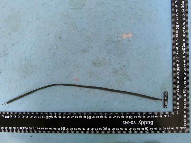
RAXAIOS65V
Nov 06, 2022HEOS 6.5 Platform Module
Equipment Class
DSS - Part 15 Spread Spectrum Transmitter