RAXWG7005BDraft 11n Wireless 4-port Broadband Router
Arcadyan Technology Corporation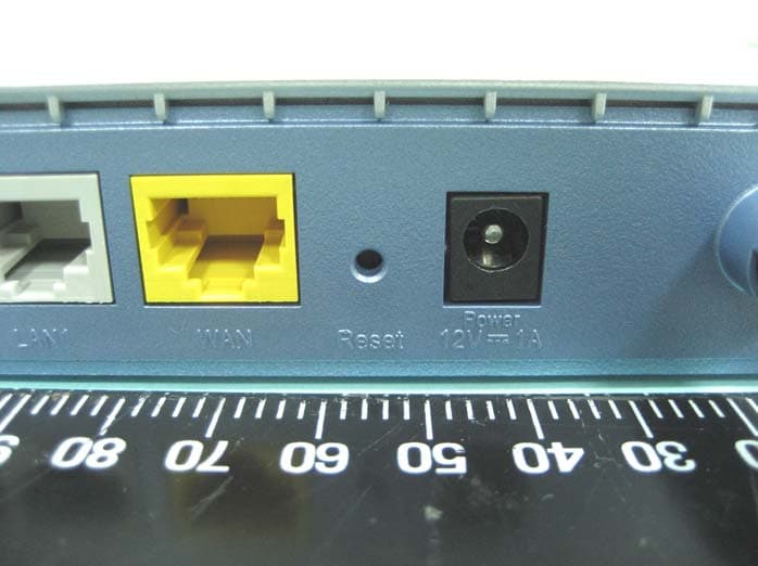
Click to zoom
Application Details
- Equipment Class
- DTS - Digital Transmission System
- Date of Grant
- Sep 18, 2007
- Application Purpose
- Original Equipment
- Date of Application
- Sep 18, 2007
- Equipment Note
- Draft 11n Wireless 4-port Broadband Router
- Frequency Range
- 2412.00000000 - 2462.00000000
- Country
- Taiwan
Documents & Files
Document Text
Text extracted from the exhibit documents filed with the FCC. Open a document above to read the original.
Users Manual
Barricade™ N Draft 11n Wireless 4-port Broadband Router SMCWBR14S-N 20 Mason Irvine, CA 92618 Phone: (949) 679-8000 Wireless Broadband Router User’s Guide From SMC’s line of award-winning connectivity solutions July 2007 R01 F/W 1.0 Information furnished is believed to be accurate and reliable. However, no responsibility is assumed by our company for its use, nor for any infringements of patents or other rights of third parties which may result from its use. No license is granted by implication or otherwise under any patent or patent rights of our company. We reserve the right to change specifications at any time without notice. Copyright © 2007 by SMC Networks, Inc. 20 Mason Irvine, CA 92618 All rights reserved. Trademar ks: Product and company names are trademarks or registered trademarks of their respective holders. i LIMITED WARRANTY Limited Warranty Statement: SMC Networks, Inc. (“SMC”) warrants its products to be free from defects in workmanship and materials, under normal use and service, for the applicable warranty term. All SMC products carry a standard 90-day limited warranty from the date of purchase from SMC or its Authorized Reseller. SMC may, at its own discretion, repair or replace any product not operating as warranted with a similar or functionally equivalent product, during the applicable warranty term. SMC will endeavor to repair or replace any product returned under warranty within 30 days of receipt of the product. The standard limited warranty can be upgraded to a Limited Lifetime* warranty by registering new products within 30 days of purchase from SMC or its Authorized Reseller. Registration can be accomplished via the enclosed product registration card or online via the SMC web site. Failure to register will not affect the standard limited warranty. The Limited Lifetime warranty covers a product during the Life of that Product, which is defined as the period of time during which the product is an “Active” SMC product. A product is considered to be “Active” while it is listed on the current SMC price list. As new technologies emerge, older technologies become obsolete and SMC will, at its discretion, replace an older product in its product line with one that incorporates these newer technologies. At that point, the obsolete product is discontinued and is no longer an “Active” SMC product. A list of discontinued products with their respective dates of discontinuance can be found at: http://www.smc.com/index.cfm?action=customer_service_warranty. All products that are replaced become the property of SMC. Replacement products may be either new or reconditioned. Any replaced or repaired product carries either a 30-day limited warranty or the remainder of the initial warranty, whichever is longer. SMC is not responsible for any custom software or firmware, configuration information, or memory data of Customer contained in, stored on, or integrated with any products returned to SMC pursuant to any warranty. Products returned to SMC should have any customer-installed accessory or add-on components, such as expansion modules, removed prior to returning the product for replacement. SMC is not responsible for these items if they are returned with the product. Customers must contact SMC for a Return Material Authorization number prior to returning any product to SMC. Proof of purchase may be required. Any product returned to SMC without a valid Return Material Authorization (RMA) number clearly marked on the outside of the package will be returned to customer at customer’s expense. For warranty claims within North America, please call our toll-free customer support number at (800) 762-4968. Customers are responsible for all shipping charges from their facility to SMC. SMC is responsible for return shipping charges from SMC to customer. LIMITED WARRANTY ii WARRANTIES EXCLUSIVE: IF AN SMC PRODUCT DOES NOT OPERATE AS WARRANTED ABOVE, CUSTOMER’S SOLE REMEDY SHALL BE REPAIR OR REPLACEMENT OF THE PRODUCT IN QUESTION, AT SMC’S OPTION. THE FOREGOING WARRANTIES AND REMEDIES ARE EXCLUSIVE AND ARE IN LIEU OF ALL OTHER WARRANTIES OR CONDITIONS, EXPRESS OR IMPLIED, EITHER IN FACT OR BY OPERATION OF LAW, STATUTORY OR OTHERWISE, INCLUDING WARRANTIES OR CONDITIONS OF MERCHANTABILITY AND FITNESS FOR A PARTICULAR PURPOSE. SMC NEITHER ASSUMES NOR AUTHORIZES ANY OTHER PERSON TO ASSUME FOR IT ANY OTHER LIABILITY IN CONNECTION WITH THE SALE, INSTALLATION, MAINTENANCE OR USE OF ITS PRODUCTS. SMC SHALL NOT BE LIABLE UNDER THIS WARRANTY IF ITS TESTING AND EXAMINATION DISCLOSE THE ALLEGED DEFECT IN THE PRODUCT DOES NOT EXIST OR WAS CAUSED BY CUSTOMER’S OR ANY THIRD PERSON’S MISUSE, NEGLECT, IMPROPER INSTALLATION OR TESTING, UNAUTHORIZED ATTEMPTS TO REPAIR, OR ANY OTHER CAUSE BEYOND THE RANGE OF THE INTENDED USE, OR BY ACCIDENT, FIRE, LIGHTNING, OR OTHER HAZARD. LIMITATION OF LIABILITY: IN NO EVENT, WHETHER BASED IN CONTRACT OR TORT (INCLUDING NEGLIGENCE), SHALL SMC BE LIABLE FOR INCIDENTAL, CONSEQUENTIAL, INDIRECT, SPECIAL, OR PUNITIVE DAMAGES OF ANY KIND, OR FOR LOSS OF REVENUE, LOSS OF BUSINESS, OR OTHER FINANCIAL LOSS ARISING OUT OF OR IN CONNECTION WITH THE SALE, INSTALLATION, MAINTENANCE, USE, PERFORMANCE, FAILURE, OR INTERRUPTION OF ITS PRODUCTS, EVEN IF SMC OR ITS AUTHORIZED RESELLER HAS BEEN ADVISED OF THE POSSIBILITY OF SUCH DAMAGES. SOME STATES DO NOT ALLOW THE EXCLUSION OF IMPLIED WARRANTIES OR THE LIMITATION OF INCIDENTAL OR CONSEQUENTIAL DAMAGES FOR CONSUMER PRODUCTS, SO THE ABOVE LIMITATIONS AND EXCLUSIONS MAY NOT APPLY TO YOU. THIS WARRANTY GIVES YOU SPECIFIC LEGAL RIGHTS, WHICH MAY VARY FROM STATE TO STATE. NOTHING IN THIS WARRANTY SHALL BE TAKEN TO AFFECT YOUR STATUTORY RIGHTS. * SMC will provide warranty service for one year following discontinuance from the active SMC price list. Under the limited lifetime warranty, internal and external power supplies, fans, and cables are covered by a standard one-year warranty from date of purchase. SMC Networks, Inc. 20 Mason Irvine, CA 92618 ii…
Text truncated - open the document above for the full version.
Users Manual
WIRELESS 4-27 Bandwidth • 20MHz: Sets the operation bandwidth as 20 MHz. • 20/40MHz: Allows automatic detection of the operation bandwidth between 20 MHz and 40 MHz. Choosing the bandwidth mode as 20/40MHz allows you to use the extension channel. Broadcast SSID Enable or disable the broadcasting of the SSID. Disabling SSID broadcast will provide increased security by hiding the SSID of your wireless network. Protected ModeEnabling this function to ensure the best performance of your 11n throughput in case there is a lot of interference from the 11g and 11b devices in the wireless network. 802.11e/WMM QoS Enable or disable the use of QoS. The QoS (Quality of Service) function allows you to differentiate WMM (Wi-Fi Multimedia) traffic and provide it with high-priority forwarding service ParameterDescription CONFIGURING THE BARRICADE 4-28 Access Control Using the Access Control functionality, you can restrict access based on MAC address. Each PC has a unique identifier known as a Medium Access Control (MAC) address. With MAC filtering enabled, the computers whose MAC address you have listed in the filtering table will be able to connect (or will be denied access) to the Barricade. WIRELESS 4-29 Security To make your wireless network safe, you should turn on the security function. The Barricade supports the following security mechanism: •WEP •WPA CONFIGURING THE BARRICADE 4-30 WEP If you want to use WEP to protect your wireless network, you need to set the same parameters for the Barricade and all your wireless clients. To generate the key automatically with passphrase, enter a string of characters and click the GENERATE button. Select the default key from the drop-down menu. Click SAVE SETTINGS. Note:The passphrase can consist of up to 32 alphanumeric characters. To manually configure the encryption key, enter five hexadecimal pairs of digits for the 64-bit key, or enter 13 pairs for the 128-bit key. (A hexadecimal digit is a number or letter in the range 0-9 or A-F.) Note:WEP protects data transmitted between wireless nodes, but does not protect any transmissions over your wired network or over the Internet. Parameter Description WEP ModeSelect 64 bit or 128 bit key to use for encryption. Key Entry Method Select Hex or ASCII to use for encryption key. Static WEP Key Setting You may automatically generate encryption keys or manually enter the keys. WIRELESS 4-31 WPA Wi-Fi Protected Access (WPA) combines temporal key integrity protocol (TKIP) and 802.1x mechanisms. It provides dynamic key encryption and 802.1x authentication service. Parameter Description AuthenticationChoose 802.1X or Pre-shared Key to use as the authentication method. • 802.1X: for the enterprise network with a RADIUS server. See “802.1X” on page 4-34. • Pre-shared key: for the SOHO network environment without an authentication server. Pre-shared key type Select the key type to be used in the Pre-shared Key. Pre-shared KeyType in the key here. CONFIGURING THE BARRICADE 4-32 WPA2 WPA2 is a product certification that is available through the Wi-Fi Alliance. WPA2 certifies that wireless equipment is compatible with the IEEE 802.11i standard. The WPA2 product certification formally replaces Wired Equivalent Privacy (WEP) and the other security features of the original IEEE 802.11 standard. The goal of WPA2 certification is to support the additional mandatory security features of the IEEE 802.11i standard that are not already included for products that support WPA. Parameter Description AuthenticationChoose 802.1X or Pre-shared Key to use as the authentication method. • 802.1X: for the enterprise network with a RADIUS server. See “802.1X” on page 4-34. • Pre-shared key: for the SOHO network environment without an authentication server. Pre-shared key type Select the key type to be used in the Pre-shared Key. Pre-shared KeyType in the key here. WIRELESS 4-33 WPA+WPA2 Wi-Fi Protected Access (WPA) combines temporal key integrity protocol (TKIP) and 802.1x mechanisms. It provides dynamic key encryption and 802.1x authentication service. Wi-Fi Protected Access 2 (WPA2) is a product certification that is available through the Wi-Fi Alliance. WPA2 certifies that wireless equipment is compatible with the IEEE 802.11i standard. The WPA2 product certification formally replaces Wired Equivalent Privacy (WEP) and the other security features of the original IEEE 802.11 standard. The goal of WPA2 certification is to support the additional mandatory security features of the IEEE 802.11i standard that are not already included for products that support WPA. CONFIGURING THE BARRICADE 4-34 802.1X If 802.1x is used in your network, then you should enable this function for the Barricade. Parameter Description AuthenticationChoose 802.1X or Pre-shared Key to use as the authentication method. • 802.1X: for the enterprise network with a RADIUS server. See “802.1X” on page 4-34. • Pre-shared key: for the SOHO network environment without an authentication server. Pre-shared key type Select the key type to be used in the Pre-shared Key. Pre-shared KeyType in the key here. WIRELESS 4-35 ParameterDescription AuthenticationEnable 802.1x authentication. Session Idle Timeout Defines a maximum period of time for which the connection is maintained during inactivity. Re-Authentication Period Defines a maximum period of time for which the authentication server will dynamically re-assign a session key to a connected client. Quiet PeriodDefines a maximum period of time for which the ADSL Router will wait between failed authentications. Server TypeThe Server Type of your authentication server is RADIUS. RADIUS Server Parameters Server IPThe IP address of your authentication server. Server PortThe port used for the authentication service. Secret KeyThe secret key shared between the authentication server and its clients. NAS-IDDefines the request identifier of the Network Access Server. CONFIGURING THE BARRICADE 4-36 Wi-Fi Protected Setup (WPS) The Barricade was imple…
Text truncated - open the document above for the full version.
Cover Letter(s)
Arcadyan Technology Corp. 4F, No.9, Park Avenue II, Science-based Industrial Park, Hsinchu 300, Taiwan FCC ID : RAXWG7005B Federal Communications Commission Authorization and Evaluation Division Confidentiality Request Pursuant to Sections 0.457 and 0.459 of the Commission’s Rules, the Applicant hereby requests confidential treatment of information accompanying this Application as outlined below: Schematics Block Diagram Operational Description The above materials contain trade secrets and proprietary information not customarily released to the public. The public disclosure of these matters might be harmful to the Applicant and provide unjustified benefits to its competitors. The Applicant understands that pursuant to Rule 0.457, disclosure of this Application and all accompanying documentation will not be made before the date of the Grant for this application. Sincerely yours, __________________________________ Simon Liu / Manager Email: [email protected] TEL: 886-3-578-7000 FAX: 886-3-563-7325
Cover Letter(s)
Arcadyan Technology Corp. 4F, No.9, Park Avenue II, Science-based Industrial Park, Hsinchu 300, Taiwan POWER OF ATTORNEY To whom it may concern: We, the undersigned Arcadyan Technology Corporation, hereby authorize Sporton International Inc. (Sporton) of Taiwan to act on our behalf in all matters relating to all processes required in the FCC Part 15C approval and any communication needed with the national authority. Any and all acts carried out by Sporton on our behalf shall have the same effects as acts of our own. If you have any questions regarding the authorization, please don’t hesitate to contact us. Sincerely yours, __________________________________ Simon Liu / Manager Email: [email protected] TEL: 886-3-505-1719 FAX: 886-3-563-7325
External Photos
SPORTON International Inc. PAGE NUMBER : A1 OF A7 TEL : 886-2-2696-2468 ISSUED DATE : FAX : 886-2-2696-2255 APPENDIX A. Photographs of EUT SPORTON International Inc. PAGE NUMBER : A2 OF A7 TEL : 886-2-2696-2468 ISSUED DATE : FAX : 886-2-2696-2255 SPORTON International Inc. PAGE NUMBER : A3 OF A7 TEL : 886-2-2696-2468 ISSUED DATE : FAX : 886-2-2696-2255 SPORTON International Inc. PAGE NUMBER : A4 OF A7 TEL : 886-2-2696-2468 ISSUED DATE : FAX : 886-2-2696-2255 SPORTON International Inc. PAGE NUMBER : A5 OF A7 TEL : 886-2-2696-2468 ISSUED DATE : FAX : 886-2-2696-2255 SPORTON International Inc. PAGE NUMBER : A6 OF A7 TEL : 886-2-2696-2468 ISSUED DATE : FAX : 886-2-2696-2255 SPORTON International Inc. PAGE NUMBER : A7 OF A7 TEL : 886-2-2696-2468 ISSUED DATE : FAX : 886-2-2696-2255
Internal Photos
SPORTON International Inc. PAGE NUMBER : A1 OF A8 TEL : 886-2-2696-2468 ISSUED DATE : FAX : 886-2-2696-2255 APPENDIX A. Photographs of EUT SPORTON International Inc. PAGE NUMBER : A2 OF A8 TEL : 886-2-2696-2468 ISSUED DATE : FAX : 886-2-2696-2255 SPORTON International Inc. PAGE NUMBER : A3 OF A8 TEL : 886-2-2696-2468 ISSUED DATE : FAX : 886-2-2696-2255 SPORTON International Inc. PAGE NUMBER : A4 OF A8 TEL : 886-2-2696-2468 ISSUED DATE : FAX : 886-2-2696-2255 SPORTON International Inc. PAGE NUMBER : A5 OF A8 TEL : 886-2-2696-2468 ISSUED DATE : FAX : 886-2-2696-2255 SPORTON International Inc. PAGE NUMBER : A6 OF A8 TEL : 886-2-2696-2468 ISSUED DATE : FAX : 886-2-2696-2255 SPORTON International Inc. PAGE NUMBER : A7 OF A8 TEL : 886-2-2696-2468 ISSUED DATE : FAX : 886-2-2696-2255 SPORTON International Inc. PAGE NUMBER : A8 OF A8 TEL : 886-2-2696-2468 ISSUED DATE : FAX : 886-2-2696-2255
RF Exposure Info
Report No.: FR741903-03AB FCC ID: RAXWG7005B Page No. : 1 of 3 Appendix C. Maximum Permissible Exposure Report No.: FR741903-03AB FCC ID: RAXWG7005B Page No. : 2 of 3 1. Maximum Permissible Exposure 1.1. Applicable Standard Systems operating under the provisions of this section shall be operated in a manner that ensures that the public is not exposed to radio frequency energy levels in excess limit for maximum permissible exposure. In accordance with 47 CFR FCC Part 2 Subpart J, section 2.1091 this device has been defined as a mobile device whereby a distance of 0.2 m normally can be maintained between the user and the device. (A) Limits for Occupational / Controlled Exposure Frequency Range (MHz) Electric Field Strength (E) (V/m) Magnetic Field Strength (H) (A/m) Power Density (S) (mW/ cm²) Averaging Time |E|²,|H|² or S (minutes) 0.3-3.0 614 1.63 (100)* 6 3.0-30 1842 / f 4.89 / f (900 / f)* 6 30-300 61.4 0.163 1.0 6 300-1500 F/300 6 1500-100,000 5 6 (B) Limits for General Population / Uncontrolled Exposure Frequency Range (MHz) Electric Field Strength (E) (V/m) Magnetic Field Strength (H) (A/m) Power Density (S) (mW/ cm²) Averaging Time |E|²,|H|² or S (minutes) 0.3-1.34 614 1.63 (100)* 30 1.34-30 824/f 2.19/f (180/f)* 30 30-300 27.5 0.073 0.2 30 300-1500 F/1500 30 1500-100,000 1.0 30 Note: f = frequency in MHz ; *Plane-wave equivalent power density 1.2. MPE Calculation Method E (V/m) = d GP××30 Power Density: Pd (W/m²) = 377 2 E E = Electric field (V/m) P = Peak RF output power (W) G = EUT Antenna numeric gain (numeric) d = Separation distance between radiator and human body (m) The formula can be changed to Pd = 2 377 30 d GP × ×× From the peak EUT RF output power, the minimum mobile separation distance, d=0.2m, as well as the gain of the used antenna, the RF power density can be obtained. Report No.: FR741903-03AB FCC ID: RAXWG7005B Page No. : 3 of 3 1.3. Calculated Result and Limit Antenna Type : Dipole Antenna Max Conducted Power for IEEE 802.11b/g : 18.11dBm Antenna Gain (dBi) Antenna Gain (numeric) Peak Output Power (dBm) Peak Output Power ( mW ) Power Density (S) (mW/cm²) Limit of Power Density (S) (mW/cm²) Test Result 2 1.5849 18.1100 64.7143 0.020415 1 Complies
RF Exposure Info
Report No.: FR741903-03AA FCC ID: RAXWG7005B Page No. : 1 of 3 Appendix C. Maximum Permissible Exposure Report No.: FR741903-03AA FCC ID: RAXWG7005B Page No. : 2 of 3 1. Maximum Permissible Exposure 1.1. Applicable Standard Systems operating under the provisions of this section shall be operated in a manner that ensures that the public is not exposed to radio frequency energy levels in excess limit for maximum permissible exposure. In accordance with 47 CFR FCC Part 2 Subpart J, section 2.1091 this device has been defined as a mobile device whereby a distance of 0.2 m normally can be maintained between the user and the device. (A) Limits for Occupational / Controlled Exposure Frequency Range (MHz) Electric Field Strength (E) (V/m) Magnetic Field Strength (H) (A/m) Power Density (S) (mW/ cm²) Averaging Time |E|²,|H|² or S (minutes) 0.3-3.0 614 1.63 (100)* 6 3.0-30 1842 / f 4.89 / f (900 / f)* 6 30-300 61.4 0.163 1.0 6 300-1500 F/300 6 1500-100,000 5 6 (B) Limits for General Population / Uncontrolled Exposure Frequency Range (MHz) Electric Field Strength (E) (V/m) Magnetic Field Strength (H) (A/m) Power Density (S) (mW/ cm²) Averaging Time |E|²,|H|² or S (minutes) 0.3-1.34 614 1.63 (100)* 30 1.34-30 824/f 2.19/f (180/f)* 30 30-300 27.5 0.073 0.2 30 300-1500 F/1500 30 1500-100,000 1.0 30 Note: f = frequency in MHz ; *Plane-wave equivalent power density 1.2. MPE Calculation Method E (V/m) = d GP××30 Power Density: Pd (W/m²) = 377 2 E E = Electric field (V/m) P = Peak RF output power (W) G = EUT Antenna numeric gain (numeric) d = Separation distance between radiator and human body (m) The formula can be changed to Pd = 2 377 30 d GP × ×× From the peak EUT RF output power, the minimum mobile separation distance, d=0.2m, as well as the gain of the used antenna, the RF power density can be obtained. Report No.: FR741903-03AA FCC ID: RAXWG7005B Page No. : 3 of 3 1.3. Calculated Result and Limit Antenna Type : Dipole Antenna Max Conducted Power for 802.11n 20MHz Ant. A : 16.71dBm Antenna Gain (dBi) Antenna Gain (numeric) Peak Output Power (dBm) Peak Output Power ( mW ) Power Density (S) (mW/cm²) Limit of Power Density (S) (mW/cm²) Test Result 2 1.5849 16.7100 46.8813 0.014789 1 Complies Antenna Type : Dipole Antenna Max Conducted Power for IEEE 802.11n 20MHz Ant. B: 16.26dBm Antenna Gain (dBi) Antenna Gain (numeric) Peak Output Power (dBm) Peak Output Power ( mW ) Power Density (S) (mW/cm²) Limit of Power Density (S) (mW/cm²) Test Result 2 1.5849 16.2600 42.2669 0.013334 1 Complies Antenna Type : Dipole Antenna Max Conducted Power for IEEE 802.11n 20MHz Ant. A + Ant. B: 19.50dBm Antenna Gain (dBi) Antenna Gain (numeric) Peak Output Power (dBm) Peak Output Power ( mW ) Power Density (S) (mW/cm²) Limit of Power Density (S) (mW/cm²) Test Result 2 1.5849 19.5000 89.1251 0.028116 1 Complies Antenna Type : Dipole Antenna Max Conducted Power for IEEE 802.11n 40MHz Ant. A: 16.09dBm Antenna Gain (dBi) Antenna Gain (numeric) Peak Output Power (dBm) Peak Output Power ( mW ) Power Density (S) (mW/cm²) Limit of Power Density (S) (mW/cm²) Test Result 2 1.5849 16.0900 40.6443 0.012822 1 Complies Antenna Type : Dipole Antenna Max Conducted Power for IEEE 802.11n 40MHz Ant. B: 16.66dBm Antenna Gain (dBi) Antenna Gain (numeric) Peak Output Power (dBm) Peak Output Power ( mW ) Power Density (S) (mW/cm²) Limit of Power Density (S) (mW/cm²) Test Result 2 1.5849 16.6600 46.3447 0.014620 1 Complies Antenna Type : Dipole Antenna Max Conducted Power for IEEE 802.11n 40MHz Ant. A + Ant. B: 19.20dBm Antenna Gain (dBi) Antenna Gain (numeric) Peak Output Power (dBm) Peak Output Power ( mW ) Power Density (S) (mW/cm²) Limit of Power Density (S) (mW/cm²) Test Result 2 1.5849 19.2000 83.1764 0.026239 1 Complies
Test Report
SPORTON International Inc. No. 52, Hwa Ya 1st Rd., Kwei-Shan Hsiang, TaoYuan Hsien, Taiwan, R.O.C. Ph: 886-3-327-3456 / FAX: 886-3-327-0973 / www.sporton.com.tw Report Format Version: 01 FCC RADIO TEST REPORT Applicant’s company Arcadyan Technology Corporation Applicant Address 4F, No.9, Park Avenue II, Science-based Industrial Park, Hsinchu 300, Taiwan, R.O.C. FCC ID RAXWG7005B Manufacturer’s company Arcadyan Technology Corporation Manufacturer Address 4F, No.9, Park Avenue II, Science-based Industrial Park, Hsinchu 300, Taiwan, R.O.C. Product Name Draft 11n Wireless 4-port Broadband Router Brand Name SMC Model Name SMCWBR14S-N Test Rule 47 CFR FCC Part 15 Subpart C § 15.247 Test Freq. Range 2400 ~ 2483.5MHz Received Date Apr. 4, 2007 Final Test Date May 9, 2007 Submission Type Original Equipment Statement Test result included is only for the 802.11b/g part of the product. The test result in this report refers exclusively to the presented test model / sample. Without written approval of SPORTON International Inc., the test report shall not be reproduced except in full. The measurements and test results shown in this test report were made in accordance with the procedures and found in compliance with the limit given in ANSI C63.4-2003 and 47 CFR FCC Part 15 Subpart C. The test equipment used to perform the test is calibrated and traceable to NML/ROC. Report No.: FR741903-03AB Report Format Version: 01 Page No. : i of ii FCC ID: RAXWG7005B Issued Date : Sep. 14, 2007 Table of Contents 1. CERTIFICATE OF COMPLIANCE ......................................................................................................................... 1 2. SUMMARY OF THE TEST RESULT .......................................................................................................................... 2 3. GENERAL INFORMATION .................................................................................................................................. 3 3.1. Product Details....................................................................................................................................................................................3 3.2. Accessories .........................................................................................................................................................................................3 3.3. Table for Filed Antenna.......................................................................................................................................................................4 3.4. Table for Carrier Frequencies .............................................................................................................................................................4 3.5. Table for Test Modes ...........................................................................................................................................................................5 3.6. Table for Testing Locations..................................................................................................................................................................5 3.7. Table for Supporting Units ...................................................................................................................................................................5 3.8. Table for Parameters of Test Software Setting .....................................................................................................................................6 3.9. Test Configurations .............................................................................................................................................................................7 4. TEST RESULT ................................................................................................................................................... 10 4.1. AC Power Line Conducted Emissions Measurement.........................................................................................................................10 4.2. Maximum Peak Output Power Measurement ...................................................................................................................................19 4.3. Power Spectral Density Measurement ..............................................................................................................................................21 4.4. 6dB Spectrum Bandwidth Measurement ..........................................................................................................................................26 4.5. Radiated Emissions Measurement ....................................................................................................................................................31 4.6. Band Edge Emissions Measurement .................................................................................................................................................49 4.7. Antenna Requirements .....................................................................................................................................................................56 5. LIST OF MEASURING EQUIPMENTS ................................................................................................................... 57 6. TEST LOCATION.............................................................................................................................................. 59 7. TAF CERTIFICATE OF ACCREDITATION ............................................................................................................. 60 APPENDIX A. PHOTOGRAPHS OF EUT.........................................................................................................A1 ~ A15 APPENDIX B. TEST PHOTOS.......................................................................................................................... B1 ~ B5 APPENDIX C. MAXIMUM PERMISSIBLE EXPOSURE...…
Text truncated - open the document above for the full version.
Test Report
SPORTON International Inc. No. 52, Hwa Ya 1st Rd., Kwei-Shan Hsiang, TaoYuan Hsien, Taiwan, R.O.C. Ph: 886-3-327-3456 / FAX: 886-3-327-0973 / www.sporton.com.tw Report Format Version: 01 FCC RADIO TEST REPORT Applicant’s company Arcadyan Technology Corporation Applicant Address 4F, No.9, Park Avenue II, Science-based Industrial Park, Hsinchu 300, Taiwan, R.O.C. FCC ID RAXWG7005B Manufacturer’s company Arcadyan Technology Corporation Manufacturer Address 4F, No.9, Park Avenue II, Science-based Industrial Park, Hsinchu 300, Taiwan, R.O.C. Product Name Draft 11n Wireless 4-port Broadband Router Brand Name SMC Model Name SMCWBR14S-N Test Rule 47 CFR FCC Part 15 Subpart C § 15.247 Test Freq. Range 2400 ~ 2483.5MHz Received Date Apr. 4, 2007 Final Test Date May 9, 2007 Submission Type Original Equipment Statement Test result included is only for the 802.11n part of the product. The test result in this report refers exclusively to the presented test model / sample. Without written approval of SPORTON International Inc., the test report shall not be reproduced except in full. The measurements and test results shown in this test report were made in accordance with the procedures and found in compliance with the limit given in ANSI C63.4-2003 and 47 CFR FCC Part 15 Subpart C. The test equipment used to perform the test is calibrated and traceable to NML/ROC. Report No.: FR741903-03AA Report Format Version: 01 Page No. : i of ii FCC ID: RAXWG7005B Issued Date : Sep. 14, 2007 Table of Contents 1. CERTIFICATE OF COMPLIANCE ......................................................................................................................... 1 2. SUMMARY OF THE TEST RESULT .......................................................................................................................... 2 3. GENERAL INFORMATION .................................................................................................................................. 3 3.1. Product Details....................................................................................................................................................................................3 3.2. Accessories .........................................................................................................................................................................................5 3.3. Table for Filed Antenna.......................................................................................................................................................................5 3.4. Table for Carrier Freque…
Text truncated - open the document above for the full version.
Contact Information
Applicant
Simon Liu(Manager)
Technical Contact
Sporton International Inc.Wayne Hsu
No. 52, Hwa Ya 1st Rd., Hwa Ya Technology Park · Tao Yuan · Taiwan
Test Firm
Sporton International Inc.Alex Chen
Technical Specifications
| # | Rule Parts | Frequency Range | Power Output |
|---|---|---|---|
| 1 | 15C | 2.41 GHz - 2.46 GHz | 89.10 mW |
Other Applications from Arcadyan Technology Corporation
RAXWE6204430
Jan 27, 2024Wi-Fi Extender
Equipment Class
DTS - Digital Transmission System
RAXAIOS7
Nov 08, 2023HEOS 7.0 Platform Module
Equipment Class
NII - Unlicensed National Information Infrastructure TX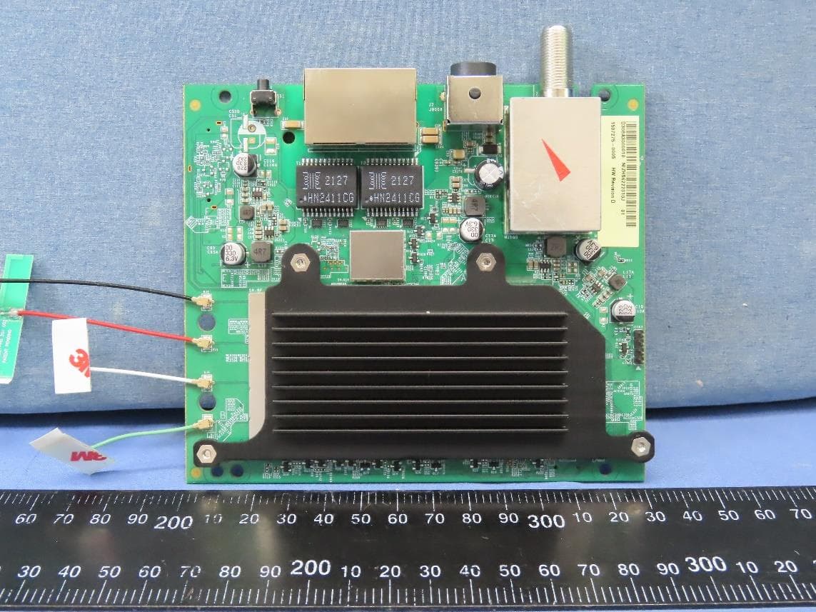
RAXWR3210
Jul 13, 2023Standalone Router
Equipment Class
DTS - Digital Transmission System
RAXWE7224443
Jan 11, 2023Verizon Wi-Fi Extender
Equipment Class
6PP - 15E 6 GHz Subordinate Indoor Device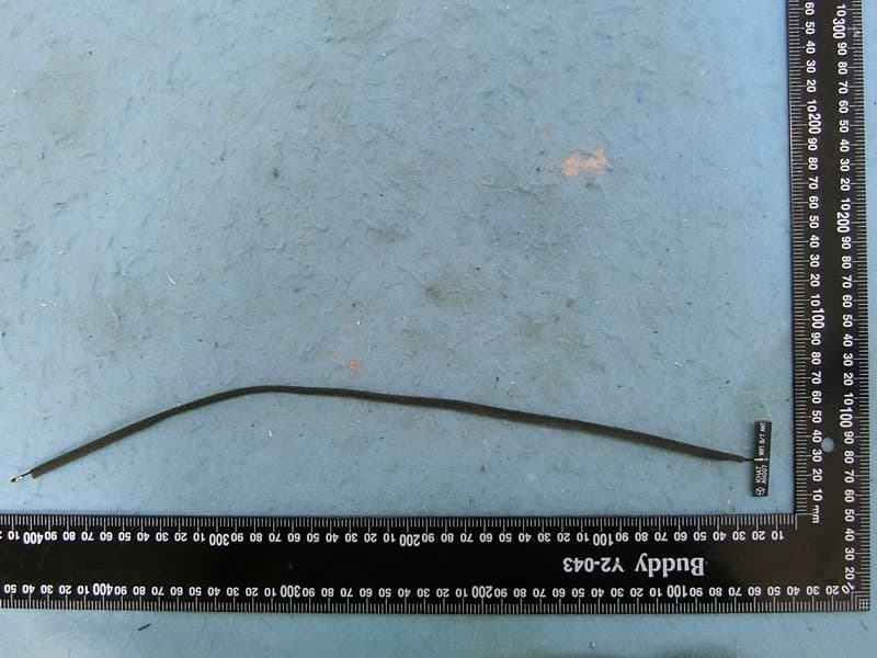
RAXAIOS65V
Nov 06, 2022HEOS 6.5 Platform Module
Equipment Class
DSS - Part 15 Spread Spectrum Transmitter