RAXWN4501D-U5U.S. Robotics 802.11g 54Mbps USB Adapter
Arcadyan Technology Corporation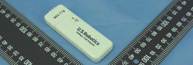
Click to zoom
Application Details
- Equipment Class
- DTS - Digital Transmission System
- Date of Grant
- Sep 22, 2004
- Application Purpose
- Original Equipment
- Date of Application
- Sep 22, 2004
- Equipment Note
- U.S. Robotics 802.11g 54Mbps USB Adapter
- Frequency Range
- 2412.00000000 - 2462.00000000
- Country
- Taiwan
Documents & Files
Document Text
Text extracted from the exhibit documents filed with the FCC. Open a document above to read the original.
Users Manual
Contents: About the 802.11g 54Mbps USB Adapter > Network Configuration and Planning Adapter Installation and Configuration for Windows 98SE/2000/Me/ XP Navigating the Wireless Configuration Utility Troubleshooting Glossary Product Specifications for 802.11g 54Mbps USB Adapter U.S. Robotics Corporation Limited Warranty Regulatory Information 802.11g 54Mbps USB Adapter User Guide About the 802.11g 54Mbps USB Adapter The 802.11g 54Mbps USB Adapter is compatible with a USB port of any standard Windows laptop or desktop computer. As the 802.11g 54Mbps USB Adapter is a Plug and Play device, Windows 98SE, 2000, Me, and XP will automatically recognise it in the installation process. Upon successful installation, the 802.11g 54Mbps USB Adapter will be able to communicate with other home and office wireless networking products. LED Information (WLAN TX/RX) LED: The WLAN TX/RX LED is lighted green when the 802.11g 54Mbps USB Adapter driver is correctly installed and blinks green when traffic is being processed. If the driver is not correctly installed, this LED will be off. rev 1.0 9-04 R46.0764.00 Contents: About the 802.11g 54Mbps USB Adapter Network Configuration and Planning > Adapter Installation and Configuration for Windows 98SE/2000/Me/ XP Navigating the Wireless Configuration Utility Troubleshooting Glossary Product Specifications for 802.11g 54Mbps USB Adapter U.S. Robotics Corporation Limited Warranty Regulatory Information 802.11g 54Mbps USB Adapter User Guide Network Configuration and Planning The 802.11g 54Mbps USB Adapter supports legacy Ethernet LAN network configuration options as defined by the IEEE 802 standards committee. The 802.11g 54Mbps USB Adapter can be configured in one of the following modes: Infrastructure - Used for home networks, business networks, and public hotspots when connecting to a wireless router or access point Ad Hoc - Used for peer-to-peer network connections when connecting directly to another wireless adapter NETWORK TOPOLOGY An Infrastructure configuration extends the accessibility of a PC to a wired LAN and doubles the effective wireless transmission range for two 802.11g 54Mbps USB Adapters. Since the Wireless Router or Access Point is able to forward data within its BSS, the effective transmission range in an infrastructure LAN is doubled. The use of a unique SSID is essential. All 802.11g 54Mbps USB Adapters that are in the wireless network must be configured with the same SSID that is used by the access point or wireless router. The Infrastructure Wireless LAN configuration is appropriate for enterprise-scale wireless access to a central database or other central applications for mobile users. An 802.11g Ad Hoc wireless LAN is a group of computers, each equipped with one 802.11g 54Mbps USB Adapter, that are connected as an independent wireless LAN. The wireless devices in a specific 802.11g Ad Hoc wireless LAN must be configured to share the same radio channel. 802.11g Ad Hoc wireless LAN configurations are appropriate for small departments or SOHO environments. The 802.11g 54Mbps USB Adapter provides access to a wired LAN for workstations. An integrated wireless and wired LAN is called an Infrastructure configuration. A group of 802.11g 54Mbps USB Adapter users and a Wireless Router or Access Point compose a Basic Service Set (BSS). Each 802.11g 54Mbps USB Adapter in a BSS can talk to any computer in the wired LAN infrastructure through the Wireless Router or Access Point. Contents: About the 802.11g 54Mbps USB Adapter Network Configuration and Planning Adapter Installation and Configuration for Windows 98SE/2000/Me/ XP Navigating the Wireless Configuration Utility Troubleshooting Glossary Product Specifications for 802.11g 54Mbps USB Adapter U.S. Robotics Corporation Limited Warranty Regulatory Information 802.11g 54Mbps USB Adapter User Guide Adapter Installation and Configuration for Windows 98SE/2000/Me/XP System Requirements In order to install and use the 802.11g 54Mbps USB Adapter, your computer must meet the following requirements: An available USB port 10 Mb free disk space for utility and driver installation Windows 98SE, 2000, Me, or XP 802.11g 54Mbps USB Adapter Installation Prepare for installation ATTENTION: You must install your software and drivers before you physically connect the 802.11g 54Mbps USB Adapter. Note: Your model number is 5422. Note: For the most updated information, visit: http://www.usr.com/support Turn on your desktop or laptop computer. Type your password if you are prompted to do so. Note: Be sure to find out what letter your CD-ROM drive uses before you begin installing your new product. You will need to know this to properly install your software. Note: During the Installation procedure, you may be prompted for your Windows Operating system CD-ROM. Make sure you have it available in case you need it. Note: If the 802.11g 54Mbps USB Adapter does not fit into an available USB port on your computer because of other USB devices that are connected, use an USB extension cable or a USB hub to connect the 802.11g 54Mbps USB Adapter. Note: If you are connecting the 802.11g 54Mbps USB Adapter to a 1.1 USB port, you may see a message informing you that a Hi-Speed USB device is being connected to a USB port that is not Hi-Speed. This will not affect the installation procedure. Step One: Install your software and drivers Insert your U.S. Robotics Installation CD-ROM into your CD-ROM drive. Note: If your CD-ROM does not automatically launch, click Windows Start, Run, and type D:\setup (if your CD-ROM drive uses a different letter, type that letter in place of "D") and click OK. The Installation CD Graphic User Interface (GUI) will appear on your screen. If prompted, select your preferred language. Read the license agreement and click Yes. Select the 802.11g 54Mbps USB Adapter and click Software. Click Wireless USB Adapter Utility and Drivers. Follow the on-screen instructions to finish the installation procedure. Windows Me: …
Text truncated - open the document above for the full version.
External Photos
Page 1 CONSTRUCTION PHOTOS OF EUT
ID Label/Location Info
(Fig. 1) FCC ID: RAXWN4501D-U5 LABEL LOCATION Label
Internal Photos
Page 1 CONSTRUCTION PHOTOS OF EUT Page 2 Page 3 Page 4 Page 5 Page 6 Page 7
Operational Description
FCC ID: RAXWN4501D-U5 Report No. 930908H01 Operational Description This device is a U.S. Robotics 802.11g 54Mbps USB Adapter, the maximum data rate could be up to 54Mbps which OFDM technique will be applied. If the signal to noise radio is too poor which could not support 54Mbps, the 11Mbps data rate with CCK technique will be applied. The transmitter of the EUT (U.S. Robotics 802.11g 54Mbps USB Adapter) is powered by host equipment. The antenna type used in this product is PCB antenna without connector . The other instruction, please have a look at the users manual.
RF Exposure Info
FCC ID: RAXWN4501D-U5 Report No.: SA 930908H011Issued: Sep. 21, 2004 SAR TEST REPORT REPORT NO.: SA930908H01 MODEL NO.: USR5422 SERIESMODEL NO.: USRXX5422 (The “X” could be "0~9", "A~Z", or "None", and "XX" is defined for selling in different country or area.) RECEIVED: Aug. 09, 2004 TESTED: Aug. 09, 2004 APPLICANT: U.S. Robotics ADDRESS: 935 National Parkway, Schaumburg, IL 60173, U.S.A. ISSUED BY: Advance Data Technology Corporation LAB ADDRESS:No. 47, 14th Ling, Chia PauTsuen,Lin Kou Hsiang 244, Taipei Hsien, Taiwan, R.O.C. TESTLOCATION: No. 19, Hwa Ya 2 nd Rd., Wen HwaTsuen,Kwei ShanHsiang,Taoyuan Hsien 333, Taiwan, R.O.C. This test report consists of 37 pages in total except Appendix. It may be duplicated completely for legal use with the approval of the applicant. It should not be reproduced except in full, without the written approval of our laboratory. The client should not use it to claim product endorsement by CNLA, A2LA or any government agencies. The test results in the report only apply to the tested sample. 0528 ILAC MRA No. 2177-01 FCC ID: RAXWN4501D-U5 Report No.: SA 930908H012Issued: Sep. 21, 2004 Table of Contents 1.CERTIFICATION............................................................................................................3 2.GENERAL INFORMATION............................................................................................3 2.1 GENERAL DESCRIPTION OF EUT..............................................................................4 2.2 GENERAL DESCRIPTION OF APPLIED STANDARDS..............................................5 2.3 GENERAL INOFRMAT ION OF THE SAR SYSTEM.....................................................5 2.4 GENERAL DESCRIPTION OF THE SPATIAL PEAK SAR EVALUATION ..................9 3.DESCRIPTION OF TEST MODES AND CONFIGURATIONS...................................13 4.DESCRIPTION OF SUPPORT UNITS........................................................................16 5.TEST RESULTS...........................................................................................................17 5.1 TEST PROCEDURES .................................................................................................17 5.2 MEASURED SAR RESULT .........................................................................................18 5.3 SAR LIMITS.................................................................................................................20 5.4 RECIPES FOR TISSUE SIMULATING LIQUIDS........................................................24 5.5 TEST EQUIPMENT FOR TISSUE PROPERTY.........................................................26 6.SYSTEM VALIDATION.................................................................................................27 6.1 TEST EQUIPMENT......................................................................................................27 6.2 TEST PROCEDURE....................................................................................................27 6.3 VALIDATION RESULT.................................................................................................29 6.4 SYSTEM VALIDATION UNCERTAINTIES..................................................................30 7.MEASUREMENT SAR PROCEDURE UNCERTAINTIES..........................................31 7.1 PROBE CALIBRATION UNCERTAINTY.....................................................................31 7.2 ISOTROPY UNCERTAINTY........................................................................................31 7.3 BOUNDARY EFFECT UNCERTAINTY.......................................................................32 7.4 PROBE LINEARITY UNCERTAINTY..........................................................................32 7.5 READOUT ELECTRONICS UNCERTAINTY..............................................................32 7.6 RESPONSE TIME UNCERTAINTY.............................................................................33 7.7 INTEGRATION TIME UNCERTAINTY.........................................................................34 7.8 PROBE POSITIONER MECHANICAL TOLERANCE.................................................34 7.9 PROBE POSITIONING................................................................................................35 7.10PHANTOM UNCERTAINTY.........................................................................................35 7.11DASY4 UNCERTAINTY BUDGET...............................................................................36 8.INFORMATION ON THE TESTING LABORATORIES...............................................37 APPENDIX A: TEST CONFIGURATIONS AND TEST DATA APPENDIX B: ADT SAR MEASUREMENT SYSTEM APPENDIX C: PHOTOGRAPHS OF SYSTEM VALIDATION APPENDIX D: SYSTEM CERTIFICATE & CALIBRATION FCC ID: RAXWN4501D-U5 Report No.: SA 930908H013Issued: Sep. 21, 2004 1. CERTIFICATION PRODUCT : U.S. Robotics 802.11g 54Mbps USB Adapter MODEL NO. : USR5422 SERIESMODEL NO.: USRXX5422 (The “X” could be "0~9", "A~Z", or "None", and "XX" is defined for selling in different country or area.) BRAND NAME : U.S. Robotics APPLICANT : U.S. Robotics TESTED : Aug. 09, 2004 TEST SAMPLE : MASS-PRODUCTION STANDARDS : FCC Part 2(Section 2.1093), FCC OET Bulletin 65, Supplement C (01-01), RSS-102 The above equipment (Model: USR5422) has been tested byAdvance Data Technology Corporation, and found compliance with the requirement of the above standards. The test record, data evaluation & Equipment Under Test (EUT) configurations represented herein are true and accurate accounts of the measurements of the sample’ s EMC characteristics under the conditions specified in this report. PREPARED BY:, DATE:Sep. 21, 2004 ( Windy Chou ) TECHNICAL ACCEPTANCE:, DATE:Sep. 21, 2004 Responsible for RF ( Ansen Lei ) APPROVED BY:, DATE:Sep. 21, 2004 ( Cody Chang, Deputy Manager ) FCC ID: RAXWN4501D-U5 Report No.: SA 930908H014Issued: Sep. 21, 2004 2. GENERAL INFORMATION 2.1 GENERAL DESCRIPTION OF EUT PRODUCT U.S. Robotics 802.11g 54Mbps USB …
Text truncated - open the document above for the full version.
Test Report
Report No. 930908H01 1 The Measurement of Conducted Spurious Emissions CONDUCTED SPURIOUS EMISSIONS MEASUREMENT 1. LIMITS OF CONDUCTED SPURIOUS EMISSIONS EASUREMENT Below 20dB of the highest emission level of operating band (in 100KHz Resolution Bandwidth, see Section 15.247(c)). Emissions which fall in the restricted bands, as defined in Section 15.205(a), must also comply with the limits specified in Section 15.209(a) (see Section 15.205(c)). 2. TEST INSTRUMENTS Description & ManufacturerModel No.Serial No.Calibrated Until R&S SPECTRUM ANALYZERFSP40100036Nov. 27, 2005 High pass filter 2.4G WHK3.1/18G- 10SS SN4Jun. 08, 2005 NOTE: 1.The calibration interval of the above test instruments is 12 months and the calibrations are traceable to NML/ROC and NIST/USA. 3. TEST PROCEDURE The transmitter output was connected to the spectrum analyzer via a low lose cable. Set both RBW and VBW of spectrum analyzer to 100 kHz with suitable frequency span including 100 kHz bandwidth from band edge. The band edges was measured and recorded. Report No. 930908H01 2 4. TEST SETUP 5. EUT OPERATING CONDITIONS The software provided by client to enable the EUT under transmission condition continuously at lowest, middle and highest channel frequencies individually. EUT SPECTRUM ANALYZER Report No. 930908H01 3 TEST RESULTS – For 802.11b The spectrum plots are attached on the following 2 pages. It shows compliance with the requirement in part 15.247(C),.15.205 and 15.209. Report No. 930908H01 4 Ch1 Report No. 930908H01 5 Ch11 Report No. 930908H01 6 TEST RESULTS – For 802.11g The spectrum plots are attached on the following 2 pages. It shows compliance with the requirement in part 15.247(C),.15.205 and 15.209. Report No. 930908H01 7 Ch1 Report No. 930908H01 8 Ch11
Test Report
FCC ID: RAXWN4501D-U5 Report No.: RF930908H011 Issued: Sep. 20, 2004 FCC TEST REPORT REPORT NO.:RF930908H01 MODEL NO.:USRXX5422 RECEIVED:Sep. 08, 2004 TESTED:Sep. 11 to 14, 2004 APPLICANT: Arcadyan Technology Corporation ADDRESS: 4F, No. 9, Park Avenue II, Science-based Industrial Park, Hsinchu 300, Taiwan, R.O.C. ISSUED BY:Advance Data Technology Corporation LAB LOCATION:No. 81-1, Lu Liao Keng, 9 Ling, Wu Lung Tsuen, Chiung Lin Hsiang, Hsin Chu Hsien, Taiwan, R.O.C. This test report consists of 59 pages in total. It may be duplicated completely for legal use with the approval of the applicant. It should not be reproduced except in full, without the written approval of our laboratory. The client should not use it to claim product endorsement by CNLA, A2LA or any government agencies. The test results in the report only apply to the tested sample. The test results in this report are traceable to the national or international standards. 0536 No. 2177-01 ILAC MRA FCC ID: RAXWN4501D-U5 Report No.: RF930908H012 Issued: Sep. 20, 2004 Table of Contents 1CERTIFICATION ........................................................................................... 4 2SUMMARY OF TEST RESULTS................................................................... 5 3GENERAL INFORMATION ........................................................................... 6 3.1GENERAL DESCRIPTION OF EUT.............................................................. 6 3.2DESCRIPTION OF TEST MODES................................................................ 7 3.3GENERAL DESCRIPTION OF APPLIED STANDARDS ............................... 7 3.4DESCRIPTION OF SUPPORT UNITS.......................................................... 8 3.5CONFIGURATION OF SYSTEM UNDER TEST ........................................... 8 4TEST TYPES AND RESULTS....................................................................... 9 4.1CONDUCTED EMISSION MEASUREMENT ................................................ 9 4.1.1LIMITS OF CONDUCTED EMISSION MEASUREMENT ............................. 9 4.1.2TEST INSTRUMENTS .................................................................................. 9 4.1.3TEST SETUP .............................................................................................. 10 4.1.4EUT OPERATING CONDITIONS.................................................................11 4.1.5TEST RESULTS.......................................................................................... 12 4.2RADIATED EMISSION MEASUREMENT ................................................... 14 4.2.1LIMITS OF RADIATED EMISSION MEASUREMENT ................................ 14 4.2.2TEST INSTRUMENTS ................................................................................ 15 4.2.3TEST PROCEDURES................................................................................. 16 4.2.4TEST SETUP .............................................................................................. 17 4.2.5EUT OPERATING CONDITIONS................................................................ 17 4.2.6TEST RESULTS ......................................................................................... 18 4.2.7TEST RESULTS - DSSS............................................................................. 19 4.2.8TEST RESULTS -OFDM ............................................................................. 22 4.36DB BANDWIDTH MEASUREMENT.......................................................... 25 4.3.1LIMITS OF 6DB BANDWIDTH MEASUREMENT ....................................... 25 4.3.2TEST INSTRUMENTS ................................................................................ 25 4.3.3TEST PROCEDURE ................................................................................... 26 4.3.4TEST SETUP .............................................................................................. 26 4.3.5EUT OPERATING CONDITIONS................................................................ 26 4.3.6TEST RESULTS-DSSS............................................................................... 27 4.3.7TEST RESULTS-OFDM .............................................................................. 31 4.4MAXIMUM PEAK OUTPUT POWER .......................................................... 35 4.4.1LIMITS OF MAXIMUM PEAK OUTPUT POWER MEASUREMENT ........... 35 4.4.2TEST INSTRUMENTS ................................................................................ 35 FCC ID: RAXWN4501D-U5 Report No.: RF930908H013 Issued: Sep. 20, 2004 4.4.3TEST PROCEDURES................................................................................. 36 4.4.4TEST SETUP .............................................................................................. 36 4.4.5EUT OPERATING CONDITIONS................................................................ 36 4.4.6TEST RESULTS- DSSS.............................................................................. 37 4.4.7TEST RESULTS- OFDM ............................................................................. 38 4.5POWER SPECTRAL DENSITY MEASUREMENT...................................... 39 4.5.1LIMITS OF POWER SPECTRAL DENSITY MEASUREMENT ................... 39 4.5.2TEST INSTRUMENTS ................................................................................ 39 4.5.3TEST PROCEDURE ................................................................................... 40 4.5.4TEST SETUP .............................................................................................. 40 4.5.5EUT OPERATING CONDITIONS................................................................ 40 4.5.6TEST RESULTS-DSSS............................................................................... 41 4.5.7TEST RESULTS-OFDM .............................................................................. 45 4.6BAND EDGES MEASUREMENT ................................................................ 49 4.6.1LIMITS OF BAND EDGES MEASUREMENT .......…
Text truncated - open the document above for the full version.
Test Setup Photos
FCC ID: RAXWN4501D-U5 Report No.: RF930908H0157 Issued: Sep. 20, 2004 5 PHOTOGRAPHS OF THE TEST CONFIGURATION CONDUCTED EMISSION TEST FCC ID: RAXWN4501D-U5 Report No.: RF930908H0158 Issued: Sep. 20, 2004 RADIATED EMISSION TEST
Contact Information
Applicant
Simon Liu(Manager)
Technical Contact
Advance Data Technology CorporationEric Lin
[email protected]+886-3-593-5343
81-1 Luliaoken, 9th Lin, Wulung Tsuen Chiunglin · Hsinchu · Taiwan
Test Firm
Bureau Veritas CPS (H.K.) Ltd. Taoyuan BranchRichard Chen
Technical Specifications
| # | Rule Parts | Frequency Range | Power Output |
|---|---|---|---|
| 1 | 15C | 2.41 GHz - 2.46 GHz | 112.00 mW |
Other Applications from Arcadyan Technology Corporation
RAXWE6204430
Jan 27, 2024Wi-Fi Extender
Equipment Class
DTS - Digital Transmission System
RAXAIOS7
Nov 08, 2023HEOS 7.0 Platform Module
Equipment Class
NII - Unlicensed National Information Infrastructure TX
RAXWR3210
Jul 13, 2023Standalone Router
Equipment Class
DTS - Digital Transmission System
RAXWE7224443
Jan 11, 2023Verizon Wi-Fi Extender
Equipment Class
6PP - 15E 6 GHz Subordinate Indoor Device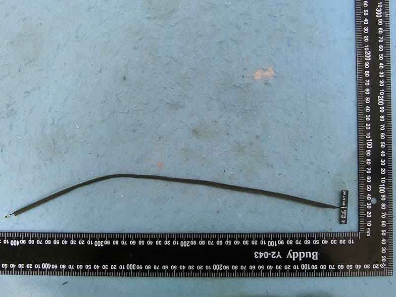
RAXAIOS65V
Nov 06, 2022HEOS 6.5 Platform Module
Equipment Class
DSS - Part 15 Spread Spectrum Transmitter