RAXWN4501F90AGigaset USB Adapter 54
Arcadyan Technology Corporation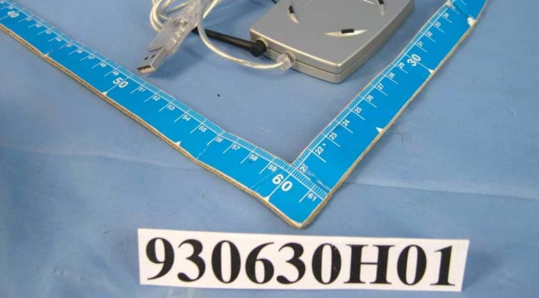
Click to zoom
Application Details
- Equipment Class
- DTS - Digital Transmission System
- Date of Grant
- Jul 19, 2004
- Application Purpose
- Original Equipment
- Date of Application
- Jul 19, 2004
- Equipment Note
- Gigaset USB Adapter 54
- Frequency Range
- 2412.00000000 - 2462.00000000
- Country
- Taiwan
Documents & Files
Document Text
Text extracted from the exhibit documents filed with the FCC. Open a document above to read the original.
Users Manual
s mobile Gigaset USB Adapter 54 Issued by Information and Communication mobile Haidenauplatz 1 D-81667 Munich © Siemens AG 2004 All rights reserved. Subject to availability. Rights of modification reserved. Siemens Aktiengesellschaft www.siemens-mobile.com/gigaset Ref.No.: A31008-E505-B104-1-PED1 cyanmagentayellowblack Liebreich Medienproduktion A31008-E505-B104-1-PED1 A31008-E505-B104-1-PED1 A31008-E505-B104-1-PED1 02.02.2004 10:05 Uhr Seite 1 1 Table of Contents Gigaset USB Adapter 54 / – / A31008-E505-B104-1-PED1 / USB54-AdapterIVZ.fm / 12.03.2004 Table of Contents Kurzbedienungsanleitung . . . . . . . . . . . . . . . . . . . . 3 Quick Start Guide . . . . . . . . . . . . . . . . . . . . . . . . . . . 11 Guide d'installation rapide . . . . . . . . . . . . . . . . . . . 19 Guida rapida . . . . . . . . . . . . . . . . . . . . . . . . . . . . . . . 27 Beknopte installatiehandleiding . . . . . . . . . . . . . . 35 Guía de instalación rápida . . . . . . . . . . . . . . . . . . . 43 Snabbguide . . . . . . . . . . . . . . . . . . . . . . . . . . . . . . . . 51 Kort brugsanvisning . . . . . . . . . . . . . . . . . . . . . . . . 59 Pikaohje . . . . . . . . . . . . . . . . . . . . . . . . . . . . . . . . . . 67 Hurtigguide . . . . . . . . . . . . . . . . . . . . . . . . . . . . . . . 75 Guia de instalação rápida . . . . . . . . . . . . . . . . . . . . 83 2 Gigaset USB Adapter 54 / – / A31008-E505-B104-1-PED1 / USB54-AdapterIVZ.fm / 12.03.2004 3 deutsch Gigaset USB Adapter 54 / deutsch / A31008-E505-B104-1-PED1 / qig_usb54.fm / 12.03.2004 Kurzbedienungsanleitung Diese Kurzbedienungsanleitung zeigt Ihnen, wie Sie die mitgelieferte Software installie- ren und den Gigaset USB Adapter 54 an Ihren PC anschließen. Detaillierte Informationen finden Sie in der Bedienungsanleitung in elektronischer Form auf der mitgelieferten CD-ROM und im Internet unter www.siemens-mobile.com/gigasetusbadapter54 . Warenzeichen Microsoft, Windows 98SE, Windows ME, Windows 2000, Windows XP und Internet Explorer sind registrierte Warenzeichen der Microsoft Corporation. Netscape, Netscape Navigator und Netscape Communicator sind registrierte Warenzei- chen der Netscape Communications Corporation. Sicherheitshinweise uDer Gigaset USB Adapter 54 kann den Betrieb von medizinischen Geräten beeinflus- sen. uHändigen Sie die Bedienungsanleitung und die CD-ROM mit aus, wenn Sie Ihren Gigaset USB Adapter 54 an Dritte weitergeben. Hinweise zum sicheren Betrieb Wenn Sie den Gigaset USB Adapter 54 auf Ihrem PC installiert und konfiguriert haben, sollten Sie Sicherheitseinstellungen am kabellosen Netzwerk vornehmen: uÄndern Sie die SSID für alle kabellosen Geräte Ihres Netzwerks. uVerschlüsseln Sie den Funkverkehr Ihres kabellosen Netzwerks. Packungsinhalt Die Verpackung enthält die folgenden Bestandteile: uein Gigaset USB Adapter 54 mit USB-Anschlusskabel und Dipol-Antenne ueine Installations-CD einschließlich Bedienungsanleitung und dem Dokument „Prak- tische Anwendungsfälle und Konfigurationsbeispiele“ udiese Kurzbedienungsanleitung 4 deutsch Gigaset USB Adapter 54 / deutsch / A31008-E505-B104-1-PED1 / qig_usb54.fm / 12.03.2004 Systemanforderungen Zum Betrieb benötigen Sie: ueinen PC mit mindestens 466 MHz und einem der folgenden Betriebssysteme: Windows 98SE, Windows ME, Windows 2000 oder Windows XP u64 MB RAM, mehr Arbeitsspeicher ist empfehlenswert umindestens 30 MB Festplattenkapazität ueinen freien USB-Anschluss uein CD-ROM-Laufwerk oder ein DVD-Laufwerk Grundlagen von Wireless LANs Um ein kabelloses Netzwerk (Ad-hoc-Netzwerk) aufzubauen, benötigen Sie für jeden PC, der an das Netz angeschlossen werden soll, einen kabellosen Netzwerkadapter, zum Beispiel den Gigaset USB Adapter 54, die Gigaset PC Card 54 oder die Gigaset PCI Card 54. Um ein Netzwerk mit kabellosen und gegebenenfalls kabelgebundenen Komponenten (Infrastruktur-Netzwerk) und mit Internet-Zugang aufzubauen, benötigen Sie zusätzlich einen Access Point, zum Beispiel den kabellosen Router Siemens Gigaset SE 505 dsl/ cable. Um das Netzwerk im Infrastruktur-Modus aufzubauen, gehen Sie wie folgt vor: 1. Installieren Sie zunächst den Gigaset USB Adapter 54 an einem PC. 2. Installieren Sie dann den Access Point. Dies ist in der Bedienungsanleitung des ent- sprechenden Geräts beschrieben. 3. Stellen Sie die Verbindung vom Gigaset USB Adapter 54 zum Access Point her. 4. Optional können Sie weitere PCs kabellos anschließen. i Beachten Sie bitte bei der Installation des Gigaset USB Adapters 54, dass die SSID (Service Set ID) aller kabellosen Netzwerkkomponenten iden- tisch sein muss. 5 deutsch Gigaset USB Adapter 54 / deutsch / A31008-E505-B104-1-PED1 / qig_usb54.fm / 12.03.2004 Ad-hoc-Netzwerk In einem Ad-hoc-Netzwerk werden über Funk Peer-to-Peer-Verbindungen zwischen PCs hergestellt. Ein Ad-hoc-Netzwerk wird von den Teilnehmern bei Bedarf spontan (ad hoc) aufgebaut. Infrastruktur-Netzwerk Im Infrastruktur-Netzwerk werden Verbindungen zwischen den Netzteilnehmern über einen Access Point (oder mehrere Access Points) hergestellt. Der Access Point, zum Bei- spiel den kabellosen Router Siemens Gigaset SE 505 dsl/cable, dient als Basis des kabel- losen Netzwerks. Er steuert die Verbindungen zwischen den angeschlossenen Teilneh- mern und kann außerdem die Verbindung von den mobilen Stationen eines kabellosen Netzwerks zu einem kabelgebundenen LAN (Ethernet) oder zum Internet herstellen. Installation Um ein Wireless LAN aufzubauen, gehen Sie wie folgt vor: 1. Installieren Sie die Software von der im Lieferumfang befindlichen CD-ROM, siehe „Installation” auf Seite 5. 2. Schließen Sie den Gigaset USB Adapter 54 erst dann an Ihren PC an, wenn das Instal- lationsprogramm Sie dazu aufordert. 3. Installieren Sie die Treiber. 4. Konfigurieren Sie das Netzwerk mit Hilfe des Gigaset WLAN Adapter Monitors. ! Stecken Sie den Stecker des USB-Kabels erst dann in eine Buchse Ihres PCs, wenn Sie von der Installations-Software dazu aufgefordert werden. i Beachten Sie bitte bei der Installation des …
Text truncated - open the document above for the full version.
External Photos
Page 1 CONSTRUCTION PHOTOS OF EUT Page 2
ID Label/Location Info
(Fig. 1) FCC ID: RAXWN4501F90A LABEL LOCATION Label
Internal Photos
Page 1 CONSTRUCTION PHOTOS OF EUT Page 2 Page 3
Operational Description
FCC ID: RAXWN4501F90A Report No. 930630H01 Operational Description This device is a Gigaset USB Adapter 54, the maximum data rate could be up to 54Mbps which OFDM technique will be applied. If the signal to noise radio is too poor which could not support 54Mbps, the 11Mbps data rate with CCK technique will be applied. The transmitter of the EUT (Gigaset USB Adapter 54) is powered by from host equipment. The antenna type used in this product are Chip antenna and dipole antenna without connector. The other instruction, please have a look at the users manual.
RF Exposure Info
FCC ID: RAXWN4501F90A ADT No.: SA930630H01 1 RF EXPOSURE REPORT REPORT NO.: SA930630H01 MODEL NO.: S30853-S1016-R107XX ACCORDING: FCC Guidelines for Human Exposure IEEE C95.1 APPLICANT: Arcadyan Technology Corporation ADDRESS: 4F, No. 9, Park Avenue II, Science-based Industrial Park, Hsinchu 300, Taiwan, R.O.C. ISSUED BY:Advance Data Technology Corporation LAB LOCATION:No. 81-1, Lu Liao Keng, 9 Ling, Wu Lung Tsuen, Chiung Lin Hsiang, Hsin Chu Hsien, Taiwan, R.O.C. FCC ID: RAXWN4501F90A ADT No.: SA930630H01 2 RF Exposure Measurement 1. Introduction In this document, we try to prove the safety of radiation harmfulness to the human body for our product. The limit for Maximum Permissible Exposure (MPE) specified in FCC 1.1310 is followed. The Gain of the antenna used in this product is measured in a Fully Anechoic Chamber (FAC) calibrated for antenna measurement in ADT, and also the maximum total power input to the antenna is measured. Through the Friis transmission formula and the maximum gain of the antenna, we can calculate the distance, away from the product, where the limit of MPE is reached. Although the Friis transmission formula is a far field assumption, the calculated result of that is an over-prediction for near field power density. We will take that as the worst case to specify the safety range. 2. RF Exposure Limit According to FCC 1.1310: The criteria listed in the following table shall be used to evaluate the environmental impact of human exposure to radio-frequency (RF) radiation as specified in 1.1307(b) LIMITS FOR MAXIMUM PERMISSIBLE EXPOSURE (MPE) Frequency Range (MHz) Electric Field Strength (V/m) Magnetic Field Strength (A/m) Power Density (mW/cm 2 ) Average Time (minutes) (A)Limits For Occupational / Control Exposures 300-1500......F/3006 1500-100,000......56 (B)Limits For General Population / Uncontrolled Exposure 300-1500......F/15006 1500-100,000......1.030 F = Frequency in MHz FCC ID: RAXWN4501F90A ADT No.: SA930630H01 3 3. Friis Formula Friis transmission formula : Pd = (Pout*G) / (4*pi*r 2 ) where Pd = power density in mW/cm 2 Pout = output power to antenna in mW G = gain of antenna in linear scale Pi = 3.1416 R = distance between observation point and center of the radiator in cm Pd is the limit of MPE, 1 mW/cm 2 . If we know the maximum Gain of the antenna and the total power input to the antenna, through the calculation, we will know the MPE value at distance 20cm. Ref. : David K. Cheng, Field and Wave Electromagnetics, Second Edition, Page 640, Eq. (11-133). 4. EUT Operating condition The software provided by Manufacturer enabled the EUT to transmit and receive data at lowest, middle and highest channel individually. 5. Classification The antenna of this product, under normal use condition, is at least 20cm away from the body of the user. Warning statement to the user for keeping at least 20cm or more separation distance with the antenna should be included in users manual. So, this device is classified as Mobile Device FCC ID: RAXWN4501F90A ADT No.: SA930630H01 4 6. Test Results 6.1 Antenna Gain The maximum Gain measured in Fully Anechoic Chamber are 2.0dBi or 1.58489 (numeric) 6.2 Output Power Into Antenna & RF Exposure value at distance 20cm: For Part 802.11b: Channel Channel Frequency (MHz) Output Power to Antenna (mW) Power Density (mW/cm 2 ) Limit of Power Density (mW/cm 2 ) 12412134.8962880.0425333051.0 62437173.07800830.0547935111.0 112462138.0384260.0435240331.0 For Part 802.11g: Channel Channel Frequency (MHz) Output Power to Antenna (mW) Power Density (mW/cm 2 ) Limit of Power Density (mW/cm 2 ) 1241287.0963590.0274618081.0 62437107.1519310.0337854051.0 11246283.17637710.0262258231.0
Test Report
FCC ID: RAXWN4501F90A Report No.: RF930630H011 Issued: Jul. 13, 2004 FCC TEST REPORT REPORT NO.:RF930630H01 MODEL NO.:S30853-S1016-R107XX RECEIVED:Jul. 01, 2004 TESTED:Jul. 05 to 07, 2004 APPLICANT: Arcadyan Technology Corporation ADDRESS: 4F, No. 9, Park Avenue II, Science-based Industrial Park, Hsinchu 300, Taiwan, R.O.C. ISSUED BY:Advance Data Technology Corporation LAB LOCATION:No. 81-1, Lu Liao Keng, 9 Ling, Wu Lung Tsuen, Chiung Lin Hsiang, Hsin Chu Hsien, Taiwan, R.O.C. This test report consists of 59 pages in total. It may be duplicated completely for legal use with the approval of the applicant. It should not be reproduced, except in full, without the written approval of our laboratory. The client should not use it to claim product endorsement by CNLA, or any government agencies. The test results in the report only apply to the tested sample. 0536 ILAC MRA FCC ID: RAXWN4501F90A Report No.: RF930630H012 Issued: Jul. 13, 2004 Table of Contents 1CERTIFICATION ........................................................................................... 4 2SUMMARY OF TEST RESULTS................................................................... 5 3GENERAL INFORMATION ........................................................................... 6 3.1GENERAL DESCRIPTION OF EUT.............................................................. 6 3.2DESCRIPTION OF TEST MODES................................................................ 7 3.3GENERAL DESCRIPTION OF APPLIED STANDARDS ............................... 7 3.4DESCRIPTION OF SUPPORT UNITS.......................................................... 8 3.5CONFIGURATION OF SYSTEM UNDER TEST ........................................... 8 4TEST TYPES AND RESULTS....................................................................... 9 4.1CONDUCTED EMISSION MEASUREMENT ................................................ 9 4.1.1LIMITS OF CONDUCTED EMISSION MEASUREMENT ............................. 9 4.1.2TEST INSTRUMENTS .................................................................................. 9 4.1.3TEST SETUP .............................................................................................. 10 4.1.4EUT OPERATING CONDITIONS.................................................................11 4.1.5TEST RESULTS.......................................................................................... 12 4.2Radiated Emission Measurement ............................................................... 14 4.2.1LIMITS OF RADIATED EMISSION MEASUREMENT ................................ 14 4.2.2TEST INSTRUMENTS ................................................................................ 15 4.2.3TEST PROCEDURES................................................................................. 16 4.2.4TEST SETUP .............................................................................................. 17 4.2.5EUT OPERATING CONDITIONS................................................................ 17 4.2.6TEST RESULTS.......................................................................................... 18 4.2.7TEST RESULTS – DSSS ............................................................................ 19 4.2.8TEST RESULTS - OFDM ............................................................................ 22 4.36dB BANDWIDTH MEASUREMENT .......................................................... 25 4.3.1LIMITS OF 6dB BANDWIDTH MEASUREMENT........................................ 25 4.3.2TEST INSTRUMENTS ................................................................................ 25 4.3.3TEST PROCEDURE ................................................................................... 26 4.3.4TEST SETUP .............................................................................................. 26 4.3.5EUT OPERATING CONDITIONS................................................................ 26 4.3.6TEST RESULTS-DSSS............................................................................... 27 4.3.7TEST RESULTS-OFDM .............................................................................. 31 4.4MAXIMUM PEAK OUTPUT POWER .......................................................... 35 4.4.1LIMITS OF MAXIMUM PEAK OUTPUT POWER MEASUREMENT ........... 35 4.4.2TEST INSTRUMENTS ................................................................................ 35 FCC ID: RAXWN4501F90A Report No.: RF930630H013 Issued: Jul. 13, 2004 4.4.3TEST PROCEDURES................................................................................. 36 4.4.4TEST SETUP .............................................................................................. 36 4.4.5EUT OPERATING CONDITIONS................................................................ 36 4.4.6TEST RESULTS- DSSS.............................................................................. 37 4.4.7TEST RESULTS- OFDM ............................................................................. 38 4.5POWER SPECTRAL DENSITY MEASUREMENT...................................... 39 4.5.1LIMITS OF POWER SPECTRAL DENSITY MEASUREMENT ................... 39 4.5.2TEST INSTRUMENTS ................................................................................ 39 4.5.3TEST PROCEDURE ................................................................................... 40 4.5.4TEST SETUP .............................................................................................. 40 4.5.5EUT OPERATING CONDITIONS................................................................ 40 4.5.6TEST RESULTS-DSSS............................................................................... 41 4.5.7TEST RESULTS-OFDM .............................................................................. 45 4.6BAND EDGES MEASUREMENT ................................................................ 49 4.6.1LIMITS OF BAND EDGES MEASUREMENT ............................................. 49 4.6.2TEST INSTRUMENTS ...................…
Text truncated - open the document above for the full version.
Test Report
Report No. 930630H01 1 The Measurement of Conducted Spurious Emissions CONDUCTED SPURIOUS EMISSIONS MEASUREMENT 1. LIMITS OF CONDUCTED SPURIOUS EMISSIONS EASUREMENT Below 20dB of the highest emission level of operating band (in 100KHz Resolution Bandwidth, see Section 15.247(c)). Emissions which fall in the restricted bands, as defined in Section 15.205(a), must also comply with the limits specified in Section 15.209(a) (see Section 15.205(c)). 2. TEST INSTRUMENTS Description & ManufacturerModel No.Serial No.Calibrated Until R&S SPECTRUM ANALYZERFSP40100036Nov. 27, 2005 High pass filter 2.4G WHK3.1/18G- 10SS SN4Jun. 08, 2005 NOTE: 1.The calibration interval of the above test instruments is 12 months and the calibrations are traceable to NML/ROC and NIST/USA. 3. TEST PROCEDURE The transmitter output was connected to the spectrum analyzer via a low lose cable. Set both RBW and VBW of spectrum analyzer to 100 kHz with suitable frequency span including 100 kHz bandwidth from band edge. The band edges was measured and recorded. Report No. 930630H01 2 4. TEST SETUP 5. EUT OPERATING CONDITIONS The software provided by client to enable the EUT under transmission condition continuously at lowest, middle and highest channel frequencies individually. EUT SPECTRUM ANALYZER Report No. 930630H01 3 TEST RESULTS – For 802.11b The spectrum plots are attached on the following 2 pages. It shows compliance with the requirement in part 15.247(C),.15.205 and 15.209. Report No. 930630H01 4 Ch1 Report No. 930630H01 5 Ch11 Report No. 930630H01 6 TEST RESULTS – For 802.11g The spectrum plots are attached on the following 2 pages. It shows compliance with the requirement in part 15.247(C),.15.205 and 15.209. Report No. 930630H01 7 Ch1 Report No. 930630H01 8 Ch11
Test Setup Photos
FCC ID: RAXWN4501F90A Report No.: RF930630H0157 Issued: Jul. 13, 2004 5 PHOTOGRAPHS OF THE TEST CONFIGURATION CONDUCTED EMISSION TEST FCC ID: RAXWN4501F90A Report No.: RF930630H0158 Issued: Jul. 13, 2004 RADIATED EMISSION TEST
Contact Information
Applicant
Simon Liu(Manager)
Technical Contact
Advance Data Technology CorporationEric Lin
[email protected]+88635935343
81-1 Luliaoken, 9th Lin, Wulung Tsuen Chiunglin · Hsinchu · Taiwan
Test Firm
Bureau Veritas CPS (H.K.) Ltd. Taoyuan BranchRichard Chen
Technical Specifications
| # | Rule Parts | Frequency Range | Power Output |
|---|---|---|---|
| 1 | 15C | 2.41 GHz - 2.46 GHz | 174.00 mW |
Other Applications from Arcadyan Technology Corporation
RAXWE6204430
Jan 27, 2024Wi-Fi Extender
Equipment Class
DTS - Digital Transmission System
RAXAIOS7
Nov 08, 2023HEOS 7.0 Platform Module
Equipment Class
NII - Unlicensed National Information Infrastructure TX
RAXWR3210
Jul 13, 2023Standalone Router
Equipment Class
DTS - Digital Transmission System
RAXWE7224443
Jan 11, 2023Verizon Wi-Fi Extender
Equipment Class
6PP - 15E 6 GHz Subordinate Indoor Device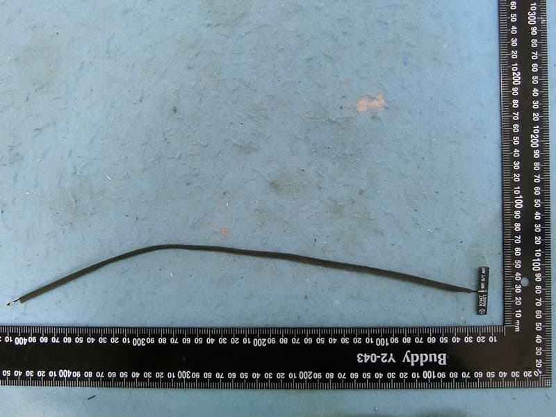
RAXAIOS65V
Nov 06, 2022HEOS 6.5 Platform Module
Equipment Class
DSS - Part 15 Spread Spectrum Transmitter