RB90601Licensed Transmitter
Microcell SA, Lux., Swiss Branch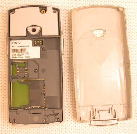
Click to zoom
Application Details
- Equipment Class
- PCE - PCS Licensed Transmitter held to ear
- Date of Grant
- Dec 18, 2003
- Application Purpose
- Original Equipment
- Date of Application
- Dec 18, 2003
- Equipment Note
- Licensed Transmitter
- Frequency Range
- 1850.20000000 - 1909.80000000
- Country
- Finland
Documents & Files
Document Text
Text extracted from the exhibit documents filed with the FCC. Open a document above to read the original.
Users Manual
1 DRAFT MyOrigo mydevice Z1 Second Edition This document is provided "as is" without warranty of any kind, either expressed or implied, including, but not limited to, the implied warranties of merchant ability, fitness for a particular purpose, or non-infringement. This manual could include technical or other inaccuracies or typographical errors. Changes are periodically added to the information herein; these changes will be incorporated in a new edition of this manual. MyOrigo Oy, Ltd. reserves the right to make improvements and /or changes in the product(s) described in this manual at any time. ©MyOrigo Oy, Ltd. 2003 All rights reserved. Issued by: MyOrigo Oy, Ltd. Kasarmintie 28 H25 90230 Oulu Finland Publication Number: intent is a registered trademark of Tao Group Ltd. espial Draft_Releasev.2.book Page 1 Tuesday, October 28, 2003 2:42 PM 2Introduction DRAFT Introduction The MyOrigo mydevice Z1 is a triple band phone and can be operated on E- GSM 900, GSM 1800 and GSM 1900 networks, which means that you are able to use the device in many regions across the world. The device has a large colour display that is also a touch screen with feed- back when you press the screen. This feedback from the touch screen is referred to as Haptitouch. The device has a built in digital camera which can be used to take photos. In the device are motion sensors that can be used to control certain move- ments and functions in the device, like mirroring and zooming the views. The device supports GPRS (General Packet Radio Services) which means that you can make fast data connections. MMS, E-mail messaging and Internet browsing are supported in the device through GPRS connections. Draft_Releasev.2.book Page 2 Tuesday, October 28, 2003 2:42 PM Getting Started3 DRAFT Getting Started Overview 1.Function Key A2.Function Key B 3.Infrared Port4.LED Indicator 5.Earpiece6.Haptitouch Screen 7.Microphone8.Camera Lens 9.Battery Cover Release10.Mini USB Data Cable Connector 11.Headset Connector Port12.Charger Connector Port 2 3 5 8 6 9 7 11 12 1 7 4 10 Draft_Releasev.2.book Page 3 Tuesday, October 28, 2003 2:42 PM 4Getting Started DRAFT Inserting the Battery Removing the Battery Cover 1.With your fingernail, pull the battery cover latch downwards 2.Lift the cover slightly at the battery cover latch end and gently slide upwards to release the battery cover from the upper corner release catches. Replacing the Battery Cover Repeat the Removing the battery Cover in the opposite order. Draft_Releasev.2.book Page 4 Tuesday, October 28, 2003 2:42 PM Getting Started5 DRAFT Attaching the battery 1.Place the battery into the back of the phone, with the golden connectors facing down. 2.Push the battery down at the bottom and then slide up so that the battery is locked into position by means of the battery locking pins. Removing the battery 1.With your finger nail pull down and lift out the battery. NOTE:Always switch the phone off before removing the battery. Inserting your SIM Card 1.If the SIM card is attached to the plastic surround card, then first snap out the card pushing it out at the snap points. Draft_Releasev.2.book Page 5 Tuesday, October 28, 2003 2:42 PM 6Getting Started DRAFT Inserting the SIM card in the device 1.Insert the SIM card with the golden contacts facing down as shown in the picture. Removing the SIM card from the device 1.Press lightly on the card and slide out in the opposite direction from inserting. Inserting the Multimedia Card 1.Insert the MultiMedia card with the golden contacts facing down and the cut corner at the bottom right, as shown in the picture. Draft_Releasev.2.book Page 6 Tuesday, October 28, 2003 2:42 PM Getting Started7 DRAFT Removing the MultiMedia card 1.Press lightly on the card and slide out in the opposite direction from inserting. Charging the device 1.Connect the charger to the mains socket. 2.Connect the other end of the charger lead to the bottom of the device. When the device is switched off and the charger is connected, Charging... is displayed on the screen. If the device is switched on when the charger is connected, Charging will be briefly displayed. The battery meter level in the status field shows the charged state of the battery. When charging, this will be animated to show that the battery is being charged. When the battery level is low, the device will give a warning signal and Battery Low, Recharge battery will be briefly displayed. NOTE:You can use the device whilst the battery is being charged. How- ever, this lengthens the charging time. Do not connect any chargers to the device other than the charger model that was provided in the sales package. Full Empty Draft_Releasev.2.book Page 7 Tuesday, October 28, 2003 2:42 PM 8Getting Started DRAFT LED Indication Lights Normal blinking is when the LED flashes every 2 seconds. Slow blinking is when the LED flashes three times slower than normal. Green LED indications • Continuously on - the device is in the start up procedure. •Normal blinking - when a new message is received, missed call etc. whilst the device is in standby mode. •Slow blinking - when the device is on and in standby mode. Red LED indications • Continuously on - the device is in the shut down procedure. •Normal blinking - when the battery is low Switching the device On and Off Before you try to turn on the power, follow the SIM card and Battery insert procedure. See..... Tu r n i n g o n t h e d e v i c e 1.Press and hold the function keys A & B simultaneously for approximately 2 seconds until the display comes to life. 2.Press the icon on the screen to select the mode you wish to use the device in. Key AKey B Draft_Releasev.2.book Page 8 Tuesday, October 28, 2003 2:42 PM Getting Started9 DRAFT Aeroplane Mode The aeroplane mode allows you to use the device without any voice calls and data connections. You may be asked to provide a Device lock code, the factory set device lock code is 0000. To change this code, switch this function off see... 1.Enter your …
Text truncated - open the document above for the full version.
External Photos
External photographs of the equipment Photograph no.:1 Photograph no.:2 Photograph no.:3 Photograph no.:4 GSM triple-band antenna
ID Label/Location Info
Type label spec. Ver 0.2 21.May.2003 Confidential Page 1 of 9 © Microcell Ltd The contents of this document are confidential and must not be disclosed wholly or in part to any third party without the prior written consent of Microcell Ltd. MYORIGO Type Label Specification Author Kari Lehto Status Draft Version 0.2 MICROCELL Ltd, Kaarnatie 38, FIN-90530, OULU, FINLAND Type label spec. Ver 0.2 21.May.2003 Confidential Page 2 of 9 © Microcell Ltd Change History Version Date Handled / Approved by Status More Information 0.1 19.5.2003 Pertti Paaso draft 0.2 21.05.2003 Pertti Paaso draft Images changed Type label spec. Ver 0.2 21.May.2003 Confidential Page 3 of 9 © Microcell Ltd TABLE OF CONTENTS Glossary ..........................................................................................................................4 1 GENERAL information ..............................................................................................5 1.1 SCOPE................................................................................................................5 1.2 CONDITIONS......................................................................................................5 1.3 LABEL MATERIAL AND VENDOR.....................................................................5 1.3.1 Label material in label roll .............................................................................5 1.3.2 Gap between labels in label roll....................................................................6 1.4 RIBBON FOR TYPE LABELS.............................................................................6 1.5 LABEL SIZE ........................................................................................................6 1.6 LABEL IMAGES ..................................................................................................7 2 REQUIRMENTS........................................................................................................8 2.1 REPAIR FIELD FORMAT ...................................................................................8 2.2 MANUFACTURING FIELD FORMAT.................................................................8 2.3 IMEI FIELD..........................................................................................................8 2.4 PRODUCT CODE FIELD....................................................................................8 2.5 TYPE FIELD........................................................................................................8 2.6 PSN FIELD..........................................................................................................9 2.7 HWID FIELD .......................................................................................................9 2.8 BUILD FIELD ......................................................................................................9 2.9 SERIAL NUMBER...............................................................................................9 Type label spec. Ver 0.2 21.May.2003 Confidential Page 4 of 9 © Microcell Ltd GLOSSARY Type label spec. Ver 0.2 21.May.2003 Confidential Page 5 of 9 © Microcell Ltd 1 GENERAL INFORMATION This is the master document for Orange phone type labels. Label roll, label size, used ribbon and all label fields are described in this document. 1.1 SCOPE This document describes the requirement of a type label. 1.2 CONDITIONS This document is applicable for Orange mobile phone. This document is general and implementation must be decided within each project. Customer Service is responsible for creating Type Label Specifications document and agreeing the content of it with Customer’s After Sales and Customer Service departments. Manufacturing / Production Testing is responsible for creating Type label printing SW as a part of After Sales Service SW and other production related testing SW according this document for Production Line of the product. 1.3 LABEL MATERIAL AND VENDOR Label material is for phone type label is Brady B-7575 methalized polyester (thermal printing) with diamond print safety print background. For PROTO phone labels, pre-series phones, some other materials can be used also like Brady ELAT-34-747 (laser printing) or similar. Vendor for label materials is Tele-Exxi Oy Ab, Espoo. Contact person is Matti Moilanen. 1.3.1 Label material in label roll Labels must be delivered in label rolls. Label roll must be winded like demonstrated on the Image below. Type label spec. Ver 0.2 21.May.2003 Confidential Page 6 of 9 © Microcell Ltd 1.3.2 Gap between labels in label roll Label gap must be standard to be able to print out the labels in production with proper information. A gap between two labels in the same label roll should be always the same. It is recommended to use 3mm gap between the labels. 1.4 RIBBON FOR TYPE LABELS Ink ribbon material for type labels is R7963, W=40 mm. Both type labels, CE Approved (China) label and CE Approved label uses this ribbon. Vendor for ribbon material is Tele-Exxi Oy Ab, Espoo. Contact person is Matti Moilanen. 1.5 LABEL SIZE The following information describes the size of the type label. 3mm 21.75 mm 18.75 mm 11.75 mm 29.75 mm Type label spec. Ver 0.2 21.May.2003 Confidential Page 7 of 9 © Microcell Ltd 1.6 LABEL IMAGES NOTE: Example image is not in real size not in final format. Type label spec. Ver 0.2 21.May.2003 Confidential Page 8 of 9 © Microcell Ltd 2 REQUIRMENTS Three different kind of labels (markings on labels) are needed for 1) Proto phones, 2) mass- approved and 3) type approved phones. Label material is the same for proto-, mass- and type approved phones. 2.1 REPAIR FIELD FORMAT The repair field consists of 6-digits and shall be given as RYWWZZ. Note: Factory made phones repair field is with R00000 status . When phone is being repaired in Service Center(s) R00000 is changed. R Repaired States a repaired and/or refurbished unit Y Year Year of repair, only two last digits of the year WW Week Week of …
Text truncated - open the document above for the full version.
RF Exposure Info
CETECOM ICT Services GmbH Untertuerkheimer Str. 6-10, 66117 Saarbruecken, GermanyPhone: +49 (0) 681 598-0Fax: -8475 SAR-Laboratory Phone: +49 (0) 681 598-8454 . As of June 26, 2003Page 1 of 32 Accredited testing laboratory DAR registration number: TTI-P-G 166/98 Federal Motor Transport Authority (KBA) DAR registration number: KBA-P 00070-97 Appendix to the Report 4-1005-01-01/03 Calibration Data, Phantom Certificate and detail Information of the DASY 3 System Test specification : CETECOM ICT Services GmbH Calibration Data and Phantom Information; Report No.: 4-1005-01-01/03 As of June 26, 2003Page 2 of 32 Table of Content 1Calibration report “Probe ET3DV6”.............................................................................................................................................3 2Calibration report “1900 MHz System validation dipole”.......................................................................................................14 3Calibration certificate of Data Aquisition Unit (DAE)..............................................................................................................24 4Certificate of Conformity “SAM Twin Phantom V4.0/V4.0C”................................................................................................25 5Application Note Validation and system Check........................................................................................................................27 CETECOM ICT Services GmbH Calibration Data and Phantom Information; Report No.: 4-1005-01-01/03 As of June 26, 2003Page 3 of 32 1 Calibration report “Probe ET3DV6” CETECOM ICT Services GmbH Calibration Data and Phantom Information; Report No.: 4-1005-01-01/03 As of June 26, 2003Page 4 of 32 CETECOM ICT Services GmbH Calibration Data and Phantom Information; Report No.: 4-1005-01-01/03 As of June 26, 2003Page 5 of 32 CETECOM ICT Services GmbH Calibration Data and Phantom Information; Report No.: 4-1005-01-01/03 As of June 26, 2003Page 6 of 32 CETECOM ICT Services GmbH Calibration Data and Phantom Information; Report No.: 4-1005-01-01/03 As of June 26, 2003Page 7 of 32 CETECOM ICT Services GmbH Calibration Data and Phantom Information; Report No.: 4-1005-01-01/03 As of June 26, 2003Page 8 of 32 CETECOM ICT Services GmbH Calibration Data and Phantom Information; Report No.: 4-1005-01-01/03 As of June 26, 2003Page 9 of 32 CETECOM ICT Services GmbH Calibration Data and Phantom Information; Report No.: 4-1005-01-01/03 As of June 26, 2003Page 10 of 32 CETECOM ICT Services GmbH Calibration Data and Phantom Information; Report No.: 4-1005-01-01/03 As of June 26, 2003Page 11 of 32 CETECOM ICT Services GmbH Calibration Data and Phantom Information; Report No.: 4-1005-01-01/03 As of June 26, 2003Page 12 of 32 CETECOM ICT Services GmbH Calibration Data and Phantom Information; Report No.: 4-1005-01-01/03 As of June 26, 2003Page 13 of 32 CETECOM ICT Services GmbH Calibration Data and Phantom Information; Report No.: 4-1005-01-01/03 As of June 26, 2003Page 14 of 32 2 Calibration report “1900 MHz System validation dipole” CETECOM ICT Services GmbH Calibration Data and Phantom Information; Report No.: 4-1005-01-01/03 As of June 26, 2003Page 15 of 32 CETECOM ICT Services GmbH Calibration Data and Phantom Information; Report No.: 4-1005-01-01/03 As of June 26, 2003Page 16 of 32 CETECOM ICT Services GmbH Calibration Data and Phantom Information; Report No.: 4-1005-01-01/03 As of June 26, 2003Page 17 of 32 CETECOM ICT Services GmbH Calibration Data and Phantom Information; Report No.: 4-1005-01-01/03 As of June 26, 2003Page 18 of 32 CETECOM ICT Services GmbH Calibration Data and Phantom Information; Report No.: 4-1005-01-01/03 As of June 26, 2003Page 19 of 32 CETECOM ICT Services GmbH Calibration Data and Phantom Information; Report No.: 4-1005-01-01/03 As of June 26, 2003Page 20 of 32 CETECOM ICT Services GmbH Calibration Data and Phantom Information; Report No.: 4-1005-01-01/03 As of June 26, 2003Page 21 of 32 CETECOM ICT Services GmbH Calibration Data and Phantom Information; Report No.: 4-1005-01-01/03 As of June 26, 2003Page 22 of 32 CETECOM ICT Services GmbH Calibration Data and Phantom Information; Report No.: 4-1005-01-01/03 As of June 26, 2003Page 23 of 32 CETECOM ICT Services GmbH Calibration Data and Phantom Information; Report No.: 4-1005-01-01/03 As of June 26, 2003Page 24 of 32 3 Calibration certificate of Data Aquisition Unit (DAE) CETECOM ICT Services GmbH Calibration Data and Phantom Information; Report No.: 4-1005-01-01/03 As of June 26, 2003Page 25 of 32 4 Certificate of Conformity “SAM Twin Phantom V4.0/V4.0C” CETECOM ICT Services GmbH Calibration Data and Phantom Information; Report No.: 4-1005-01-01/03 As of June 26, 2003Page 26 of 32 CETECOM ICT Services GmbH Calibration Data and Phantom Information; Report No.: 4-1005-01-01/03 As of June 26, 2003Page 27 of 32 5 Application Note Validation and system Check 5.1.1.1 Purpose of validation The Validation and system check verify that the system operates within ist specifications. System and operator errors can be detected and corrected. It is recommended that the validation be performed prior to any usage of the system in order to guarantee reproducible results. The measurement of the Specific Absorption Rate (SAR) is a complicated task and the resultdepends on the proper functioning of many components and the correct settings of manyparameters. Faulty results due to drift, failures or incorrect parameters might not berecognized, since they often look similar in distribution to the correct ones. The DosimetricAssessment System DASY3 incorporates a validation procedure to test the properfunctioning of the system. The system validation uses normal SAR measurements in asimplified setup (the flat phantom section of the Generic Twin Phantom) with a wellcharacterized source (a matched dipole of a specified distance). This setup was selected to give a high sensitivity to all parameters that might fail or vary over tim…
Text truncated - open the document above for the full version.
RF Exposure Info
CETECOM ICT Services GmbH Untertuerkheimer Str. 6-10, 66117 Saarbruecken, GermanyPhone: +49 (0) 681 598-0Fax: -8475 SAR-Laboratory Phone: +49 (0) 681 598-8454 . As of June 26, 2003Page 1 of 54 Accredited testing laboratory DAR registration number: TTI-P-G 166/98 Federal Motor Transport Authority (KBA) DAR registration number: KBA-P 00070-97 Test report no. : 4-1005-01-01/03 Type identification: SB0601 Test specification : Draft IEEE Std 1528-200X FCC-ID: ?????? Test specification : CETECOM ICT Services GmbH Test report no.: 4-1005-01-01/03 As of June 26, 2003Page 2 of 54 Table of Contents 1General Information............................................................................................................................................................... 3 1.1Notes .............................................................................................................................................................................. 3 1.1.1Statement of Compliance ....................................................................................................................................... 3 1.2Testing laboratory .......................................................................................................................................................... 4 1.3Details of applicant ........................................................................................................................................................ 4 1.4Application details ......................................................................................................................................................... 4 1.5Test item ........................................................................................................................................................................ 5 1.6Test specification(s) ....................................................................................................................................................... 6 1.6.1RF exposure limits ................................................................................................................................................. 6 2Technical test ......................................................................................................................................................................... 7 2.1Summary of test results.................................................................................................................................................. 7 2.2Test environment ........................................................................................................................................................... 7 2.3Measurement and test set-up.......................................................................................................................................... 7 2.4Measurement system...................................................................................................................................................... 8 2.4.1System Description ................................................................................................................................................ 8 2.4.2Test environment ................................................................................................................................................... 9 2.4.3Probe description ................................................................................................................................................... 9 2.4.4Phantom description............................................................................................................................................. 10 2.4.5Device holder description .................................................................................................................................... 10 2.4.6Scanning procedure.............................................................................................................................................. 11 2.4.7Spatial Peak SAR Evaluation............................................................................................................................... 12 2.4.8Data Storage and Evaluation................................................................................................................................ 13 2.4.9Test equipment utilized ........................................................................................................................................ 15 2.4.10Tissue simulating liquids : dielectric properties................................................................................................... 16 2.4.11Tissue simulating liquids : parameters ................................................................................................................. 17 2.4.12Measurement uncertainties .................................................................................................................................. 18 2.4.13System validation................................................................................................................................................. 19 2.4.14Validation procedure............................................................................................................................................ 20 2.5Test results (Head and Body SAR) .............................................................................................................................. 21 2.5.1Description of test procedures.............................................................................................................................. 21 Annex 1System performance verification ............................................................................................................................. 22 Annex 2Measurement results (printout from DASY TM )................…
Text truncated - open the document above for the full version.
Test Report
CETECOM ICT Services GmbH Radio Satellite Communication Untertürkheimer Straße 6-10 . D-66117 SaarbrückenTelefon: +49 (0)681 598-9100Telefax: -9075 RSC14issue test report consist of 78 PagesPage 1 (78) BLUETOOTH TM is a trademark owned by Bluetooth SIG, Inc. and licensed to CETECOM Recognized by the Federal Communications Commission and Industry Canada Anechoic chamber registration no. 90462 (FCC) Anechoic chamber registration no. 3463 (IC) TCB ID: DE 0001 Accredited by the German Accreditation Council DAR–Registration Number TTI–P–G 166/98 Independent ETSI compliance test house ETSI Accredited Bluetooth™ Test Facility (BQTF) Test Report No.: 4_1005-01-02/03 FCC Part 24 SB0601 FCC ID: RB90601 CETECOM – ICT Services GmbH Untertürkheimerstr. 6-10 66117 Saarbrücken, Germany Telephone: + 49 (0) 681 / 598-0 Fax: + 49 (0) 681 / 598-9075 CETECOM ICT Services GmbH Test Report No.: 4_1005-01-02/03Issue Date: 2003-06-26Page 2 (78) Table of Contents 1 General information 1.1 Notes 1.2 Testing laboratory 1.3 Details of applicant 1.4 Application details 1.5 Test item 1.6 Test Specifications 2 Technical test 2.1 Summary of test results 2.2 Test report CETECOM ICT Services GmbH Test Report No.: 4_1005-01-02/03Issue Date: 2003-06-26Page 3 (78) 1 General information 1.1 Notes The test results of this test report relate exclusively to the test item specified in 1.5. The CETECOM ICT Services GmbH does not assume responsibility for any conclusions and generalizations drawn from the test results with regard to other specimens or samples of the type of the equipment represented by the test item. The test report may only be reproduced or published in full. Reproduction or publication of extracts from the report requires the prior written approval of the CETECOM ICT Services GmbH. Technical responsibility for area of testing : 2003-06-26RSC 8414 Ames H. DateSectionNameSignature Technical responsibility for area of testing : 2003-06-26RSC8412Hausknecht D. DateSectionNameSignature CETECOM ICT Services GmbH Test Report No.: 4_1005-01-02/03Issue Date: 2003-06-26Page 4 (78) 1.2 Testing laboratory CETECOM ICT Services GmbH Untertürkheimer Straße 6 - 10 66117 Saarbrücken Germany Telephone: + 49 681 598 - 9100 Telefax : + 49 681 598 - 9075 E-mail: [email protected] Internet: www.cetecom-ict.de Accredited testing laboratory DAR-registration number : TTI-P-G-166/98-30 Accredited Bluetooth TM Test Facility (BQTF) BLUETOOTH TM is a trademark owned by Bluetooth SIG, Inc. and licensed to CETECOM 1.3 1.3Details of applicant Name : Microcell Oy Street : Kaarnatie 38 City : 90530 Oulu Country : Finland Telephone : +358-40-8348-473 Telefax : Contact : Mr. Mikko Laamanen Telephone : +358-40-8348-473 e-mail: [email protected] 1.3 Application details Date of receipt of application : 2003-06-17 Date of receipt of test item : 2003-06-17 Date of test : 2003-06-17 to 2003-06-26 CETECOM ICT Services GmbH Test Report No.: 4_1005-01-02/03Issue Date: 2003-06-26Page 5 (78) 1.4 Test item Type of equipment : GSM Mobile Phone ( here 1900 MHz) Type designation: SB0601 Manufacturer:Applicant Street: City: Country: Serial number:IMEI : 004400.60.277163.0 Additional information: Frequency :1850 – 1910 MHz Type of modulation:300KGXW Number of channels :300 (PCS1900) Antenna:Integral antenna Power supply:3,8V DC Li-Ion Output power GSM 1900 : cond : 30.0 dBm Peak , ERP: 27.35 dBm (Burst); EIRP: 29.45 dBm (Burst) Type of equipment:Temperature range : -30°C - +60°C FCC – ID : RB90601 FCC registration number : Hardware : Software: 1.5 Test specifications: FCC Part 24 FCC Part 15 CETECOM ICT Services GmbH Test Report No.: 4_1005-01-02/03Issue Date: 2003-06-26Page 6 (78) 2 Technical test For Part 24 we use the substitution method ( TIA/EIA 603). All measurements in this report are done in GSM mode. Device is able to transmit data in GPRS mode also. But because the current measurements are performed in PEAK mode no other results from GPRS mode are possible. The only different is the modulation average power, which is 3 dB higher (if it is possible to use 2 timeslots in the Up-link ). 2.1Summary of test results No deviations from the technical specification(s) were ascertained in the course of the tests performed. FINAL VERDICT: PASS CETECOM ICT Services GmbH Test Report No.: 4_1005-01-02/03Issue Date: 2003-06-26Page 7 (78) 2.2Test Report TEST REPORT Test Report No. : 4_1005-01-02/03 CETECOM ICT Services GmbH Test Report No.: 4_1005-01-02/03Issue Date: 2003-06-26Page 8 (78) TEST REPORT REFERENCE LIST OF MEASUREMENTS PARAMETER TO BE MEASURED PAGE Part PCS 1900 POWER OUTPUT SUBCLAUSE § 24.2329 FREQUENCY STABILITY SUBCLAUSE § 24.23511 EMISSIONS LIMITS §24.23814 VALID FOR ALL THREE CHANNELS 19 BLOCK EDGE COMPLIANCE FOR BLOCK A AND C 35 OCCUPIED BANDWIDTH §2.98947 CONDUCTED EMISSIONS § 15.20754 ADDITIONAL MEASUREMENTS FOR THE ANCILLARY EQUIPMENT PART 15.109 57 TEST EQUIPMENT AND ANCILLARIES USED FOR TESTS64 TEST SITE66 PHOTOGRAPHS OF THE EQUIPMENT68 INTERNAL PHOTOGRAPHS OF THE EQUIPMENT72 CETECOM ICT Services GmbH Test Report No.: 4_1005-01-02/03Issue Date: 2003-06-26Page 9 (78) REFERENCE NUMBER(S) OF TEST EQUIPMENT USED (for reference numbers see test equipment listing) 64 POWER OUTPUT SUBCLAUSE § 24.232 Summery: This paragraph contains both average , peak output powers and EIRP measurements for the mobile station. In all cases, the peak output power is within the required mask (this mask is specified in the JTC standards, TIA PN3389 Vol. 1 Chap 7, and is no FCC requirement). Method of Measurements: The mobile was set up for the max. output power with pseudo random data modulation. The power was measured with R&S Signal Analyzer FSIQ 26 ( peak and average) This measurements were done at 3 frequencies, 1850,2 MHz, 1880,0 MHz and 1909,8 MHz (bottom, middle and top of operational frequency range) Limits: Power StepNominal Pe…
Text truncated - open the document above for the full version.
Contact Information
Applicant
Mikko Laamanen
Test Firm
Cetecom ICT Services GmbHRalf Hoehn
Technical Specifications
| # | Rule Parts | Frequency Range | Power Output | Emission | Tolerance |
|---|---|---|---|---|---|
| 1 | 24E | 1.85 GHz - 1.91 GHz | 881.00 mW | 300KGXW | 32.0000000000 Hz |
Other Applications from Microcell SA, Lux., Swiss Branch
RB9C62
Sep 30, 2003GSM / GPRS Mobile Phone
Equipment Class
PCE - PCS Licensed Transmitter held to ear