RB9C62GSM / GPRS Mobile Phone
Microcell SA, Lux., Swiss Branch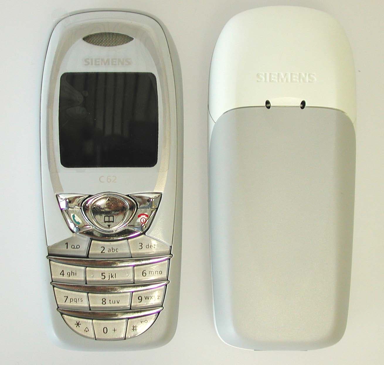
Click to zoom
Application Details
- Equipment Class
- PCE - PCS Licensed Transmitter held to ear
- Date of Grant
- Sep 30, 2003
- Application Purpose
- Original Equipment
- Date of Application
- Sep 30, 2003
- Equipment Note
- GSM / GPRS Mobile Phone
- Frequency Range
- 1850.20000000 - 1909.80000000
- Country
- Finland
Documents & Files
Document Text
Text extracted from the exhibit documents filed with the FCC. Open a document above to read the original.
Users Manual
Contents 1 This is a short version of User Guide. You can download the detailed version from the Internet at: www.my-siemens.com/c62 C62 am, A31008-H5700-A1-2-7619 (25. August 2003, 17:16) © Siemens AG 2003, I:\Mobil\L55\C62_Squirrel_(mc)\am\_for_fcc\C62_SquirrelTOC.fm Safety precautions ...................... 2 Safety Information ...................... 4 Antenna care ........................... 4 Phone operation ...................... 4 Electronic devices .................... 5 SAR (Cell Phone Designation) ..... 8 Phone overview ........................ 10 Display symbols (selection) ...... 12 Getting started.......................... 14 Insert SIM card/battery ........... 14 Charging the battery ............... 15 Switching on/off, PIN ................ 16 Switching on your phone for the first time ......................... 16 General information ................. 18 Security ..................................... 19 Codes .................................... 19 Clear SIM-card barring ............ 19 Making a phone call.................. 20 Handsfree ............................... 21 Hold call ................................. 22 Conference ............................. 22 Text entry.................................. 23 Addressbook ............................. 26 <New entry> .......................... 26 Call (search for an entry) ........ 27 Edit entry ............................... 27 Groups ................................... 27 Businesscard .......................... 28 SIM card entry ........................ 28 Records ..................................... 29 Durat/charges ........................ 29 Surf & fun .................................. 30 Internet browser (WAP) ..........30 Games ................................... 31 Organiser................................... 32 Calendar ................................ 32 Appointments .........................32 Voice mail/CB services ............... 34 SMS............................................ 35 MMS .......................................... 37 Message lists and profiles ......... 39 Profiles....................................... 40 Extras......................................... 41 SAT menu .............................. 41 Alarm clock ............................. 41 Calculator ............................... 41 Recorder ................................. 42 Stopwatch............................... 43 Countdown ........................... 43 Camera (Accessories) ..............43 Fast access................................. 45 Filesystem ................................. 46 Setup ......................................... 47 Data Exchange Software ...........53 Questions & Answers ................ 54 Customer Care ........................... 57 Menu tree .................................. 59 Product data .............................. 64 Care and maintenance .............. 65 U.S. FDA ..................................... 66 FCC/Industry Canada Notice ......72 Ten Driving Safety Tips.............. 73 Intellectual Property.................. 75 Battery quality statement ......... 76 Index.......................................... 77 Contents This is a short version of User Guide. You can download the detailed ver- sion from the Internet at: www.my-sie- mens.com/ c62 Safety precautions 2 C62 am, A31008-H5700-A1-2-7619 (15. September 2003, 16:20) © Siemens AG 2002, I:\Mobil\L55\C62_Squirrel_(mc)\am\_for_fcc\C62_SafetyInform.fm Safety precautions Information for parents Please read the operating instructions and safety precautions carefully before use. Explain the content and the hazards associated with using the phone to your children. Remember to comply with legal requirements and local restric- tions when using the phone. For example in aeroplanes, petrol stations, hospitals or while driving. Mobile phones can interfere with the functioning of medical devices such as hearing aids or pacemakers. Keep at least 20 cm/9 inches between phone and pacemaker. When using the mobile phone hold it to the ear which is further away from the pacemaker. For more infor- mation consult your doctor. The SIM card and MultiMediaCard may be removed. Caution! Small parts like this could be swallowed by young children. The mains voltage specified on the power supply unit (Volt) must not be exceeded. Other- wise the charging device may be destroyed. Acoustic Shock Warning The ringtone (page 48), info tones (page 48) and speaker- phone talking are reproduced through the loudspeaker. Do not hold the phone to the ear when it rings or when you have switched on the speakerphone function (page 21). Otherwise, there is a risk of serious lasting damage to hearing. Only use original Siemens bat- teries (100 % mercury-free) and – charging devices. Otherwise you risk serious damage to health and property. The battery could explode, for instance. You may only open the phone to replace the battery (100 % mer- cury-free), SIM card or MultiMediaCard. You must not open the battery under any circumstances. All other changes to this device are strictly prohibited and will invali- date the operating licence. Safety precautions 3 C62 am, A31008-H5700-A1-2-7619 (15. September 2003, 16:20) © Siemens AG 2002, I:\Mobil\L55\C62_Squirrel_(mc)\am\_for_fcc\C62_SafetyInform.fm Important: Please dispose of unwanted batteries and phones as permit- ted by the laws in your country. The phone may cause interfer- ence in the vicinity of TV sets, radios and PCs. Use only Siemens original accessories. This will avoid potential risks to health or prop- erty and ensure compliance with all relevant regulations. Improper use will invalidate the guarantee! Safety Information 4 C62 am, A31008-H5700-A1-2-7619 (15. September 2003, 16:20) © Siemens AG 2002, I:\Mobil\L55\C62_Squirrel_(mc)\am\_for_fcc\C62_SafetyInform.fm Safety Infor- mation Antenna care Use only the supplied or an approved replacement antenna. Unauthorized antennas, modifications, or attach- ments could damage the phone and may v…
Text truncated - open the document above for the full version.
Cover Letter(s)
25.9.2003 Subject: Request for Confidentiality FCC ID: RB9C62 To Whom It May Concern: In accordance with §0.459 of CFR 47, Microcell S.A. requests confidentiality for the following items 1. Block Diagram (Exhibit 4) 2. Schematic Diagram (Exhibit 5) 3. Part List (Exhibit 10) 4. Operational Description (Exhibit12). 5. Transmitter tune up procedure for C62.pdf These items contain detailed system and equipment description and related information about the product which Microcell S.A. considers to be proprietary, confidential and a custom design which otherwise would not be released to the general public. Since this design is a basis from which future technological products will evolve, Microcell S.A. also feels that this information would be of benefit to its competitors, and that the disclosure of the information in these exhibits would give our competitors an unfair advantage in the market. Best Regards, Jyrki Kortesalmi, On behalf of Microcell S.A.
External Photos
C62 External photographs of the equipment Photograph no.:1 Photograph no.:2 Photograph no.:3 Photograph no.:4 GSM triple-band antenna
ID Label/Location Info
Marking Drawing 1 (2) Prepared Subject respons. No. Harri Niemelä Doc.respons. / approved Check. Date Rev. File Approved / James Watson 30.August.2003 1.0 Title Siemens C62 STC62 std Phone label Marking Drawings with FFC ID The label template is based on the MC (30mm x 17mm). All text is Helvetica Bold font. (x,y) co-ordinates refer to the bottom left corner position. 1.1 Content Line A1: a: “Siemens” symbol b: “C62” c: “Made in Xxxx”-marking of origin. Line A2: Line Graphic Line B1: “Siemens Product Code” Line B2: a: “CE”-symbol b: “0889”-symbol c: “FCC ID: RB9C62”-text Line C1: Line C2 in bar code, (only actual number). Line C2: a: Electronic Serial Number (IMEI) of the included telephone; “XXXXXXXX-SSSSSS-C” b: “Warning”-symbol Line C3: Line D2 in bar code Line D1: a: Manufacturing Date; e.g “02W52” b: MC Custom Product Code of the included telephone; e.g: “08000000”. Line D2: Production Serial Number of the included telephone; e.g: “ZAL1234567”, ”NAN1234567”. Marking Drawing 2 (2) Prepared Subject respons. No. Harri Niemelä Doc.respons. / approved Check. Date Rev. File Approved / James Watson 30.August.2003 1.0 1.2 Format Line A1: a:(2,2.5) Graphics, height 2mm. b:(11,2.75) Text; height 2.6mm. c:(15,2.75) Text; height 1.5mm. Line A2: (2,3) Line; length 26mm, height 0.2mm Line B1: (11,5) Text; height 1.5mm. Line B2: a:(2,8.5) Graphics, height 5mm. b:(10,8.5) Graphics, height 3.5mm. b:(18,7) Text, height 1.5mm. Line C1: (2,11.75) Bar Code; height 3mm; narrow bar width (dots) 3 0.12mm, 18.45 (cpi) space correction 1 Code 128 symbology, Type Auto subset. Line C2: a:(2,13.5) Text; height 1.5mm. b:(24,14,5) Graphics, height 4mm. Line C3: (2,15.5) Bar Code; height 2mm; narrow bar width (dots) 2 0.08mm, 27.68 (cpi) space correction 1 Code 128 symbology, type Code A subset. Line D1: a:(16,16.5)Text; height 1.5mm. b:(22,16.5)Text; height 1.5mm. Line D2: (2,17) Text; height 1.5mm.
Internal Photos
C62 Internal photographs of the equipment Photograph no.:1 Photograph no.:2 Photograph no.:3 GSM antenna connector
Parts List/Tune Up Info
Detailed description of modulation system for C62 25.9.2003 Confidential Page 1 of 12 © Microcell Ltd. The contents of this document are confidential and must not be disclosed wholly or in part to any third party without the prior written consent of Microcell Ltd. Detailed description of modulation system for C62 Author Jari Greus Status Approved Version 1.0 Detailed description of modulation system for C62 25.9.2003 Confidential Page 2 of 12 © Microcell Ltd. MICROCELL Ltd, Kaarnatie 38, FIN-90530, OULU, FINLAND Change History Version Date Handled / Approved by Status More Information 1.0 25.09.2003 Jari Greus Approved Detailed description of modulation system for C62 25.9.2003 Confidential Page 3 of 12 © Microcell Ltd. TABLE OF CONTENTS Glossary ..........................................................................................................................4 1 DETAILED DESCRIPTION OF MODULATION SYSTEM........................................6 1.1 D5.1 GMSK Modulation ......................................................................................6 Detailed description of modulation system for C62 25.9.2003 Confidential Page 4 of 12 © Microcell Ltd. GLOSSARY Detailed description of modulation system for C62 25.9.2003 Confidential Page 5 of 12 © Microcell Ltd. Detailed description of modulation system for C62 25.9.2003 Confidential Page 6 of 12 © Microcell Ltd. 1 DETAILED DESCRIPTION OF MODULATION SYSTEM The following description of modulation system is taken directly from Appendix D Digital Modulation and GMSK –University of Hull 1.1 D5.1 GMSK Modulation There are two methods to generate GMSK, one is frequency shift keyed modulation, the other is quadrature phase shift keyed modulation. The implementation in the second employs a quadrature baseband process followed by a quadrature modulator. With this implementation, the modulation index can be maintained at exactly 0.5. This method is also cheaper to implement. Both methods lead to the same GMSK modulated signal. We are going to be looking at the second of these two methods, that is we shall be looking at a quadrature baseband processor followed by a quadrature modulator as Detailed description of modulation system for C62 25.9.2003 Confidential Page 7 of 12 © Microcell Ltd. shown in the second. The Gaussian low-pass filter has an impulse response given by the following equation Bb is the bandwidth of the low pass filter having a Gaussian shaped spectrum, T is the bit period and BN=B b T is the normalised bandwidth. To demonstrate this, we are looking at a filter with a bandwidth of B b =1000 and a bit rate of T=1/2000, i.e. a normalised bandwidth B N=Bb.T =0.5. The impulse response of the Gaussian low-pass filter has to be truncated and scaled, according to the B N value, to ensure that the effect of a single 1 passing through the filter, is a phases change of π/2. For a B N of 0.5 the filter response is truncated, symmetrically around zero, to two bit periods, i.e. from -T to T. The truncated filter response is represented graphically in the following figure. Detailed description of modulation system for C62 25.9.2003 Confidential Page 8 of 12 © Microcell Ltd. Detailed description of modulation system for C62 25.9.2003 Confidential Page 9 of 12 © Microcell Ltd. Detailed description of modulation system for C62 25.9.2003 Confidential Page 10 of 12 © Microcell Ltd. Detailed description of modulation system for C62 25.9.2003 Confidential Page 11 of 12 © Microcell Ltd. Detailed description of modulation system for C62 25.9.2003 Confidential Page 12 of 12 © Microcell Ltd.
Parts List/Tune Up Info
Means for determining and stabilizing frequency in C62 12-Jul-2001 Confidential Page 1 of 7 © Microcell Ltd. The contents of this document are confidential and must not be disclosed wholly or in part to any third party without the prior written consent of Microcell Ltd. Means for determining and stabilizing frequency in C62 Author Jari Greus Status Approved Version 1.0 Means for determining and stabilizing frequency in C62 12-Jul-2001 Confidential Page 2 of 7 © Microcell Ltd. MICROCELL Ltd, Kaarnatie 38, FIN-90530, OULU, FINLAND Change History Version Date Handled / Approved by Status More Information 1.0 25.09.2003 Jari Greus Approved Means for determining and stabilizing frequency in C62 12-Jul-2001 Confidential Page 3 of 7 © Microcell Ltd. TABLE OF CONTENTS Glossary ..........................................................................................................................4 1 MEANS FOR DETERMINING AND STABILIZING FREQUENCY, SUPPRESSION OF SPURIOUS RADIATION, LIMITING MODULATION, AND LIMITING POWER ......5 Means for determining and stabilizing frequency in C62 12-Jul-2001 Confidential Page 4 of 7 © Microcell Ltd. GLOSSARY Means for determining and stabilizing frequency in C62 12-Jul-2001 Confidential Page 5 of 7 © Microcell Ltd. 1 MEANS FOR DETERMINING AND STABILIZING FREQUENCY, SUPPRESSION OF SPURIOUS RADIATION, LIMITING MODULATION, AND LIMITING POWER As required by § 2.1033(c)(10), this exhibit details the methods employed to determine and stabilize frequency, suppress spurious radiation and to limit both modulation and power Means for Determining and Stabilizing Frequency The frequency stability of the equipment shall be sufficient to ensure that the fundamental emission stays within the authorized frequency block. Specifically, this is accomplished as follows: The transmit RF carrier of the Engine is generated by a voltage controlled oscillator (VCO) which is phase locked to a 13 MHz master reference clock. This 13 MHz source is synchronized to the GSM network and, within the engine board, is controlled by an 10 bit DAC to keep the carrier to within ±0.1 ppm of the network reference. As a GSM-compliant terminal, the stability of the engine board carrier is to be within ±0.1 ppm (±190 Hz in PCS 1900MHz) of the nominal value, in accordance with GSM performance requirements 3GPP TS 51.010 Means for Suppression of Spurious Radiation Suppression of spurious and harmonic radiation in the engine board is ensured through good engineering practices and proper transmitter design, layout, and construction. 1. Transmitter Architecture and Design −Frequency plan of the transmitter—local oscillator frequencies were selected to minimize spurious products. −Use of an direct conversion architecture to minimize spurious and noise power level in the PCS1900 receive band (1930-1990 MHz). −Lowpass filtering within and prior to the Antenna switch module to further reduce harmonics. 2. Physical realization of the engine −Fully shielded GSM radio module construction with filtering on all signal (data,control,clock) and power supply leads. −Localized shielding over the GSM radio and digital/baseband sections. −Careful component placement and layout, multi-layer circuit board construction,microstrip signal routing, and construction techniques to eliminate cavity moding and resonances. Means for determining and stabilizing frequency in C62 12-Jul-2001 Confidential Page 6 of 7 © Microcell Ltd. Means for Limiting Modulation Per GSM specifications, the modulation scheme implemented by the engine board is Gaussian MSK (GMSK), with a bandwidth-time product of BT = 0.3. Modulation rate is 1625/6 kbps, or approximately 280.83 kbps. To minimize spreading of the spectrum, GSM standards require that the RF output spectrum meet the mask shown in Figure E6.1. In the engine board, modulation accuracy is maintained through the use of direct digital synthesis techniques. Figure E6.1. GSM terminal modulation mask. Means for Limiting Power As a GSM-compliant terminal, the engine board is capable of transmitting at any of the 16 defined nominal RF output power levels, ranging from 30.0 dBm to 0.0 dBm, during its assigned TDMA frame. Engine board transmitter operation (output power level) is controlled by the GSM network, and specifically by the base station to which the engine board is attached. All RF output power levels of the engine board are set at the factory and cannot be altered or increased by user. Furthermore, the temporal variation in power level within each transmission (i.e., transmission burst time mask) is in accordance with GSM requirements. This is accomplished by adjusting transmitter gain through a power control loop and ramping the transmitter on and off at the beginning and ending of each burst. The power control loop is integrated to Power Amplifier Module proven to have little effect on output power versus temperature. Maximum RF power is adjusted to within the specified tolerance during each burst, at the output power level specified by the base station. Means for determining and stabilizing frequency in C62 12-Jul-2001 Confidential Page 7 of 7 © Microcell Ltd.
RF Exposure Info
Radio Frequency Investigation Ltd, Ewhurst Park, Ramsdell, Basingstoke, Hampshire, RG26 5RQ, ENGLAND. Tel: +44 (0) 1256 851193 Fax: +44 (0) 1256 851192 Registered in England, No. 211 7901. Registered Office: Ewhurst Park, Ramsdell, Basingstoke, Hampshire RG26 5RQ TEST REPORT FROM RADIO FREQUENCY INVESTIGATION LTD. Test Of: Microcell Ltd. C62 Mobile Telephone Handset with Camera, Headset PTT and Case Accessories To: OET Bulletin 65 Supplement C: (2001-01) Test Report Serial No: RFI/SARB2/RP45006JD14A Supersedes Test Report Serial No: RFI/SARB1/RP45006JD14A Measurements were performed on the DASY4 System This Test Report Is Issued Under The Authority Of Richard Jacklin, Operations Director: Checked By: Tested By: Release Version No: PDF01 Issue Date: 24 September 2003 Test Dates: 27 August 2003 to 03 September 2003 It should be noted that the standard, OET Bulletin 65 Supplement C: (2001-01) is not listed on RFIs current UKAS schedule and is therefore “not UKAS accredited”. This report is issued in Adobe Acrobat portable document format (PDF). It is only a valid copy of the report if it is being viewed in PDF format with the following security options not allowed: Changing the document, Selecting text and graphics, Adding or changing notes and form fields. Furthermore, the date of creation must match the issue date stated above. This report may be copied in full. The results in this report apply only to the sample(s) tested. RADIO FREQUENCY INVESTIGATION LTD. TEST REPORT S.No. RFI/SARB2/RP45006JD14A Operations Department Page 2 of 38 Issue Date: 24 September 2003 Test Of: Microcell Ltd. C62 Mobile Telephone Handset To: OET Bulletin 65 Supplement C: (2001-01) This page has been left intentionally blank. RADIO FREQUENCY INVESTIGATION LTD. TEST REPORT S.No. RFI/SARB2/RP45006JD14A Operations Department Page 3 of 38 Issue Date: 24 September 2003 Test Of: Microcell Ltd. C62 Mobile Telephone Handset To: OET Bulletin 65 Supplement C: (2001-01) Table of Contents 1. Client Information..........................................................................................................4 2. Equipment Under Test (EUT) .......................................................................................5 3. Test Specification, Methods And Procedures ..........................................................10 4. Deviations From The Test Specification ...................................................................11 5. Operation Of The EUT During Testing ......................................................................12 6. Summary Of Test Results...........................................................................................13 7. SAR Measurement System.........................................................................................18 8. SAR Safety Limits .......................................................................................................19 9. Details of SAR Evaluation ..........................................................................................20 10. Evaluation Procedures .............................................................................................21 11. System Validation .....................................................................................................22 12. Simulated Tissues.....................................................................................................23 13. Tissue Parameters ....................................................................................................24 14. DASY4 Systems Specifications ...............................................................................25 15. Validation Results –1900 MHz Head (01 September 2003) ....................................26 16. Validation Results –1900 MHz Head/Body (02 September 2003) ..........................27 17. Validation Results –1900 MHz Head/Body (03 September 2003) ..........................28 18. Measurement Uncertainty ........................................................................................29 Appendix 1. Test Equipment Used ................................................................................31 Appendix 2. SAR Distribution Scans.............................................................................32 Appendix 3. Test Configuration Photographs..............................................................33 Appendix 4. Calibration Data .........................................................................................35 Appendix 5. Photographs of EUT ..................................................................................37 Test Report Serial No: RFI/SARB2/RP45006JD14A Supersedes Test Report Serial No: RFI/SARB1/RP45006JD14A RADIO FREQUENCY INVESTIGATION LTD. TEST REPORT S.No. RFI/SARB2/RP45006JD14A Operations Department Page 4 of 38 Issue Date: 24 September 2003 Test Of: Microcell Ltd. C62 Mobile Telephone Handset To: OET Bulletin 65 Supplement C: (2001-01) 1. Client Information 1.1. Client Details Company Name: Microcell Ltd. Address: Kaarnatie 38 Oulu FIN-90530 Finland Contact Name: Mr Kortesalmi 1.2. Test Laboratory Company Name: Radio Frequency Investigation Ltd. Address: Ewhurst Park Ramsdell Basingstoke Hampshire RG26 5RQ. Contact Name: Mr J Lomako RADIO FREQUENCY INVESTIGATION LTD. TEST REPORT S.No. RFI/SARB2/RP45006JD14A Operations Department Page 5 of 38 Issue Date: 24 September 2003 Test Of: Microcell Ltd. C62 Mobile Telephone Handset To: OET Bulletin 65 Supplement C: (2001-01) 2. Equipment Under Test (EUT) The following information (with the exception of the Date of Receipt) has been supplied by the client: 2.1. Identification Of Equipment Under Test (EUT) Brand Name Siemens Model Name or Number C62 FCC Identification RB9C62 IMEI Number 004400-00-38979151-4849 Battery Serial Number 006071 16EMCSY / 006110 16EMCSY Country Of Manufacture None stated Date Of Receipt 27 August 2003 Brand Name Siemens Model Name or Number QuickPic Camera 1QP-500 FCC Iden…
Text truncated - open the document above for the full version.
RF Exposure Info
Radio Frequency Investigation Ltd, Ewhurst Park, Ramsdell, Basingstoke, Hampshire, RG26 5RQ, ENGLAND. Tel: +44 (0) 1256 851193 Fax: +44 (0) 1256 851192 Registered in England, No. 211 7901. Registered Office: Ewhurst Park, Ramsdell, Basingstoke, Hampshire RG26 5RQ SAR CALIBRATION DATA Test Of: Microcell Ltd. C62 Mobile Telephone Handset with Camera, Headset PTT and Case Accessories To: OET Bulletin 65 Supplement C: (2001-01) Test Report Serial No.: RFI/EMCB1/45006_Calibration Data RADIO FREQUENCY INVESTIGATION LTD. TEST REPORT Calibration Data Operations Department RFI/EMCB1/45006_Calibration Data Test Of: Microcell Ltd. C62 Mobile Telephone Handset To: OET Bulletin 65 Supplement C: (2001-01) SAR Calibration Data This document contains the calibration data relating to RFI test report Serial No.: RFI/EMCB1/RP45006JD14A
RF Exposure Info
Radio Frequency Investigation Ltd, Ewhurst Park, Ramsdell, Basingstoke, Hampshire, RG26 5RQ, ENGLAND. Tel: +44 (0) 1256 851193 Fax: +44 (0) 1256 851192 Registered in England, No. 211 7901. Registered Office: Ewhurst Park, Ramsdell, Basingstoke, Hampshire RG26 5RQ SAR DISTRIBUTION SCANS Test Of: Microcell Ltd. C62 Mobile Telephone Handset with Camera, Headset PTT and Case Accessories To: OET Bulletin 65 Supplement C: (2001-01) Test Report Serial No.: RFI/EMCB1/45006_Distribution Scans RADIO FREQUENCY INVESTIGATION LTD. TEST REPORT Distribution Scans Operations Department RFI/EMCB1/45006_Distribution Scans Test Of: Microcell Ltd. C62 Mobile Telephone Handset To: OET Bulletin 65 Supplement C: (2001-01) SAR Distribution Scans This document contains the SAR Distribution scans relating to RFI test report Serial No.: RFI/EMCB1/RP45006JD14A Page 1 of 2 file://C:\Documents and Settings\Administrator...\System Performance Check-D1900 1 09 03-3.ht23/09/2003 Date: 01/09/03 Test Laboratory: RADIO FREQUENCY INVESTIGATION LTD. DUT: Dipole 1900 MHz; Type: D1900V2; Serial: SN540 Communication System: CW; Frequency: 1900 MHz;Duty Cycle: 1:1 Medium: 1900MHz HSL (σ = 1.45904 mho/m, ε r = 38.0259, ρ = 1000 kg/m 3 ) Phantom section: Flat Section DASY4 Configuration: - Probe: ET3DV6 - SN1528; ConvF(4.8, 4.8, 4.8); Calibrated: 29/07/2003 - Sensor-Surface: 4mm (Mechanical Surface Detection) Sensor-Surface: 4mm (Mechanical And Optical Surface Detection) - Electronics: DAE3 Sn450; Calibrated: 19/05/2003 - Phantom: SAM 12b; Type: SAM 4.0; Serial: TP:1197 - Measurement SW: DASY4, V4.1 Build 47; Postprocessing SW: SEMCAD, V1.6 Build 116 d=10mm, Pin=250mW/Area Scan (51x51x1): Measurement grid: dx=20mm, dy=20mm Reference Value = 93.3 V/m 0 dB = 11.6mW/g Page 2 of 2 file://C:\Documents and Settings\Administrator...\System Performance Check-D1900 1 09 03-3.ht23/09/2003 Power Drift = 0.04 dB Maximum value of SAR = 12.6 mW/g d=10mm, Pin=250mW/Zoom Scan 7x7x7 (7x7x7)/Cube 0: Measurement grid: dx=5mm, dy=5mm, dz=5mm Peak SAR (extrapolated) = 17.4 W/kg SAR(1 g) = 10.3 mW/g; SAR(10 g) = 5.36 mW/g Reference Value = 93.3 V/m Power Drift = 0.04 dB Maximum value of SAR = 11.6 mW/g Page 1 of 2 file://C:\Documents and Settings\Administ...\45006JD14 1900 OET LHS_RETEST_1 09 03-5.ht23/09/2003 Date: 01/09/03 Test Laboratory: RADIO FREQUENCY INVESTIGATION LTD. DUT: C62; Type: SQU3000015; Serial: 004400-00-389791-51-4849 Communication System: DCS 1900; Frequency: 1879.8 MHz;Duty Cycle: 1:8.3 Medium: 1900MHz HSL (σ = 1.43769 mho/m, ε r = 38.1093, ρ = 1000 kg/m 3 ) Phantom section: Left Section DASY4 Configuration: - Probe: ET3DV6 - SN1528; ConvF(4.8, 4.8, 4.8); Calibrated: 29/07/2003 - Sensor-Surface: 4mm (Mechanical Surface Detection) - Electronics: DAE3 Sn450; Calibrated: 19/05/2003 - Phantom: SAM 12b; Type: SAM 4.0; Serial: TP:1197 - Measurement SW: DASY4, V4.1 Build 47; Postprocessing SW: SEMCAD, V1.6 Build 116 Touch position - Middle/Area Scan 2 (101x121x1): Measurement grid: dx=15mm, dy=15mm Reference Value = 14.2 V/m Power Drift = -0.02 dB 0 dB = 0.271mW/g Page 2 of 2 file://C:\Documents and Settings\Administ...\45006JD14 1900 OET LHS_RETEST_1 09 03-5.ht23/09/2003 Maximum value of SAR = 0.358 mW/g Touch position - Middle/Zoom Scan (7x7x7) (7x7x7)/Cube 0: Measurement grid: dx=5mm, dy=5mm, dz=5mm Peak SAR (extrapolated) = 0.474 W/kg SAR(1 g) = 0.316 mW/g; SAR(10 g) = 0.177 mW/g Reference Value = 14.2 V/m Power Drift = -0.02 dB Maximum value of SAR = 0.347 mW/g Touch position - Middle/Zoom Scan (7x7x7) (7x7x7)/Cube 1: Measurement grid: dx=5mm, dy=5mm, dz=5mm Peak SAR (extrapolated) = 0.388 W/kg SAR(1 g) = 0.246 mW/g; SAR(10 g) = 0.141 mW/g Reference Value = 14.2 V/m Power Drift = -0.02 dB Maximum value of SAR = 0.271 mW/g Page 1 of 2 file://C:\Documents and Settings\Adminis...\45006JD14 1900 OET RHS_RETEST_1 09 03-13.ht23/09/2003 Date: 01/09/03 Test Laboratory: RADIO FREQUENCY INVESTIGATION LTD. DUT: C62; Type: SQU3000015; Serial: 004400-00-389791-51-4849 Communication System: DCS 1900; Frequency: 1909.8 MHz;Duty Cycle: 1:8.3 Medium: 1900MHz HSL (σ = 1.45904 mho/m, ε r = 38.1259, ρ = 1000 kg/m 3 ) Phantom section: Right Section DASY4 Configuration: - Probe: ET3DV6 - SN1528; ConvF(4.8, 4.8, 4.8); Calibrated: 29/07/2003 - Sensor-Surface: 4mm (Mechanical Surface Detection) - Electronics: DAE3 Sn450; Calibrated: 19/05/2003 - Phantom: SAM 12b; Type: SAM 4.0; Serial: TP:1197 - Measurement SW: DASY4, V4.1 Build 47; Postprocessing SW: SEMCAD, V1.6 Build 116 Worst-case - High - Tilt RHS/Area Scan 2 (131x141x1): Measurement grid: dx=15mm, dy=15mm Reference Value = 11.5 V/m Power Drift = 0.06 dB 0 dB = 0.254mW/g Page 2 of 2 file://C:\Documents and Settings\Adminis...\45006JD14 1900 OET RHS_RETEST_1 09 03-13.ht23/09/2003 Maximum value of SAR = 0.249 mW/g Worst-case - High - Tilt RHS/Zoom Scan (7x7x7) (7x7x7)/Cube 0: Measurement grid: dx=5mm, dy=5mm, dz=5mm Peak SAR (extrapolated) = 0.417 W/kg SAR(1 g) = 0.231 mW/g; SAR(10 g) = 0.119 mW/g Reference Value = 11.5 V/m Power Drift = 0.06 dB Maximum value of SAR = 0.254 mW/g Page 1 of 2 file://C:\Documents and Settings\Adminis...\45006JD14 1900 OET RHS_RETEST_1 09 03-11.ht23/09/2003 Date: 01/09/03 Test Laboratory: RADIO FREQUENCY INVESTIGATION LTD. DUT: C62; Type: SQU3000015; Serial: 004400-00-389791-51-4849 Communicat…
Text truncated - open the document above for the full version.
Contact Information
Applicant
Mikko Laamanen
Technical Contact
Test Firm
RFI Global Services Ltd.Allan Hume
Technical Specifications
| # | Rule Parts | Frequency Range | Power Output | Emission | Tolerance |
|---|---|---|---|---|---|
| 1 | 24E | 1.85 GHz - 1.91 GHz | 1.95 W | 249KGXW | 0.1000000000 ppm |
Other Applications from Microcell SA, Lux., Swiss Branch
RB90601
Dec 18, 2003Licensed Transmitter
Equipment Class
PCE - PCS Licensed Transmitter held to ear