RBPPJ1000Wireless Receipt Printer
TransAct Technologies Incorporated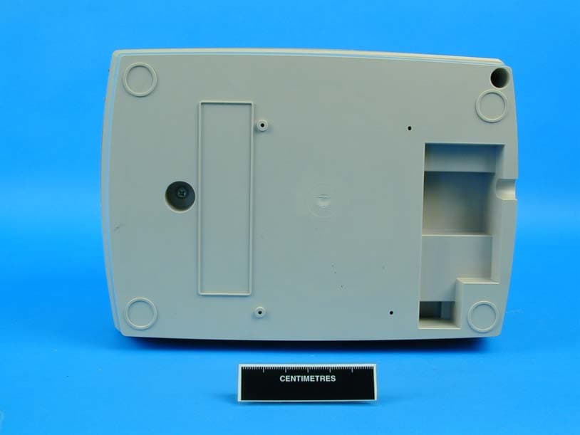
Click to zoom
Application Details
- Equipment Class
- DSS - Part 15 Spread Spectrum Transmitter
- Date of Grant
- Sep 29, 2003
- Application Purpose
- Original Equipment
- Date of Application
- Sep 29, 2003
- Equipment Note
- Wireless Receipt Printer
- Frequency Range
- 2412.00000000 - 2462.00000000
- Country
- United States
Documents & Files
Document Text
Text extracted from the exhibit documents filed with the FCC. Open a document above to read the original.
Users Manual
Your POSjet 1000 printer has been equipped with an 802.11b compatible wireless interface. Before it can be used, this unit must be properly installed and configured. Installation: The printer must be located within range of a compatible access point.. Dsitance from the access point, intervening walls, and local interference may, affect the operating range of the printer. If communcation to the printer cannot be successfully established , the printer and/or the access point may be relocated to correct the problem. Important! This product emits RF energy and must be located such a that a separation distance of at least 20cm is maintained between the printer and the body of the user or nearby personnel. Any modifications or changes made to the printer without the express approval of TransAct Technologies Incorporated may void the user’s authority to operate the device. Configuration: The printer is shipped with a default configuration installed in the wireless adapter. Before the product can be used, the unit must be reconfigured to match the parameters of the desired wireless network. The current printer configuration can be obtained by placing the printer in self test mode as described in the “Testing the Printer/Verifying Printer Settings” of the iTherm 280 Quick Reference sheet. The printout will include the currently configured wireless communicaitons parameters. Changing the wireless configuration requires the use of the TransAct Wireless Configuration Utility, Part Number 100- 04637. This utility, along with configuration instructions, is available on the TransAct Wireless Configuration CD, Part Number 100-04636 and is also available for download at www.transact-tech.com TransAct Technologies Inc. Ithaca Facility 20 Bomax Drive Ithaca, NY 14850 USA Telephone(877) 748-4222 or (607) 257-8901 Main Fax(607) 257-8922 Sales Fax:(607) 257-3868 Tech. Support Fax:(607) 257-3911 Web site:http://www.transact-tech.com 100-04639 REV A 9/03 Quick ReferenceQuick Reference Wireless InterfaceWireless Interface POSPOSjet 1000 ®
Cover Letter(s)
Symbol Technologies, Inc. 1 May 2003 TransAct Technologies Incorporated Attn: Donald Brooks 20 Bomax Drive Ithaca, NY 14850 RE: Authorization for TransAct Technologies Incorporated to apply for Regulatory Approvals for TransAct Technologies Incorporated products that include the Symbol Technologies Inc. radio card Model number CC-4137-1000-WW. Dear Mr. Brooks, This letter grants authorization for TransAct Technologies Incorporated to apply for Regulatory Approvals for TransAct Technologies Incorporated products that include the Symbol Technologies Inc. radio card: Model number CC-4137-1000-WW This letter grants authorization for TransAct Technologies Incorporated to apply to the Federal Communications Commission, Industry Canada, and other International Regulatory Agencies for a Grant under TransAct Technologies Incorporated’s Grantee Code or the equivalent, for TransAct Technologies Incorporated products that include the Symbol Technologies Inc. radio card: Model number CC-4137-1000-WW This letter grants authorization for TransAct Technologies Incorporated to pursue Test Reports that are for the single purpose of gaining International Regulatory Approvals for TransAct Technologies Incorporated products that include the Symbol Technologies Inc. radio card: Model number CC-4137-1000-WW No other changes or modifications are authorized; all of Symbol Technologies Inc. Regulatory Approvals for the radio card Model number CC-4137-1000-WW are to remain in effect and on file. This letter of authorization to remain in effect until notified or 3 years, which ever comes first. Respectfully Marks S. Luksich Director, Regulatory Symbol Technologies Inc. SYMBOL TECHNOLOGIES INC. One Symbol Plaza . (561) 487-1718 . Fax (561) 483-3922
External Photos
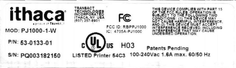
TransAct FCC ID:RBPPJ1000 External photos TransAct FCC ID:RBPPJ1000 External photos TransAct FCC ID:RBPPJ1000 External photos TransAct FCC ID:RBPPJ1000 External photos
Internal Photos
© 2001 PCTEST Lab SYMBOL FCC ID: H9PLA4137 NVLAP Lab Code: 100431-0 DSSS Radio Card (PCMCIA) © 2001 PCTEST Lab SYMBOL FCC ID: H9PLA4137 NVLAP Lab Code: 100431-0 DSSS Radio Card (PCMCIA) © 2001 PCTEST Lab SYMBOL FCC ID: H9PLA4137 NVLAP Lab Code: 100431-0 DSSS Radio Card (PCMCIA) © 2001 PCTEST Lab SYMBOL FCC ID: H9PLA4137 NVLAP Lab Code: 100431-0 DSSS Radio Card (PCMCIA) © 2001 PCTEST Lab SYMBOL FCC ID: H9PLA4137 NVLAP Lab Code: 100431-0 DSSS Radio Card (PCMCIA) © 2001 PCTEST Lab SYMBOL FCC ID: H9PLA4137 NVLAP Lab Code: 100431-0 DSSS Radio Card (PCMCIA) © 2001 PCTEST Lab SYMBOL FCC ID: H9PLA4137 NVLAP Lab Code: 100431-0 DSSS Radio Card (PCMCIA)
Internal Photos
TransAct FCC ID:RBPPJ1000 Internal photos TransAct FCC ID:RBPPJ1000 Internal photos TransAct FCC ID:RBPPJ1000 Internal photos TransAct FCC ID:RBPPJ1000 Internal photos TransAct FCC ID:RBPPJ1000 Internal photos TransAct FCC ID:RBPPJ1000 Internal photos TransAct FCC ID:RBPPJ1000 Internal photos
Operational Description
1 of 10 SPECIFICATIONS AND APPLICATION NOTES January 29, 2001 MicroBlue TM 2.4 2.4 GHz Microsphere Technology 2 of 10 Contents Technology . . . . . . . . . . . . . . . . . . . . . . . . . . . . . . . . . . . . . . . . . . . . . . . . . 3 Physical Dimensions . . . . . . . . . . . . . . . . . . . . . . . . . . . . . . . . . . . . . . . . . . 4 Electrical Performance. . . . . . . . . . . . . . . . . . . . . . . . . . . . . . . . . . . . . . . . . 5 Customize Antenna. . . . . . . . . . . . . . . . . . . . . . . . . . . . . . . . . . . . . . . . . . . .9 Contact Information. . . . . . . . . . . . . . . . . . . . . . . . . . . . . . . . . . . . . . . . . . . .10 Specifications Subject to Change Without Notice The information contained in this document and product are of a proprietary nature. They may not be reproduced without express written permission of Centurion Wireless Technologies, Inc. Lincoln, Nebraska. 3 of 10 Technology The MicroBlue 2.4 Microsphere Antenna is a versatile and easy to use antenna for the 2.4 to 2.5 GHz frequency band used by Bluetooth and IEEE 802.11 devices. Designed for easy connection to radio cards, it can be successfully used in many different applications. MicroBlue 2.4 shown here with standard 8 inches of RG-178 coax and right angle MMCX connector The antenna utilizes Centurion’s patented PCB Microsphere technology. It is designed to be fed by a 50-ohm coaxial cable terminated by an RF coaxial connector. This antenna has a ground plane incorporated into the resonator structure, therefore no additional ground plane is required to radiate efficiently. However, the configuration of the device in which the MicroBlue antenna is installed can have an impact on electrical performance (VSWR and gain). The polarization and radiation patterns can also be affected by placement of the antenna and geometry of the device. Contact Centurion Wireless for engineering assistance with your custom application. Specifications Subject to Change Without Notice The information contained in this document and product are of a proprietary nature. They may not be reproduced without express written permission of Centurion Wireless Technologies, Inc. Lincoln, Nebraska. 4 of 10 Physical Dimensions Standard Product Specifications: Part Number: CAF94131 MicroBlue Size: .89” x 1.88” x .032” (w x l x t) Standard Cable: RG-178 (MIL-C17) Coaxial Cable x 8” Long Standard Connector: Right-Angle MMCX Plug Specifications Subject to Change Without Notice The information contained in this document and product are of a proprietary nature. They may not be reproduced without express written permission of Centurion Wireless Technologies, Inc. Lincoln, Nebraska. 5 of 10 Electrical Performance • VSWR < 1.8:1 from 2.4 GHz to 2.5 GHz • 2:1 VSWR Bandwidth > 600 MHz • Peak Gain (Elev. Phi=0) > 0.5 dBi, Average Gain (Elev. Phi=0) > -3 dBi • Peak Gain (Elev. Phi=90) > 1.5 dBi, Average Gain (Elev. Phi=90) > -2.5 dBi • Peak Gain (Azimuth) > 1 dBi, Average Gain (Azimuth) > 0 dBi (All Electrical data based on standard product tested in free space) CH1 S 11 SWR1 /REF 1 START 2 000.000 000 MHzSTOP 3 000.000 000 MHz Cor PRm 9 Jan 2002 15:28:00 1 2 3 2_: 1.6135 2 450.000 000 MHz 1_: 1.6325 2.4 GHz 3_: 1.5778 2.5 GHz VSWR Pattern from 2000 to 3000 MHz Specifications Subject to Change Without Notice The information contained in this document and product are of a proprietary nature. They may not be reproduced without express written permission of Centurion Wireless Technologies, Inc. Lincoln, Nebraska. 6 of 10 Elevation Plane, Phi = 0, Gain Pattern at 2450 MHz Specifications Subject to Change Without Notice The information contained in this document and product are of a proprietary nature. They may not be reproduced without express written permission of Centurion Wireless Technologies, Inc. Lincoln, Nebraska. 7 of 10 Elevation Plane, Phi = 90, Gain Pattern at 2450 MHz Specifications Subject to Change Without Notice The information contained in this document and product are of a proprietary nature. They may not be reproduced without express written permission of Centurion Wireless Technologies, Inc. Lincoln, Nebraska. 8 of 10 Azimuth Plane, Gain Pattern at 2450 MHz Specifications Subject to Change Without Notice The information contained in this document and product are of a proprietary nature. They may not be reproduced without express written permission of Centurion Wireless Technologies, Inc. Lincoln, Nebraska. 9 of 10 Customize Antenna The intent of this design is for reference only so that Centurion’s customers can test and gage the performance of Centurion’s 2.4-2.5 GHz Microsphere Antenna. In order for the antenna system to perform at its maximum RF potential, Centurion recommends that the antenna solution be optimized per each application. In some cases, the antenna will require some re-tuning and can be fit in a slightly different form factor than shown in the standard product above. In many applications, the return loss (VSWR) performance will be such that no tuning or matching will be required. However, if you find that the cable length is too long, doesn’t have the right connector, or doesn’t quite tune or fit in your particular application. Please contact Centurion Wireless Technologies for engineering assistance with your custom application. Specifications Subject to Change Without Notice The information contained in this document and product are of a proprietary nature. They may not be reproduced without express written permission of Centurion Wireless Technologies, Inc. Lincoln, Nebraska. 10 of 10 Contact Information Centurion Wireless Technologies, Inc. Corporate Headquarters PO Box 82846 Lincoln, NE 68501 USA 402-474-0706 phone 402-467-4528 fax [email protected] www.centurion.com Centurion Wireless Technologies, Inc. 6252 West 91 st Avenue Westminster, CO 80031 USA 303-635-2000 phone 303-635-2003 fax Other Centurion Facilities: Aylesbury, U.K. 44-1296-339-808 phone 44-1296-489-949 fax Shanghai, P.R.C. 86-21…
Text truncated - open the document above for the full version.
Operational Description
Features: Versatile and easy to use antenna for 2.4 to 2.5 GHz Bluetooth and IEEE 802.11 devices Designed for easy connection to radio cards Utilizes Centurion’s patented PCB Microsphere technology Has a ground plane incorporated into the resonator structure, therefore no additional ground plane is required to radiate efficiently Specifications: Frequency Range 2.4 – 2.5 GHz Polarization Linear Peak Gain 1.5 dBi Average Gain >0 dBi Nominal Impedance 50 ohms VSWR (Min. Performance) < 1.8:1 from 2.4 GHz to 2.5 GHz 2:1 VSWR Bandwidth > 600 MHz Temperature Range -40° to +85°C Vibration 6G RMS (9.04g2/Hz) for 15 minutes each in vertical and horizontal. No appearance or functional axis. Thermal Shock Change after 4 repeated cycles of 1 hr. at +85°C and 1 hr. at -40°C. Transfer time is 5 min. Size (inches) .89” x 1.88” x .032” (w x l x t) Standard Cable RG-178 (MIL-C17) Coaxial Cable x 8” Long Standard Connector Right-Angle MMCX Plug MicroBlue Part Number (P/N): CAF94131 MicroBlue – 10/28/02 Elevation Plane Phi = 0, Gain Pattern at 2450 MHz Elevation Plane Phi = 90, Gain Pattern at 2450 MHz Azimuth Plane Gain Pattern at 2450 MHz MicroBlue 2.4 shown here with standard 8 inches of RG-178 coax and right angle MMCX connector
Test Report
FCC ID : H 9 P L A 4137 W L AN P C Card, 1 1 Mbps, T rilogy 3 CC-4137-1000-WW Antennas Ant No M o del S y m bo l P / N Ga i n (d Bi ) Ca b e l Lo ss (dB ) Pou t (d Bm ) Distance (m ) D e vi ce T y p e Ty pe En d C a p " C " 10-2 0 5 11- 01 0.0 0 .00 16.76 150 . 0 L a p top F- E l em e n t
Test Report
© 2001 PCTEST Engineering Lab., Inc. PCTEST Engineering Laboratory, Inc. 6660-B Dobbin Road • Columbia, MD 21045 • U.S.A. TEL (410) 290-6652 • FAX (410) 290-6654 http://www.pctestlab.com CERTIFICATE OF COMPLIANCE Symbol Technologies Inc. Dates of Tests: December 5, 2001 1 Symbol Plaza Test Report S/N: 15.211127701.H9P Holtsville, NY 11742-1300 Test Site: PCTEST Lab, Columbia MD U.S.A. Attn: Mark Luksich, Regulatory Engineer FCC ID H9PLA4137 APPLICANT SYMBOL TECHNOLOGIES INC. FCC Rule Part(s): § 15.247; ANSI C-63.4 (1992) Classification: Spread Spectrum Transceiver (DSS) Method/System: Direct Sequence Spread Spectrum System (DSSS) Equipment Type: DSSS Radio Card (PCMCIA) Max Radiated Power: 0.02 Watts (13.07 dBm) Frequency Range: 2412 — 2462 MHz Trade/Model No(s).: SYMBOL / CC-4137-1000-WW This equipment has been shown to be capable of compliance with the applicable technical standards as indicated in the measurement report and was tested in accordance with the measurement procedures specified in ANSI C-63-4. I attest to the accuracy of data. All measurements reported herein were performed by me or were made under my supervision and are correct to the best of my knowledge and belief. I assume full responsibility for the completeness of these measurements and vouch for the qualifications of all persons taking them. PCTEST certifies that no party to this application has been denied the FCC benefits pursuant to Section 5301 of the Anti-Drug Abuse Act of 1988, 21 U.S.C. 862. 211127702.H9P Test Report S/N: 15.211127701.H9P FCC Part 15.247 Dates of Tests: December 5, 2001 Certification © 2001 PCTEST Engineering Laboratory, Inc. FCC Part 15.247 TABLE OF CONTENTS SCOPE 1 INTRODUCTION (SITE DESCRIPTION) 2 PRODUCT INFORMATION 3 DESCRIPTION OF TESTS A. CONDUCTED EMISSIONS 4 B. RADIATED EMISSIONS 5 C. RESTRICTED BANDS 6 D. ANTENNA REQUIREMENT 7 E. DIRECT SEQUENCE BANDWIDTH 8 F. MAXIMUM PEAK POWER OUTPUT 9 G. POWER DENSITY 10 RADIATED MEASUREMENTS (FUNDAMENTAL & HARMONICS) 11 LIST OF TEST EQUIPMENT 12 CONCLUSION 13 ATTACHMENT A - TEST PLOTS ATTACHMENT B - FCC ID LABEL & LOCATION ATTACHMENT C - EXTERNAL PHOTOGRAPHS ATTACHMENT D - INTERNAL PHOTOGRAPHS ATTACHMENT E - TEST SETUP PHOTOGRAPHS ATTACHMENT F - SAR MEASUREMENT REPORT ATTACHMENT G - SAR TEST DATA ATTACHMENT H - SAR TEST SETUP PHOTOGRAPHS ATTACHMENT I - DIPOLE VALIDATION PLOTS ATTACHMENT J - PROBE CALIBRATION DATA Test Report S/N: 15.211127701.H9P FCC Part 15.247 Dates of Tests: December 5, 2001 Certification © 2001 PCTEST Lab SYMBOL FCC ID: H9PLA4137 1 DSSS RADIO CARD (PCMCIA) MEASUREMENT REPORT Scope - Measurement and determination of electromagnetic emissions (EME) of radio frequency devices including intentional and/or unintentional radiators for compliance with the technical rules and regulations of the Federal Communications Commission. §2.983(a) General Information Applicant Name: SYMBOL TECHNOLOGIES INC. Address: 1 Symbol Plaza Holtsville, NY 11742-1300 Attention: Mark Luksich, Regulatory Engineer • FCC ID: H9PLA4137 • Class: Spread Spectrum Transceiver (DSS) • Type: DSSS Radio Card (PCMCIA) • Freq. Range: 2412 — 2462 MHz • Method/System: Direct Sequence Spread Spectrum System (DSSS) • Model No(s): CC-4137-1000-WW • Max. RF Output Power: 0.02 Watts (13.07 dBm) • Rule Part(s): § 15.247 • Dates of Tests: December 5, 2001 • Place of Tests: PCTEST Lab, Columbia, MD U.S.A. • Test Report S/N: 15.211127701.H9P Test Report S/N: 15.211127701.H9P FCC Part 15.247 Dates of Tests: December 5, 2001 Certification © 2001 PCTEST Lab SYMBOL FCC ID: H9PLA4137 2 DSSS RADIO CARD (PCMCIA) INTRODUCTION The measurement procedure described in American National Standard for Methods of Measurement of Radio-Noise Emissions from Low-Voltage Electrical and Electronic Equipment in the Range of 9kHz to 40GHz (ANSI C63.4-1992) and FCC Public Notice dated July 12, 1995 entitled “Guidance on Measurement for Direct Sequence Spread Spectrum Systems” were used in the measurement of SYMBOL DSSS Radio Card (PCMCIA). These measurement tests were conducted at PCTEST Engineering Laboratory, Inc. facility in New Concept Business Park, Guilford Industrial Park, Columbia, Maryland. The site address is 6660-B Dobbin Road, Columbia, MD 21045. The test site is one of the highest points in the Columbia area with an elevation of 390 feet above mean sea level. The site coordinates are 39° 11'15" N latitude and 76° 49'38" W longitude. The facility is 1.5 miles North of the FCC laboratory, and the ambient signal and ambient signal strength are approximately equal to those of the FCC laboratory. There are no FM or TV transmitters within 15 miles of the site. The detailed description of the measurement facility was found to be in compliance with the requirements of § 2.948 according to ANSI C63.4 on October 19, 1992. PCTEST Location The map at right shows the location of the PCTEST Lab, its proximity to the FCC Lab, the Columbia vicinity area, the Baltimore-Washington International (BWI) airport, and the city of Baltimore, and the Washington, D.C. area. (see Figure1). Figure 1. Map of the Greater Baltimore and Metropolitan Washington, D.C. area. Test Report S/N: 15.211127701.H9P FCC Part 15.247 Dates of Tests: December 5, 2001 Certification © 2001 PCTEST Lab SYMBOL FCC ID: H9PLA4137 3 DSSS RADIO CARD (PCMCIA) PRODUCT INFORMATION Equipment Description: The Equipment under test (EUT) is the SYMBOL CC-4137-1000-WW DSSS Radio Card (PCMCIA) using spread spectrum direct sequence and time division duplex techniques. Frequency Range: 2412 — 2462 MHz Spread Spectrum Method: Direct Sequence (DBPSK modulation) Max RF Output Power: 0.02 Watts CH Rx/Tx Freq. (MHz) 01 2412 06 2437 11 2462 Test Report S/N: 15.211127701.H9P FCC Part 15.247 Dates of Tests: December 5, 2001 Certification © 2001 PCTEST Lab SYMBOL FCC ID: H9PLA4137 4 DSSS RADIO CARD (PCMCIA) Description of Tests Conducted Emissions The line-conducted facility is located inside a 16'x20'x10' shielded enclosure. It is manufactured by Ray Proof Seri…
Text truncated - open the document above for the full version.
Test Report
REPORT ON EMC Testing of a Posjet 1000 FCC ID: RBPPJ1000 Report No OO611347/1September 2003 TUV Product Service Ltd, Segensworth Road, Fareham, Hampshire, PO15 5RH, United Kingdom. Tel: +44(0)1329 443300 Website: www.tuvps.co.uk Report No OO611347/1Page 1 of 22 REPORT ONEMC Testing of a Posjet 1000 FCC ID: RBPPJ1000 Report No OO611347/1 September 2003 PREPARED FORTransact Technologies Incorporated 20 Bomax Drive Ithaca New York NY 14850 USA APPROVED BY C H Gould Chief Engineer DATED 09-09-03 DISTRIBUTIONTransact Technologies IncorporatedCopy 1 TÜV Product ServiceCopy 2 Copy No Total No of Pages 22 ENGINEERING STATEMENT I ATTEST: the measurements shown in this report were made in accordance with the procedures indicated, and that the emissions from this equipment were found to be within the applicable limits. I assume full responsibility for the accuracy and completeness of these measurements. On the basis of the measurements made, the equipment tested is capable of operation in accordance with the requirements of Part 15 of the FCC Rules under normal use and maintenance. G LawlerA Guy Test EngineerTest Engineer Report No OO611347/1FCC ID: RBPPJ1000Page 2 of 22 STATUS OBJECTIVETo undertake measurements to determine the Equipment Under Test's (EUT's) compliance with the specification. MANUFACTURING DESCRIPTIONPosjet 1000 MANUFACTURERTransact Technologies Incorporated MANUFACTURERS MODEL NUMBERPosjet 1000 SERIAL NUMBERNot Serialised TEST SPECIFICATION NUMBER47 CFR Part 15: 2002 REGISTRATION NUMBERY611347 QUANTITY OF ITEMS TESTEDTwo SECURITY CLASSIFICATION OF EUTUnclassified INCOMING RELEASEElectronic Commercial Invoice SERIAL NUMBER625912447074 DATE11 th July 2003 DISPOSALHeld Pending Disposal ORDER NUMBEREmail DATE13 th June 2003 START OF TEST4 th August 2003 FINISH OF TEST8 th August 2003 TEST ENGINEERSG Lawler A Guy RELATED DOCUMENTSANSI C63.4: 2001. Methods of Measurement of Radio-Noise Emissions from Low-Voltage Electrical and Electronic Equipment in the Range of 9 kHz to 40GHz. EN 55022: 1998. Information Technology Equipment – radio Disturbance Characteristics – limits and Methods of Measurement. Report No OO611347/1FCC ID: RBPPJ1000Page 3 of 22 SYSTEM CONFIGURATION DURING EMC TESTING The Posjet 1000 together with all associated cabling, was set-up simulating a typical user installation on the Alternative Open Field Test Site, then tested in accordance with the specification. The EUT was functioning correctly prior to test and was tested with the EUT operating at frequencies of 2.412GHz, 2.437GHz and 2.462GHz. Report No OO611347/1FCC ID: RBPPJ1000Page 4 of 22 EMISSION TESTING Instrumentation used for Emission Testing: InstrumentManufacturerType NoEMC NoCal to EMI ReceiverHewlett Packard8542E228613-12-03 Bilog AntennaChaseCBL 6143286011-04-04 Turntable & ControllerHD GmhbHD 0502528TU Antenna MastEMCO1051/2070—TU Antenna Mast ControllerEMCO2090—TU Low Noise Amplifier (1-8GHz)MiteqAMF-3D-001080-18-13P2457TU EMI ReceiverRhode & SchwarzESIB 40291704-02-04 HornEMCO3115239704-07-04 Signal GeneratorHewlett Packard8672A41126-02-04 Transient LimiterHewlett Packard11947A224323-01-04 Three Phase LISNRohde & SchwarzESH2-Z5238008-01-04 HygrometerRotronicA1INV406628-11-03 BarometerDiplex-1938TU Amplifier 8 – 18GHzAvantekAWT 18036108126-06-04 Amplifier 18 – 26.5GHzAvantekAMT 26177-33207226-06-04 Screened EnclosureSiemensEAC543002533TU TU Traceability Unscheduled Report No OO611347/1FCC ID: RBPPJ1000Page 5 of 22 RADIATED ELECTRIC FIELD EMISSIONS TEST PROCEDURE Testing to the requirements of FCC Part 15 Subpart C, Section 15.209, for Radiated Electric Field Emissions. A preliminary profile of the Radiated Emissions was obtained by operating the Equipment Under Test (EUT) on a remotely controlled turntable within a semi-anechoic chamber; measurements were taken at a 3m distance unless otherwise stated. Measurements of emissions from the EUT were obtained with the Measurement Antenna in both Horizontal and Vertical Polarisations. The profiling produced a list of the worst case emissions together with the EUT azimuth and antenna polarisation. Using the information from the preliminary profiling of the EUT, a search was made in the frequency range 30MHz to 25GHz. The list of worst case emissions was then confirmed or updated under Open Site conditions. Emission levels were maximised by adjusting the antenna height, antenna polarisation and turntable azimuth. 30MHz – 1GHz emissions levels were then formally measured using a CISPR Quasi-Peak detector. 1GHz – 25GHz emissions levels were then formally measured using Peak and Average detectors. (Note: Peak measurements performed using a Resolution and Video Bandwidth of 1MHz, Average measurements performed using a Resolution Bandwidth of 1MHz and a Video Bandwidth of 10Hz) Measurements were made with the EUT transmitting on the following channels. Bottom: 2412MHz Middle:2437MHz Top:2462MHz Radiated Emissions from 30MHz to 1GHz were made using a HP 8542E Test Receiver. Radiated Emissions from 1GHz to 25GHz were made using a Rhode and Schwarz ESIB 40 Test Receiver. The test was performed in accordance with ANSI C63.4. The EUT was connected to a 115V 60Hz supply. The results are presented in Tables 1 to 3 (30MHz to 1GHz) and Tables 4 to 6 (1GHz to 25GHz). Report No OO611347/1FCC ID: RBPPJ1000Page 6 of 22 RADIATED ELECTRIC FIELD TEST RESULTS Equipment Designation : Intentional Radiator. The EUT met the requirements of 47 CFR part 15, Subpart C, Section 15.209, for Radiated Electric Field Emissions, where the EUT was operating at 2.412GHz. The emissions were measured at 3m. EUT Tx on Bottom Channel (2.412GHz). 30MHz – 1GHz Alternative Open Area Test Site Results : The levels of the 7 highest emissions measured in accordance with the specification are presented in Table 1 below :- Emission Frequency PolHgtAzm Field Strength at 3m Specification Limit MHzH/VcmdegdBμV/mμV/mdBμV/mμV/m 80.01V10026932.039.840.0100 160.10V10000032.240.743.5150 209.10H14906335.962.443.5150 …
Text truncated - open the document above for the full version.
Test Report
Test Report S/N: 15.211127701.H9P FCC Part 15.247 Dates of Tests: December 5, 2001 Certification © 2001 PCTEST Lab SYMBOL FCC ID: H9PLA4137 9 DSSS RADIO CARD (PCMCIA) § 15.247(b) Maximum Peak Output Power Minimum Standard — The maximum peak output power of the transmitter shall not exceed 1 watt. These are radiated measurements. Note: Measurements taken with Peak Power Meter FREQUENCY Channel Power Output Radiated (MHz) EIRP (dBm) 2412 01 12.67 2437 06 13.37 2462 11 13.57 Table 4. Output Power Measurements REMARKS: PASS
Test Setup Photos
Please see TUVPS report number OO611347/1
Contact Information
Applicant
Donald E Brooks(Executive Vice President - Engineering)
Test Firm
TUV SUD Product ServiceJensen Adams
Technical Specifications
| # | Rule Parts | Frequency Range | Power Output |
|---|---|---|---|
| 1 | 15C | 2.41 GHz - 2.46 GHz | 23.00 mW |
Other Applications from TransAct Technologies Incorporated
RBP-RD52
Mar 13, 2020Boha Handheld Scanner
Equipment Class
DXX - Part 15 Low Power Communication Device Transmitter
RBP-9800REVA
Mar 04, 2015Food Safety Terminal
Equipment Class
DTS - Digital Transmission System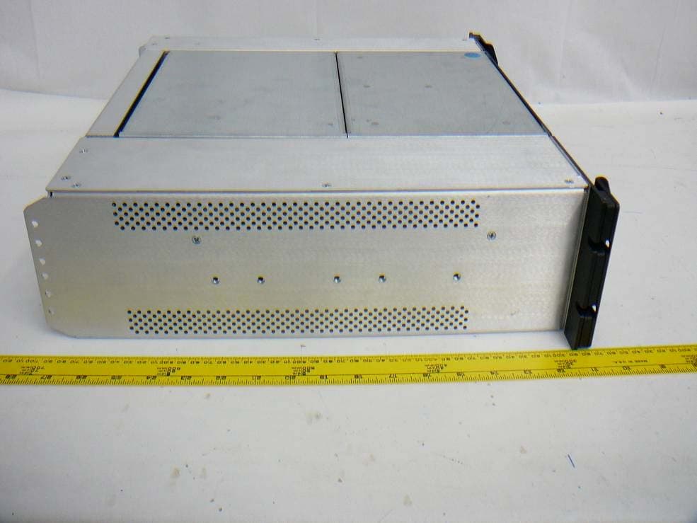
RBP-920DLRM
Jan 22, 2013Printer/Plotter, Direct Thermal Color
Equipment Class
DXX - Part 15 Low Power Communication Device Transmitter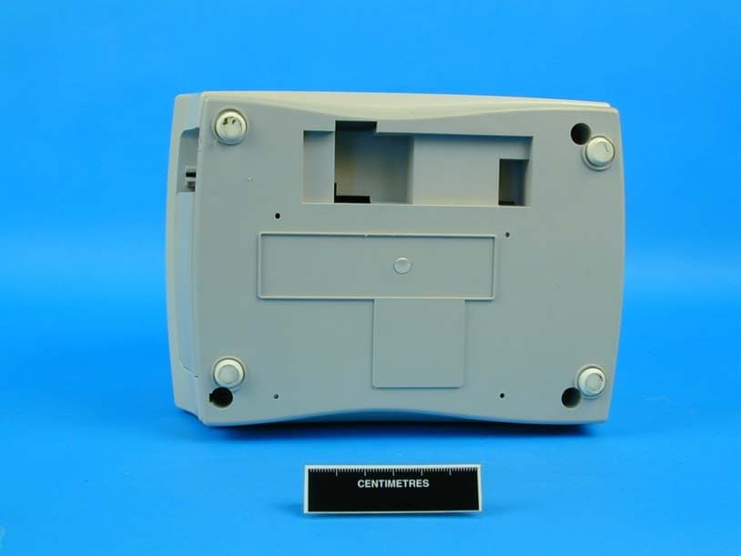
RBPMOD280
Sep 29, 2003Wireless Receipt Printer
Equipment Class
DSS - Part 15 Spread Spectrum Transmitter