RC5SMARTVP01Video Calling Device
Purple Communications, Inc.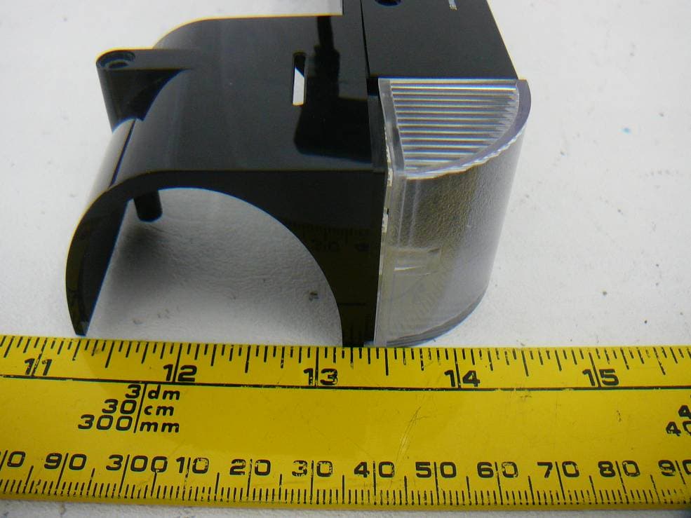
Click to zoom
Application Details
- Equipment Class
- DSC - Part 15 Security/Remote Control Transmitter
- Date of Grant
- Apr 03, 2013
- Application Purpose
- Original Equipment
- Date of Application
- Apr 03, 2013
- Equipment Note
- Video Calling Device
- Frequency Range
- 315.00000000 - 315.00000000
- Company
- Purple Communications, Inc.
- Country
- United States
Documents & Files
Document Text
Text extracted from the exhibit documents filed with the FCC. Open a document above to read the original.
Users Manual
PROPRIETARY DOCUMENTATION – INTERNAL DISTRIBUTION ONLY Smart VP by Purple Professional Installation Training Manual Drafted & Updated by: Last Updated Monday, April 01, 2013 at 5:21:39 PM Rev No: Revision Date Prepared Approval A1 2/14/2013 Josh Kramer A2 3/27/2015 Antony Galdi SmartVP – Professional Installation Manual – Page 2 of 6 PROPRIETARY DOCUMENTATION – INTERNAL DISTRIBUTION ONLY Table of Contents Requirements for Installation ......................................................................................................... 3 Preferred Placement of the SmartVP Unit ................................................................................... 3 HDMI Cable Connection ..................................................................................................................... 3 Power Connections for the SmartVP ............................................................................................. 3 Pairing The Remote Controller ....................................................................................................... 4 (Optional) Ethernet Cable Connection .......................................................................................... 4 (Optional) Sonic Alert Wireless Network Configuration ........................................................ 4 (Optional) Wired flasher device installation .............................................................................. 5 (Optional) USB Accessory Devices ................................................................................................. 5 Mounting and Removing the SmartVP from TelyHD device .................................................. 5 Device Compliance Notice ................................................................................................................. 6 SmartVP – Professional Installation Manual – Page 3 of 6 PROPRIETARY DOCUMENTATION – INTERNAL DISTRIBUTION ONLY Requirements for Installation In order to complete the installation, you must have the following install kit (boxed with SmartVP). • SmartVP unit (already assembled with TelyHD device – for mounting and unmounting instructions see appendix A) • HDMI Cable • Ethernet Cable • Remote Control ( +2x AAA batteries) • Power Adapters (x2) • Additional Information cards or notices for the user Preferred Placement of the SmartVP Unit The ideal installation location for the SmartVP unit is on top of the television set, centered across it’s width. 1. The base of the combined SmartVP unit has an unfolding panel. Rotate this panel open to approximately 90-‐degrees from the base panel. This creates a bracket to securely place the SmartVP atop the television set. 2. Adjust angle of lower base panel to offer the optimal balance of the unit atop the television. 3. Ensure the SmartVP sits centered (approximately) on the television set. HDMI Cable Connection Use the provided HDMI cable in the installation kit or use an existing/available HDMI connection to an available television input. 1. Connect the HDMI cable to the back of the SmartVP in the HDMI port. 2. Connect the other end of the cable to an available (free) HDMI input on the television. Power Connections for the SmartVP Use the provided two power adapters to power both the SmartVP and the TelyHD devices. Note the order in which the devices are connected to power. 1. Connect both power adapters to available power outlets or use an optional power strip. 2. Connect the DC plug of one power outlet to the SmatVP first. The power outlet is located next to the “Flasher Acc” port and is labeled “Power”. 3. Connect the DC plug of the second power outlet to the SmatVP first. The power outlet is located next to the unlabeled USB data cable port. The power port is labeled “5V DC”. SmartVP – Professional Installation Manual – Page 4 of 6 PROPRIETARY DOCUMENTATION – INTERNAL DISTRIBUTION ONLY Pairing The Remote Controller The remote controller should arrive pre-‐paired to the specific unit. If a case arises where the remote controller is not pre-‐paired to the device, pairing must be completed for the user. Note the SmartVP must be turned ON to pair the remote controller. 1. Press and hold 1 and 9 buttons for 5 seconds on PURPLE remote. After 5 seconds you can observe the red color LED will flash at “POWER BUTTON” for three times. Please see the below picture. 2. Once remote is successfully paired the power button will flash 3x. (Optional) Ethernet Cable Connection Use the provided Ethernet cable in the installation kit or use an existing/available Ethernet connection to the user’s Local Area Network (LAN). Note that the user may opt to use their WiFi network to connect the SmartVP – if so, skip this step. 1. Connect the Ethernet cable to the back of the SmartVP in the RJ-‐45 Ethernet port. 2. Connect the other end of the cable to an available (free) Ethernet input either located in a wall-‐outlet, or directly to the router. (Optional) Sonic Alert Wireless Network Configuration In order to communicate with the user’s existing SonicAlert wireless ringer network in the home, the SmartVP must be configured to use those network settings the Sonic Alert base station (DB-‐100) is configured to use. Press and hold 1 and 9 buttons for 5 seconds. We can observe flashing red LED for 3 times. Pre-‐Production Example Photo Only SmartVP – Professional Installation Manual – Page 5 of 6 PROPRIETARY DOCUMENTATION – INTERNAL DISTRIBUTION ONLY 1. With the user’s assistance, locate the base station (DB-‐100) unit. It will be plugged into a power outlet. 2. Remove the base station and turn over, the back of the base station exposes the network DIP switch settings. 3. Using a coin, rotate the top access panel on the SmartVP clockwise approx. 15 degrees. 4. Remove the coin access panel. 5. Using a pen or fine pointed device, ensure that the DIP switch positions are identical to those on the base unit (DB-‐100). 6. Re-‐close the access panel. (Optional) Wired flasher dev…
Text truncated - open the document above for the full version.
External Photos
Purple Communication, Inc. FCC ID: RC5SMARTVP01 Report Number: R1212214-231 Page 30 of 36 FCC Part 15.231 Test Report 10 EXHIBIT C - EUT PHOTOGRAPHS 10.1 EUT - Top View 10.2 EUT - Bottom View Purple Communication, Inc. FCC ID: RC5SMARTVP01 Report Number: R1212214-231 Page 31 of 36 FCC Part 15.231 Test Report 10.3 EUT – Side View 1 10.4 EUT – Side View 2 Purple Communication, Inc. FCC ID: RC5SMARTVP01 Report Number: R1212214-231 Page 32 of 36 FCC Part 15.231 Test Report 10.5 EUT – Front View 10.6 EUT – Rear View
ID Label/Location Info
Purple Communication, Inc. FCC ID: RC5SMARTVP01 Report Number: R1212214-231 Page 26 of 36 FCC Part 15.231 Test Report 8 EXHIBIT A - FCC ID LABELING AND WARNING STATEMENT 8.1 FCC ID Label Requirement FCC §2.925 Identification of equipment (a) Each equipment covered in an application for equipment authorization shall bear a nameplate or label listing the following: (1) FCC Identifier consisting of the two elements in the exact order specified in §2.926. The FCC Identifier shall be preceded by the term FCC ID in capital letters on a single line, and shall be of a type size large enough to be legible without the aid of magnification. Example: FCC ID: XXX123 Where: XXX—Grantee Code, 123—Equipment Product Code 8.2 FCC ID Label Contents and Location FCC ID: XXX-XXXXXX
Internal Photos
Purple Communication, Inc. FCC ID: RC5SMARTVP01 Report Number: R1212214-231 Page 33 of 36 FCC Part 15.231 Test Report 10.7 EUT – Main PCB Board Component View 10.8 EUT – Main PCB Board Solder View Purple Communication, Inc. FCC ID: RC5SMARTVP01 Report Number: R1212214-231 Page 34 of 36 FCC Part 15.231 Test Report 10.9 EUT – TX Module Component View 10.10 EUT – TX Module Solder View Purple Communication, Inc. FCC ID: RC5SMARTVP01 Report Number: R1212214-231 Page 35 of 36 FCC Part 15.231 Test Report 10.11 EUT – RX Module Component View 10.12 EUT – RX Module Solder View Purple Communication, Inc. FCC ID: RC5SMARTVP01 Report Number: R1212214-231 Page 36 of 36 FCC Part 15.231 Test Report 10.13 EUT – AC/DC Adaptor --- END OF REPORT ---
Test Report
Note: This test report is prepared for the customer shown above and for the device described herein. It may not be duplicated or used in part without prior written consent from Bay Area Compliance Laboratories Corp. This report must not be used by the customer to claim product certification, approval, or endorsement by A2LA* or any agency of the Federal Government. * This report may contain data that are not covered by the A2LA accreditation and are marked with an asterisk “*” (Rev.3) FCC PART 15.231 TEST AND MEASUREMENT REPORT For Purple Communications, Inc. 595 Menlo Drive, Rocklin, CA 95765, USA FCC ID: RC5SMARTVP01 Report Type: Original Report Product Type: Add on Accessory to the TelyHD Unit Prepared By: Wei Sun Report Number: R1212214-231 Report Date: 2013-04-02 Reviewed By: Quinn Jiang Test Engineer Bay Area Compliance Laboratories Corp. 1274 Anvilwood Avenue, Sunnyvale, CA 94089, USA Tel: (408) 732-9162 Fax: (408) 732 9164 Purple Communication, Inc. FCC ID: RC5SMARTVP01 Report Number: R1212214-231 Page 2 of 36 FCC Part 15.231 Test Report TABLE OF CONTENTS 1 GENERAL INFORMATION .............................................................................................................................. 5 1.1 PRODUCT DESCRIPTION FOR EQUIPMENT UNDER TEST (EUT) ........................................................................ 5 1.2 MECHANICAL DESCRIPTION OF EUT .............................................................................................................. 5 1.3 OBJECTIVE ...................................................................................................................................................... 5 1.4 RELATED SUBMITTAL(S)/GRANT(S) ............................................................................................................... 5 1.5 TEST METHODOLOGY ..................................................................................................................................... 5 1.6 MEASUREMENT UNCERTAINTY ...................................................................................................................... 5 1.7 TEST FACILITY ............................................................................................................................................... 6 2 SYSTEM TEST CONFIGURATION ................................................................................................................. 7 2.1 JUSTIFICATION ................................................................................................................................................ 7 2.2 EUT EXERCISE SOFTWARE ............................................................................................................................. 7 2.3 EQUIPMENT MODIFICATIONS .......................................................................................................................... 7 2.4 SPECIAL EQUIPMENT ...................................................................................................................................... 7 2.5 LOCAL SUPPORT EQUIPMENT ......................................................................................................................... 7 2.6 EUT INTERNAL CONFIGURATION DETAILS ..................................................................................................... 7 2.7 EXTERNAL I/O CABLING LIST AND DETAILS .................................................................................................. 7 3 SUMMARY OF TEST RESULTS ...................................................................................................................... 8 4 FCC §15.207(A) – AC LINE CONDUCTED EMISSIONS .............................................................................. 9 4.1 APPLICABLE STANDARDS ............................................................................................................................... 9 4.2 TEST SETUP .................................................................................................................................................... 9 4.3 TEST PROCEDURE ........................................................................................................................................... 9 4.4 TEST SETUP BLOCK DIAGRAM ...................................................................................................................... 10 4.5 CORRECTED AMPLITUDE & MARGIN CALCULATION .................................................................................... 10 4.6 TEST EQUIPMENT LIST AND DETAILS ........................................................................................................... 11 4.7 TEST ENVIRONMENTAL CONDITIONS ............................................................................................................ 11 4.8 SUMMARY OF TEST RESULTS ........................................................................................................................ 11 4.9 CONDUCTED EMISSIONS TEST PLOTS AND DATA ......................................................................................... 12 5 FCC §15.231(A) – PERIODIC TRANSMISSION ........................................................................................... 14 5.1 APPLICABLE STANDARD ............................................................................................................................... 14 5.2 MEASUREMENT PROCEDURE ........................................................................................................................ 14 5.3 TEST SETUP BLOCK DIAGRAM ...................................................................................................................... 15 5.4 TEST EQUIPMENT LIST AND DETAILS ........................................................................................................... 15 5.5 TEST ENVIRONMENTAL CONDITIONS ..................................................................................................…
Text truncated - open the document above for the full version.
Test Setup Photos
Purple Communication, Inc. FCC ID: RC5SMARTVP01 Report Number: R1212214-231 Page 27 of 36 FCC Part 15.231 Test Report 9 EXHIBIT B - TEST SETUP PHOTOGRAPHS 9.1 Conducted Emissions - Front View 9.2 Conducted Emissions - Rear View Purple Communication, Inc. FCC ID: RC5SMARTVP01 Report Number: R1212214-231 Page 28 of 36 FCC Part 15.231 Test Report 9.3 Radiated Emissions - Front View 9.4 Radiated Emissions - Rear View (Below 1 GHz) Purple Communication, Inc. FCC ID: RC5SMARTVP01 Report Number: R1212214-231 Page 29 of 36 FCC Part 15.231 Test Report 9.5 Radiated Emissions - Rear View (Above 1 GHz)
Contact Information
Applicant
Chris Talbot(Project Manager)
Test Firm
Bay Area Compliance Laboratories Corp.Lisa Tang
Technical Specifications
| # | Rule Parts | Frequency Range | Power Output |
|---|---|---|---|
| 1 | 15.231 | 315 MHz - 315 MHz | - |
Other Applications from Purple Communications, Inc.
RC5RF101A
Feb 26, 2013SMARTVP REMOTE CONTROL
Equipment Class
DXX - Part 15 Low Power Communication Device Transmitter