RE6HUSKY24G2.4 GHz FHSS Transmitter
Hubsung Plastics Ltd.
Click to zoom
Application Details
- Equipment Class
- DSS - Part 15 Spread Spectrum Transmitter
- Date of Grant
- Dec 19, 2010
- Application Purpose
- Original Equipment
- Date of Application
- Dec 19, 2010
- Equipment Note
- 2.4 GHz FHSS Transmitter
- Frequency Range
- 2402.99969500 - 2480.98065200
- Company
- Hubsung Plastics Ltd.
- Country
- South Korea
Documents & Files
Document Text
Text extracted from the exhibit documents filed with the FCC. Open a document above to read the original.
Users Manual
Order Number : GETEC-C1-10-196 FCC Part 15 subpart C Test Report Number : GETEC-E3-10-126 Page 1 / 1 EUT Type: 2.4 GHz FHSS Transmitter FCC ID.: RE6HUSKY24G APPENDIX H : USER’S MANUAL User's Guide 2.4G HUSKY Proton Radio Control, Inc. PO Box 957681 Duluth GA USA 30096 Loading battery pack tap hook 1 2 Adaptation for Left-hander Antenna Installation Top View M steering trim throttle trim mode enter / stopwatch down / idle up / start +, - / dual rate Steering wheel Touch buttons* Trigger LCD Antenna Stopwatch button Battery box Body Control Panel 1. Remove the 4 screws from the bottom of control panel. 2. Separate the control panel and the body by slowly pulling apart. 3. Rotate the control panel 180 o degrees and carefully reinsert the control panel into the body. Be carefully not to bend the pin connectors inside. 4. Reinstall the 4 screws. Specification of Husky 2.4G, transmitter Modulation : 2.4 GHz, FHSS Size : 185 X 120 X 270 mm (7.28" X 4.72" X 10.63") We ight : 482 g (17 oz) Power requirements : Li-ion battery pack (DC 7.4 V, 720mAh) Operating temperature : 0 ~ 40 o C Specification of Cube 3, receiver Modulation : 2.4 GHz, FHSS Size : 38 X 30.5 X 16.5 mm (1.5" X 1.2" X 0.65") We ight : 14.80 g (0.52 oz) Power requirements : DC 3.5 ~ 10.0 V Operating temperature : 0 ~ 40 o C How to establish link between the transmitter and the receiver Each transmitter has an individually assigned unique ID code. In order to start operation, the receiver must be linked with the ID code of the transmitter to which it is being paired. Once the link is made, the ID code is stored in the receiver and no further linking is necessary unless the receiver needs to be used with another transmitter. Linking procedure: 1. From the transmitter's [BIND] menu, choose ID LINK and press Enter . 2. Power the Cube receiver and press the bind button (red LED above the slots) until the LED changes to blue. 3. Confirm the link establishment by watching for servo movement when steering or triggering. * Touch button : The control buttons are touch sensors and they only require a light finger touch to operate. Important Note: To avoid an unintended operation, touch sensor buttons are automatically deactivated and go into hold mode after 10 seconds of inactivity. T o reactivate the touch sensor buttons, simply rotate the steering wheel to left or right. Caution: Do not over tighten the antenna. Once installed, leave it installed. Repeated removal and reinstall can loosen the antenna base and damage the connections, causing reduced range and/or loss of signal. - Charging Use the charger included in this product. With the battery installed in HUSKY 2.4G, plug the charger into the charging port on the side. Charging takes approximately 2 hours. Rear View USB port power LED power switch charging port Li-ion Battery Installation and Charging 1. Lightly press the hook and pull up the tap to open the cover. 2. Place the Li-ion battery pack (NB-2LH) in the b ottom and slide towards the front so that the battery pack is tightly sit. 3. Close the cover. Steering servo slot Throttle servo slot AUX & Power slot Bind button Cube 3, Antenna-less Receiver Approval - FCC This device complies with Part 15 of the FCC Rules. Operation is subject to thefollowing two conditions: (1) this device may not cause harmful interference, and (2) thisdevice must accept any interference received, including interference that may cause undesired operation. Any changes or modifications not expressly approved by the party responsiblefor compliance could void the authority to operate equipment. The antenna(s) used for thistransmitter must not be co-located or operating inconjunction with any otherantenna or transmitter. - Federal Communication Commission (FCC) Radiation Exposure Statement For Husky 2.4G, transmitter : FCC ID RE6HUSKY24G The remote device is approved as hand-held and hand-operation only portable (relative to hand) device which is normally operated at 5 cm from a person's body For Cube 3, receiver : FCC ID RE6CUBE24G3 The device and the antenna for this device must be installed to ensure a minimum separation distance of 20 cm or more from a person's body. Other operating configurations should be avoided. - CE Hereby, Hubsung Plastics Ltd. declares that this 2.4 GHz radio control system is in comd and compliance with the essential requirements and other relevant provisions of Directive 1999/5/EC. The R&TTE (Radio Equipment & Telecommunications Terminal Equipment) directive is the new European directive relating to radio equipment and telecommunications transmission equipment. It also covers the collective recognition of the conformity of such equipment. One part of the R&TTE directive regulates the introduction and operation of radio systems in the European Community. An important change is the abolition of approval. The manufacturer or importer must subject radio equipment to a conformity appraisal process before that equipment is introduced. The CE symbol is attached to the device to indicate that it conforms with the valid European norms. An exclamation mark is also to be attached to radio transmitting equipment, to indicate that the permissible frequencies are not yet uniform throughout Europe. This requirement applies to all the countries included in the list attached. It is essential to note that these radio control systems may only be operated on the approved frequencies, as listed in the table. Please note that the user bears the responsibility for compliance with this requirement, and for ensuring that the radio system complies with the directives. In Germany the requirement to purchase a license for the operation of 2.4 GHz systems remains in effect; please refer to the operating instructions, or the separate sheet included with them. Flow Chart [FUNCTION] CH1 : STEERING CH2 : THROTTLE [BIND] ID LINK COUNTRY ALL [SYSTEM] MODEL STOPWATCH CONTRAST : 10 [MODEL] SELECT 1 NAME HUSKY COPY TO None MRV 4.4V RESET OFF [STEERING] REV OFF EPA L …
Text truncated - open the document above for the full version.
Cover Letter(s)
SCS-F18: Project and Product Certification Representative Authorization Letter Page 1 of 2 Rev 2.0 2206 Ringwood Avenue San Jose, CA 95131 Tel: 408-526-1188 Fax: 408-526-1088 Email: [email protected] Project and Product Certification Representative Authorization Letter Reason for Amendment (current / obsolete) Revision History Approved Date From To Initial Release (current) 1.0 1.0 Nov-14-2006 Revised wording (current) 1.0 2.0 Sept–25-2007 SCS-F18: Project and Product Certification Representative Authorization Letter Page 2 of 2 Rev 2.0 Hubsung Plastics, Ltd. 182-4, Dodang-dong, Wonmi-gu, Bucheon, Gyounggi-do, Korea Tel: +82-31-427-8904, Fax: +82-31-427-8904 December 08, 2010 To: SIEMIC, INC. 2206 Ringwood Avenue, San Jose, CA 95131 USA Dear Sir/Madam, Re: Project and Product Certification Representative Authorization Letter We, Hubsung Plastics, Ltd., hereby authorize SIEMIC, INC. to act as a Certification Body for certifying for the following project(s): Product Name: RF Remote Controller FCC ID: RE6HUSKY24G We affirm that between SIEMIC and Hubsung Plastics, Ltd., any difference in understanding, including test plan, measurement methods, applicable standards and relevant procedures and processes have been resolved prior to commencement of testing activities. Sincerely, --------------------------------------------- Seongho Ko, President Hubsung Plastics, Ltd.
Cover Letter(s)
Confidentiality Request Letter Reason for Amendment (current / obsolete) Revision History Approved Date From To Initial Release (current) 1.0 1.0 Nov-14-2006 Hubsung Plastics, Ltd. 182-4, Dodang-dong, Wonmi-gu, Bucheon, Gyounggi-do, Korea Tel: +82-31-427-8904, Fax: +82-31-427-8904 SCS-F19: Confidentiality Request Letter Rev 1.0 Nov 14, 2006 Federal Communications Commission Authorization and Evaluation Division December 08, 2010 Confidentiality Request regarding application for certification of FCC ID: RE6HUSKY24G We hereby request confidential treatment of information accompanying this application as outlined below: Exhibit Type File Name BLOCK DIAGRAM HUSKY24G_BlkDia.pdf SCHEMETIC DIAGRAM HUSKY24G_SchDia.pdf OPERATIONAL DESCRIPTION HUSKY24G_OpeDes.pdf PART LIST HUSKY24G_PrtLst.pdf The above materials contain trade secrets and proprietary information not customarily released to the public. The public disclosure of these materials may be harmful to the applicant and provide unjustified benefits to its competitors. In addition to above mentioned documents, pursuant to Public DA 04-1705 of the Commission’s policy, in order to comply with the marketing regulations in 47 CFR 2.803 and the importation rules in 47 CFR 2.1204, while ensuring that business sensitive information remains confidential until the actual marketing of newly authorized devices. We are requesting the commission to grant short-term confidentiality request on the following Exhibit Type File Name TEST SET UP PHOTOS HUSKY24G_Tsup.pdf EXTERNAL PHOTOGRAPHS HUSKY24G_ExtPho.pdf INTERNAL PHOTOGRAPHS HUSKY24G_IntPho.pdf USER’S MANUAL HUSKY24G_UseMan.pdf The applicant understands that pursuant to Section 0.457 of the Rules, disclosure of this application and all accompanying documentation will not be made before the date of the Grant for this application. Sincerely, --------------------------------------------- Seongho Ko, President Hubsung Plastics, Ltd.
External Photos
Order Number : GETEC-C1-10-196 FCC Part 15 subpart C Test Report Number : GETEC-E3-10-126 Page 1 / 6 EUT Type: 2.4 GHz FHSS Transmitter FCC ID.: RE6HUSKY24G APPENDIX F : EXTERNAL PHOTOGRAPHS Order Number : GETEC-C1-10-196 FCC Part 15 subpart C Test Report Number : GETEC-E3-10-126 Page 2 / 6 EUT Type: 2.4 GHz FHSS Transmitter FCC ID.: RE6HUSKY24G < Front > Order Number : GETEC-C1-10-196 FCC Part 15 subpart C Test Report Number : GETEC-E3-10-126 Page 3 / 6 EUT Type: 2.4 GHz FHSS Transmitter FCC ID.: RE6HUSKY24G < Rear > Order Number : GETEC-C1-10-196 FCC Part 15 subpart C Test Report Number : GETEC-E3-10-126 Page 4 / 6 EUT Type: 2.4 GHz FHSS Transmitter FCC ID.: RE6HUSKY24G < Upper > Order Number : GETEC-C1-10-196 FCC Part 15 subpart C Test Report Number : GETEC-E3-10-126 Page 5 / 6 EUT Type: 2.4 GHz FHSS Transmitter FCC ID.: RE6HUSKY24G < Bottom #1 > Order Number : GETEC-C1-10-196 FCC Part 15 subpart C Test Report Number : GETEC-E3-10-126 Page 6 / 6 EUT Type: 2.4 GHz FHSS Transmitter FCC ID.: RE6HUSKY24G < Bottom #2 >
ID Label/Location Info
Order Number : GETEC-C1-10-196 FCC Part 15 subpart C Test Report Number : GETEC-E3-10-126 Page 1 / 2 EUT Type: 2.4 GHz FHSS Transmitter FCC ID.: RE6HUSKY24G APPENDIX B : ID SAMPLE LABEL & LOCATION Order Number : GETEC-C1-10-196 FCC Part 15 subpart C Test Report Number : GETEC-E3-10-126 Page 2 / 2 EUT Type: 2.4 GHz FHSS Transmitter FCC ID.: RE6HUSKY24G LABELLING REQUIREMENTS The label shown shall be permanently affixed at a conspicuous location on the device and be readily visible to the user at the time of purchase. ID Label ID Label Location of EUT ID Label
Internal Photos
Order Number : GETEC-C1-10-196 FCC Part 15 subpart C Test Report Number : GETEC-E3-10-126 Page 1 / 12 EUT Type: 2.4 GHz FHSS Transmitter FCC ID.: RE6HUSKY24G APPENDIX G : INTERNAL PHOTOGRAPHS Order Number : GETEC-C1-10-196 FCC Part 15 subpart C Test Report Number : GETEC-E3-10-126 Page 2 / 12 EUT Type: 2.4 GHz FHSS Transmitter FCC ID.: RE6HUSKY24G < Inside / RF module location > RF module Order Number : GETEC-C1-10-196 FCC Part 15 subpart C Test Report Number : GETEC-E3-10-126 Page 3 / 12 EUT Type: 2.4 GHz FHSS Transmitter FCC ID.: RE6HUSKY24G < RF module front > Order Number : GETEC-C1-10-196 FCC Part 15 subpart C Test Report Number : GETEC-E3-10-126 Page 4 / 12 EUT Type: 2.4 GHz FHSS Transmitter FCC ID.: RE6HUSKY24G < RF module rear > Order Number : GETEC-C1-10-196 FCC Part 15 subpart C Test Report Number : GETEC-E3-10-126 Page 5 / 12 EUT Type: 2.4 GHz FHSS Transmitter FCC ID.: RE6HUSKY24G < Board #1 front > Order Number : GETEC-C1-10-196 FCC Part 15 subpart C Test Report Number : GETEC-E3-10-126 Page 6 / 12 EUT Type: 2.4 GHz FHSS Transmitter FCC ID.: RE6HUSKY24G < Board #1 rear > Order Number : GETEC-C1-10-196 FCC Part 15 subpart C Test Report Number : GETEC-E3-10-126 Page 7 / 12 EUT Type: 2.4 GHz FHSS Transmitter FCC ID.: RE6HUSKY24G < Board #2 front > Order Number : GETEC-C1-10-196 FCC Part 15 subpart C Test Report Number : GETEC-E3-10-126 Page 8 / 12 EUT Type: 2.4 GHz FHSS Transmitter FCC ID.: RE6HUSKY24G < Board #2 rear > Order Number : GETEC-C1-10-196 FCC Part 15 subpart C Test Report Number : GETEC-E3-10-126 Page 9 / 12 EUT Type: 2.4 GHz FHSS Transmitter FCC ID.: RE6HUSKY24G < Antenna front > Order Number : GETEC-C1-10-196 FCC Part 15 subpart C Test Report Number : GETEC-E3-10-126 Page 10 / 12 EUT Type: 2.4 GHz FHSS Transmitter FCC ID.: RE6HUSKY24G < Antenna rear > Order Number : GETEC-C1-10-196 FCC Part 15 subpart C Test Report Number : GETEC-E3-10-126 Page 11 / 12 EUT Type: 2.4 GHz FHSS Transmitter FCC ID.: RE6HUSKY24G < Battery front > Order Number : GETEC-C1-10-196 FCC Part 15 subpart C Test Report Number : GETEC-E3-10-126 Page 12 / 12 EUT Type: 2.4 GHz FHSS Transmitter FCC ID.: RE6HUSKY24G < Battery rear >
RF Exposure Info
Order Number : GETEC-C1-10-196 FCC Certification Test Report Number : GETEC-E3-10-126 Page 1 / 2 EUT Type: 2.4 GHz FHSS Transmitter FCC ID.: RE6HUSKY24G APPENDIX L : RF EXPOSURE EVALUATION Order Number : GETEC-C1-10-196 FCC Certification Test Report Number : GETEC-E3-10-126 Page 2 / 2 EUT Type: 2.4 GHz FHSS Transmitter FCC ID.: RE6HUSKY24G RF Exposure Evaluation 1.1 Applicable Standard According to §15.247(e)(i) and §1.1307(b)(1), systems operating under the provisions of this section shall be operated in a manner that ensures that the public is not exposed to radio frequency energy level in excess of the Commission’s guidelines. According to KDB 447498 DS01 Ver 04, no Hand SAR required if power is lower than the following threshold: Device is hand-operated device; its antenna will be less than 5cm, but more than 5 cm from human body. So Body SAR is not required. Husky 2.4G Hand SAR Frequency Range Center frequency (MHz) 1000*[f (GHz) ] -0.5 Hand SAR Limitation (mW) Low Frequency (MHz) High Frequency(MHz) 2 402.999 695 2 480.980 652 2 441.990 174 645 Body SAR Frequency Range Center frequency (MHz) 300*[f (GHz) ] -0.5 Body SAR Limitation (mW) Low Frequency (MHz) High Frequency(MHz) 2 402.999 695 2 480.980 652 2 441.990 174 193 Maximum measured transmitter power Conducted Power (mW) Max Antenna Gain (dBi) EIRP (mW) 22.1 2.0 34.99 Threshold at which no SAR required is 193 mW. Maximum Tx power is 34.99 mW EIRP. Conclusion: No SAR is required. No Simultaneous transmission occurs.
Test Report
Order Number : GETEC-C1-10-196 FCC Class B Certification Test Report Number: GETEC-E3-10-126 Page2 / 37 EUT Type: 2.4 GHz FHSS Transmitter FCC ID.: RE6HUSKY24G CONTENTS 1. GENERAL INFORMATION ...................................................................................................................................... 4 2. INTRODUCTION ........................................................................................................................................................ 5 3. PRODUCT INFORMATION ...................................................................................................................................... 6 3.1 DESCRIPTION OF EUT .............................................................................................................................................. 6 3.2 SUPPORT EQUIPMENT / CABLES USED ..................................................................................................................... 8 3.3 MODIFICATION ITEM(S) ........................................................................................................................................... 8 4. DESCRIPTION OF TESTS ......................................................................................................................................... 9 4.1 TEST CONDITION ...................................................................................................................................................... 9 5. ANTENNA REQUIREMENT - §15.203 ..................................................................................................................... 9 5.1 DESCRIPTION OF ANTENNA ...................................................................................................................................... 9 5.2 CONDUCTED EMISSION .......................................................................................................................................... 10 5.3 RADIATED EMISSION .............................................................................................................................................. 11 6. CONDUCTED EMISSION ........................................................................................................................................ 12 6.1 OPERATING ENVIRONMENT ................................................................................................................................... 12 6.2 TEST SET-UP ........................................................................................................................................................... 12 6.3 MEASUREMENT UNCERTAINTY.............................................................................................................................. 12 6.4 LIMIT ...................................................................................................................................................................... 13 6.5 TEST EQUIPMENT USED .......................................................................................................................................... 13 6.6 TEST DATA FOR CONDUCTED EMISSION ................................................................................................................ 13 7. NUMBER OF HOPPING FREQUENCY USED ..................................................................................................... 16 7.1 OPERATING ENVIRONMENT ................................................................................................................................... 16 7.2 TEST SET-UP (LAY O U T) .......................................................................................................................................... 16 7.3 LIMIT ...................................................................................................................................................................... 16 7.4 TEST EQUIPMENT USED .......................................................................................................................................... 16 7.5 TEST RESULT .......................................................................................................................................................... 16 8. DWELL TIME ON EACH CHANNEL .................................................................................................................... 20 8.1 OPERATING ENVIRONMENT ................................................................................................................................... 20 8.2 TEST SET-UP (LAY O U T) .......................................................................................................................................... 20 8.3 LIMIT ...................................................................................................................................................................... 20 8.4 TEST EQUIPMENT USED .......................................................................................................................................... 20 8.5 TEST RESULT .......................................................................................................................................................... 20 9. CHANNEL BANDWIDTH ........................................................................................................................................ 22 9.1 OPERATING ENVIRONMENT ................................................................................................................................... 22 9.2 TEST SET-UP (LAY O U T) .......................................................................................................................................... 22 9.3 LIMIT ...................................................................................................................................................................... 22 9.4 TEST EQUIPMENT USED ....................…
Text truncated - open the document above for the full version.
Test Setup Photos
Order Number : GETEC-C1-10-196 FCC Part 15 subpart C Test Report Number : GETEC-E3-10-126 Page 1 / 5 EUT Type: 2.4 GHz FHSS Transmitter FCC ID.: RE6HUSKY24G APPENDIX E : TEST SET UP PHOTOGRAPHS Order Number : GETEC-C1-10-196 FCC Part 15 subpart C Test Report Number : GETEC-E3-10-126 Page 2 / 5 EUT Type: 2.4 GHz FHSS Transmitter FCC ID.: RE6HUSKY24G Conducted Test Picture (Front) Conducted Test Picture (Rear) Order Number : GETEC-C1-10-196 FCC Part 15 subpart C Test Report Number : GETEC-E3-10-126 Page 3 / 5 EUT Type: 2.4 GHz FHSS Transmitter FCC ID.: RE6HUSKY24G Radiated Test Picture (Front): 30 MHz to 1 000 MHz Radiated Test Picture (Rear): 30 MHz to 1 000 MHz Order Number : GETEC-C1-10-196 FCC Part 15 subpart C Test Report Number : GETEC-E3-10-126 Page 4 / 5 EUT Type: 2.4 GHz FHSS Transmitter FCC ID.: RE6HUSKY24G Radiated Test Picture (X axis): Above 1 GHz Radiated Test Picture (Y axis): Above 1 GHz Order Number : GETEC-C1-10-196 FCC Part 15 subpart C Test Report Number : GETEC-E3-10-126 Page 5 / 5 EUT Type: 2.4 GHz FHSS Transmitter FCC ID.: RE6HUSKY24G Radiated Test Picture (Z axis): Above 1 GHz
Contact Information
Applicant
Mr. Seongho Ko(Manager)
Test Firm
GUMI UNIVERSITY EMC CENTERTea-Sig Park
Technical Specifications
| # | Rule Parts | Frequency Range | Power Output |
|---|---|---|---|
| 1 | 15C | 2.40 GHz - 2.48 GHz | 22.10 mW |
Other Applications from Hubsung Plastics Ltd.
RE6CUBE24G3
Dec 19, 20102.4 GHz FHSS Transmitter
Equipment Class
DSS - Part 15 Spread Spectrum Transmitter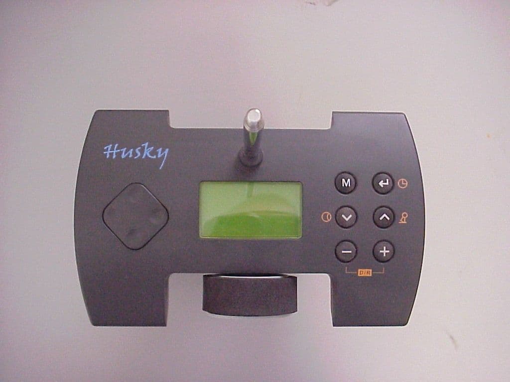
RE6HUSKY27
Oct 22, 2003Husky FM 2 Channel FM Radio Control System
Equipment Class
TNB - Licensed Non-Broadcast Station Transmitter