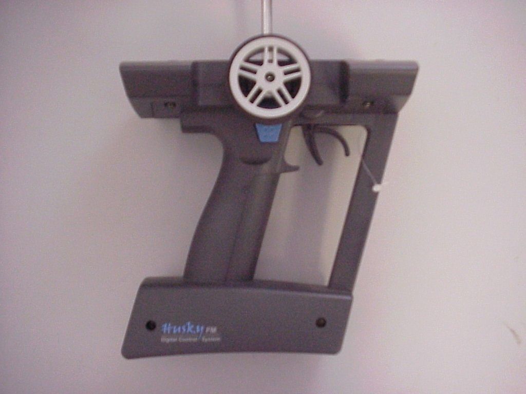
RE6HUSKY27Husky FM 2 Channel FM Radio Control System
Hubsung Plastics Ltd.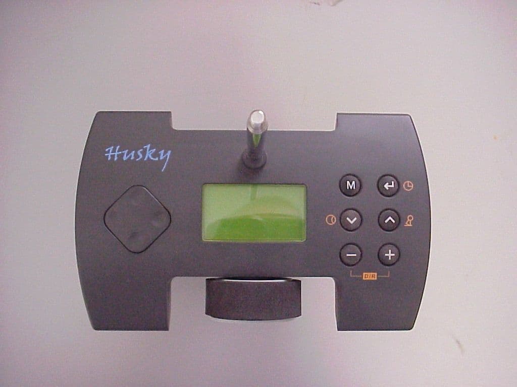
Click to zoom
Application Details
- Equipment Class
- TNB - Licensed Non-Broadcast Station Transmitter
- Date of Grant
- Oct 22, 2003
- Application Purpose
- Original Equipment
- Date of Application
- Aug 21, 2003
- Equipment Note
- Husky FM 2 Channel FM Radio Control System
- Frequency Range
- 26.99500000 - 27.25500000
- Company
- Hubsung Plastics Ltd.
- Country
- South Korea
Documents & Files
Document Text
Text extracted from the exhibit documents filed with the FCC. Open a document above to read the original.
Users Manual
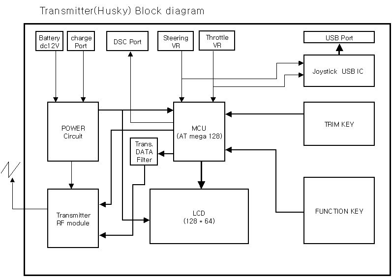
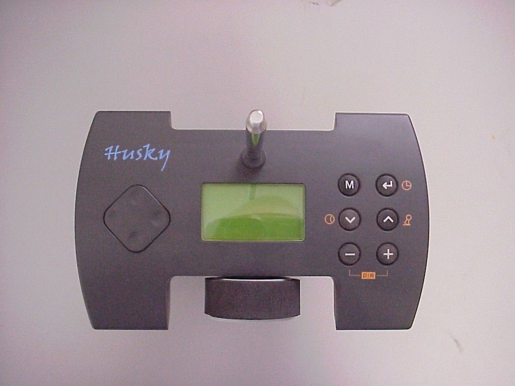
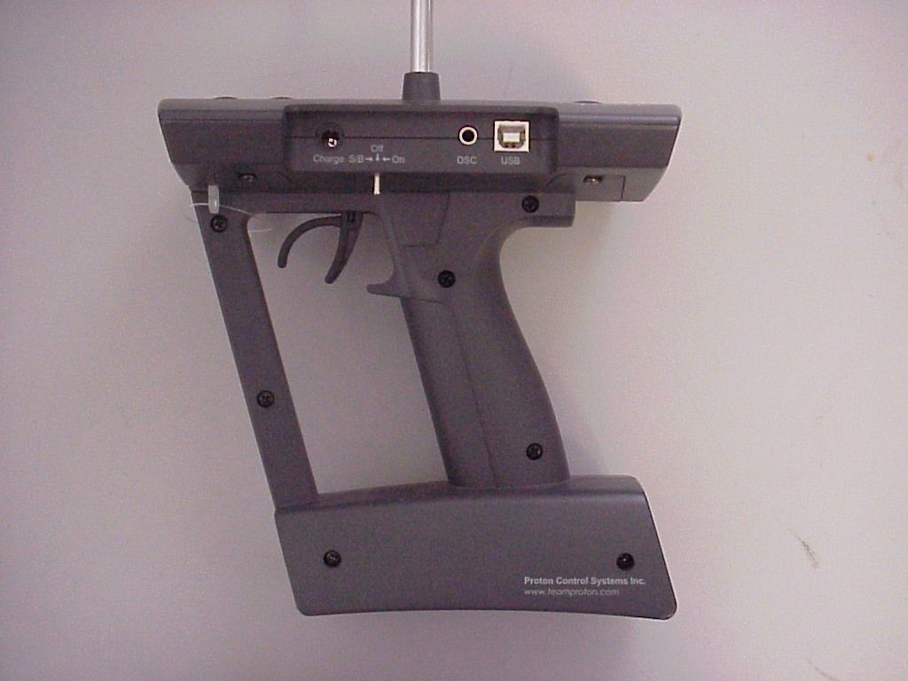
HUSKY FM 2 Channel FM Radio Control System USER'S GUIDE Proton Control Systems Inc. Preparation Husky Adaptation for Left-hander Antenna Installation Loading the Batteries Charging Power switch Direct Servo Control USB Connection Standing Specification Ken Installation Frequency Setting Specification Safety Transmitter and receiver Operating Frequency Battery Maintenance Data Setting Control panel Normal display Function map Direct Access Functions Digital Trim Dual Rate Stopwatch System Mode Functions Model Name Trim Rate LCD Contrast Frequency Data Copy Pit Mode Functions Model Select Setting Level Servo Reverse Sub Trim Data Reset Circuit Mode Functions End Point Adjustment Response Steering Speed 2-Step Steering Speed Throttle Speed 2-Step Throttle Speed Start 3-Step ABS ABS Auto Steering Control Punch Idle Up Limited Warranty Approvals Table of Contents Features Thank you for purchasing a Proton Control Systems product. Before operating your Husky transmitter and Ken receiver, please read this manual carefully. Then retain it for future reference. 1. Features No crystal needed to change frequencies The frequencies of most transmitters and receivers are adjusted by changing the crystals. Enthusiasts who want to change frequencies must purchase extra crystal sets to prevent interference between same frequencies. To complicate matters further there are so many types of crystals based on modulation (FM/AM, PPM/PCM), conversion type (Single/Dual) and Radio makers. To solve this problem, Proton Control Systems adapted PLL (Phase Loop Lock) technology to your Husky transmitter and Ken receiver. The preferred frequencies are selectable sim ply by pressing buttons. Works with all popular FM transmitters & receivers Your Husky transmitter and Ken receiver are each compatible with all popular FM trans mitters and receivers. These include A class (Futaba TM , Hitec TM ) and B class (JR TM , Sanwa TM , KO TM ). This flexibility allows you to use different brand transmitters and receivers. USB port for PC game control Your Husky is more than a transmitter for your R/C models. Use your Husky transmitter to control your PC games too! Husky comes with a built-in USB port for connecting to your personal computer. Now you can practice at home before the big race. Better still, your race will never be rained out. Easy to change grip direction for left or right-hander Husky's symmetrical design allows you to quickly change format from right- to left-hand grip. Just unscrew 4 screws and rotate the body 180 O degrees. Who's better than Husky? Programming features The program settings on your Husky consist of 3 levels (Expert, Standard, Basic) and 3 modes (System, Pit, Circuit). The programs are simple to set, but offer many powerful func tions. Features Preparation 2. Preparation - Husky, 2 Channel FM transmitter Adaptation for Left-hander Huskies are produced for right-handers. However the grip direction can be changed for left-handers. 1. Make sure that the Power switch in set to OFF. 2. Carefully remove the 4 screws from the bottom cover of the control panel. 3. Separate control panel and body 4. Rotate head 180 O degrees and reinstall the 4 screws being careful not over tight en them. Antenna Steering Wheel LCD Trim Button Trigger Time lever Grip Battery Box Control Panel Body Function Buttons Preparation Antenna Installation The antenna included with your Husky is safely stored in a slot under the control panel. To remove the antenna, pull back the plastic retainer cap located at the front of your Husky transmitter, then slide the antenna out. Insert the base of the antenna into the antenna receptacle at the top of the control panel. Then screw the antenna clockwise until it is firmly attached. Be careful not to over tighten the an tenna. NOTE The antenna should be fully extended while transmitting. Otherwise the operating range of the system will be reduced and loss of control may occur. Loading the batteries Your Husky transmitter requires 8 AA batteries (not included). Alkaline batteries will provide power for approximately 7 hours of use. The battery box is located at the bottom of the transmitter body. 1. Make sure that the Power switch is set to the OFF position. 2. Release the hook and pop up automatically the battery cover. 3. Pull down the battery holder and disconnector from the battery case and install the batteries into the holder. 4. Plug in the connector and replace battery holder into the battery case and push down the battery cover until it locks in place. Charging The changing jack is located on the back side of control panel and marked "12V ". Before start charging, make sure the rechargeable NiCd batteries are instal led and power switch is set to the OFF position. For charging the transmitter, the charger must have below specification. Otherwise it may damage the transmitter or not be charged. Input voltage : 110V 60 Hz for USA, 230V 50 Hz for Europe Output voltage : DC 10.8V 150 mAh Charge jack polarity : Typical slow charge rates are DC 10.8V, 150mA for 12 hours, while most Sanyo brand AAs can be charged at up to 1 Amp. NOTE Never charge a dry cell type (Non-NiCd) battery. Charging a non NiCd battery may damage the transmitter, and could cause the battery electrolyte to leak and cause additional damage. Preparation Power switch The Power switch is a small toggle switch located back of the Control Panel near the base of the antenna. It can be set to On, Off and Standby (S/B) modes. Power On and Off is same as any other electronic device. Standby (S/B) allows you to pro gram all functions without transmitting a signal. This is useful for making adjust ments while not affecting others that may be on the same frequency. Standby (S/B) mode also uses about 2/3 less power. If you plan to work in a programming mode for any length of time or use your Husky as a PC game controller, using Standby will extend your battery life. "STB" appears on the LCD display in Standby (S/B) mode. Battery…
Text truncated - open the document above for the full version.
Cover Letter(s)
August 15, 2003 Federal Communications Commission Equipment Approval Services Post Office Box 358315 Pittsburgh, PA 15251-5315 To Whom It May Concern: The following submittal is to apply for equipment certification for Hubsung’s 2-Channel FM Transmitter Model Husky FM. Garwood Laboratories, Inc. will be submitting this package in behalf of the applicant, Hubsung Plastics Ltd. A letter authorizing Garwood Laboratories as an agent for Hubsung Plastics Ltd is available upon request. Thank you, Arnie Tapia Sr. EMC Technician Garwood Laboratories, Inc
ID Label/Location Info
FCC ID Label and Location: FCC ID Label and Location Bottom side of the transmitter
Operational Description
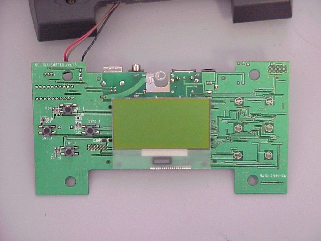
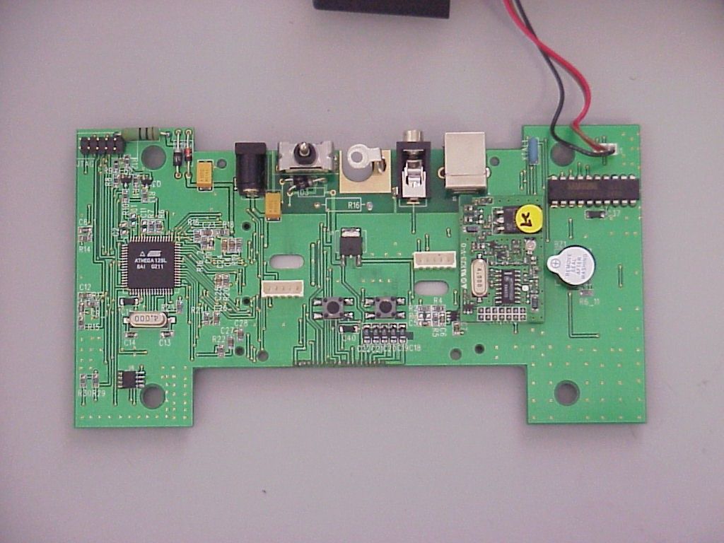
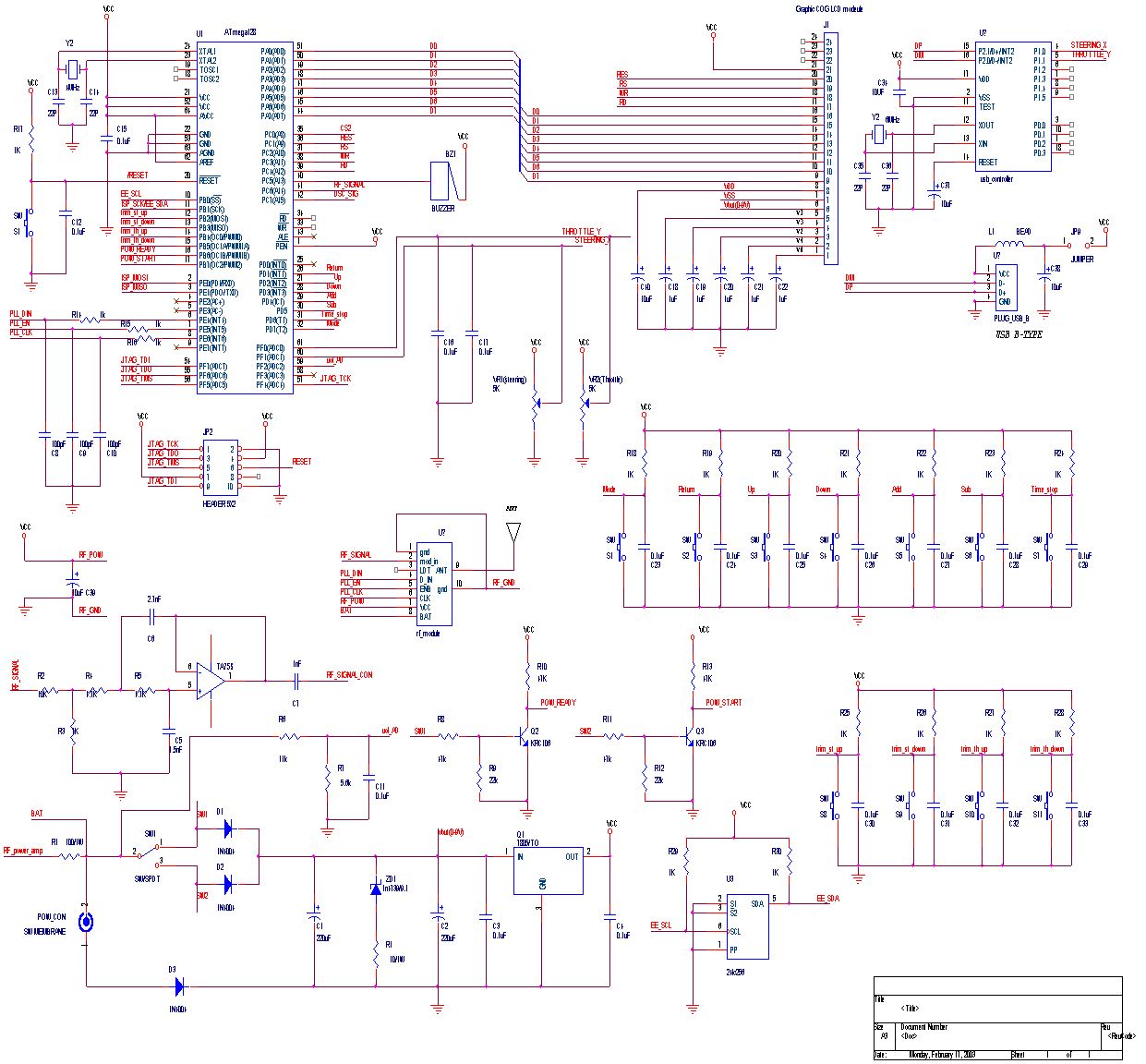
Operational Description: The unit under test is a 2 Channel FM Transmitter that is used for remote control of surface R/C models. The transmitter can only be tuned to any one of the six allowed operating frequencies in the 27MHz band (26.995, 27.045, 27.095, 27.145, 27.195, or 27.255MHz). The preferred frequency is selectable by pressing the trim buttons. The transmitter can operate from either 8 ‘AA’ size Alkaline batteries or 8 ‘AA’ size NiCd rechargeable batteries.
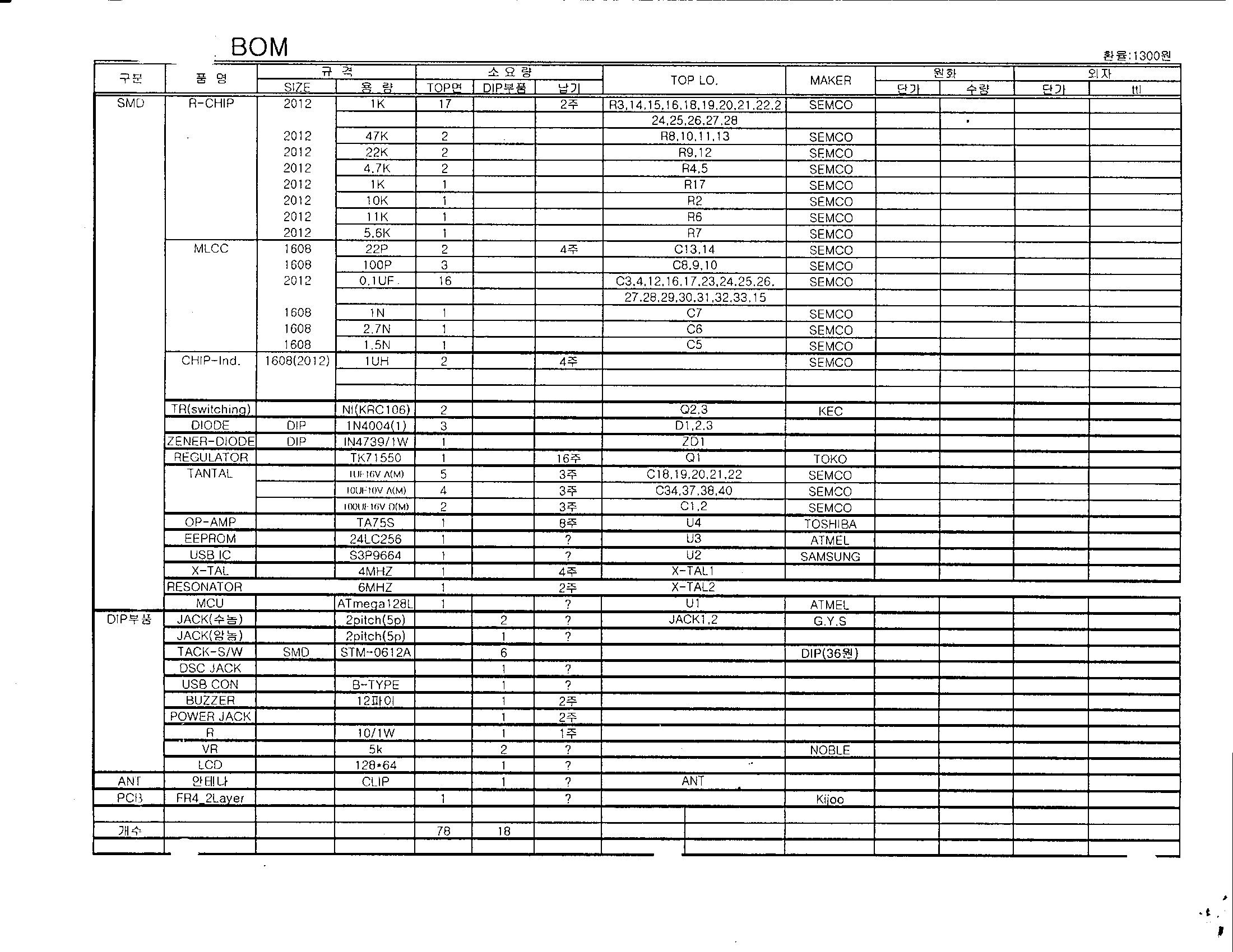
Parts List/Tune Up Info
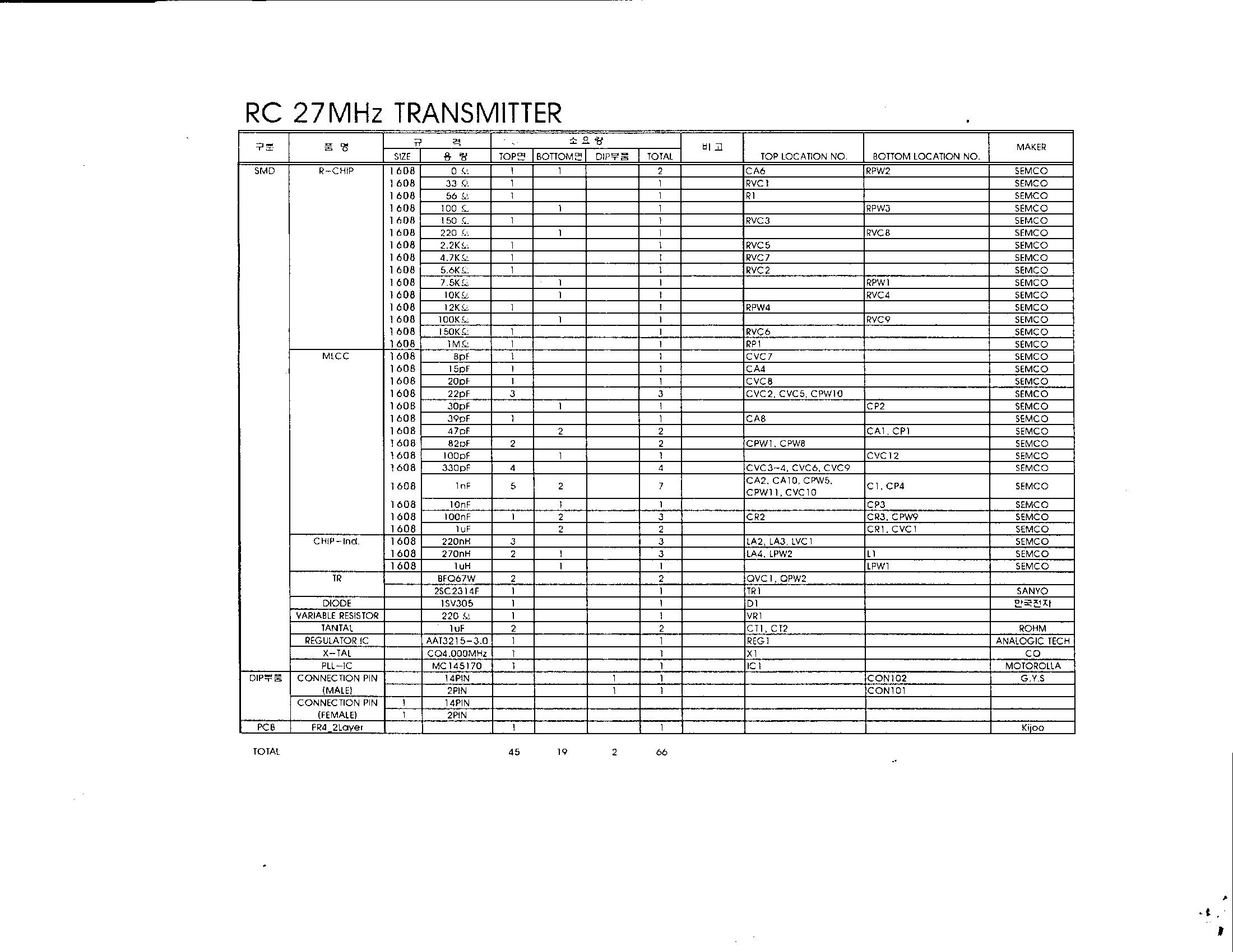
Re: FCC ID RE6HUSKY27 Correspondence Reference Number: 25712 The applicant, in response to the tune up request, provided the following information. 1. Adjustment procedure for the transmitter in order to insure it is transmitting at 27MHz There are two adjustment procedure as below. a. Hardware. The transmitting frequency is fixed by PLL (Phase Loop Lock) circuit. We set the PLL circuit in TX module to lock VCO (Voltage Controlled Oscillator) only for 27MHz. So it is impossible to transmitting other frequencies with 27Mhz set. b. Software The 27MHz set displays only authorized 27 MHz frequencies on the LCD. So it is impossible to select other frequencies at the 27MHz set. The frequency change procedure is available on the manual.
Test Report
1 of 18 FCC TEST REPORT for HUBSUNG 2 Channel FM Transmitter, 27MHz Model: Husky FM ARWOOD LABORATORIES, INC. Your Most Trusted Name in Testing Since 1954. G Date: 8/13/03 EUT: Husky Transmitter 2 of 18 GARWOOD LABORATORIES, INC. TESTING AND ENGINEERING SERVICES FCC TEST REPORT Certification for FCC Part 95 Subpart C – Radio Control (R/C) Radio Service Report for: HUBSUNG 2 CHANNEL FM TRANSMITTER, 27MHZ Model: Husky FM Prepared For: Hubsung Plastics, Ltd. 182-3 Dodang-dong Wonmi-ku Bucheon-city Kyounggi-do, South Korea, 420-130 Prepared By: Garwood Laboratories, Inc 7829 Industry Avenue Pico Rivera, CA 90660 Issued: August 13, 2003 GARWOOD LABORATORIES, INC. 7829 Industry Avenue, Pico Rivera, CA 90660 Report No: FR25428-E FCC TEST REPORT FOR HUBSUNG Date: 8/13/03 EUT: Husky Transmitter 3 of 18 Testing Services Since 1954 ® “EXCELLENCE BUILT ON INTEGRITY” RESPONSIBLE SIGNATURES This report is intended for the use by the organization to whom it is addressed, and will not be made available to any other parties without the expressed written consent of the aforementioned organization. This report shall not be reproduced, except in full, without the written approval of Garwood Laboratories, Inc. DOCUMENT HISTORY Revision Issue Date Affected Page(s) Description Of Modifications Revised By Approved By N/C Initial release GARWOOD LABORATORIES, INC. 7829 Industry Avenue, Pico Rivera, CA 90660 Report No: FR25428-E FCC TEST REPORT FOR HUBSUNG Date: 8/13/03 EUT: Husky Transmitter 4 of 18 Testing Services Since 1954 ® “EXCELLENCE BUILT ON INTEGRITY” CLIENT INFORMATION Purchase Order 1351 Company Name Address City, State, Country Zip Hubsung Plastics Ltd. 182-3 Dodang-dong Wonmi-ku Bucheon-city, Kyounggi-do, South Korea, 420-130 Contact Name E-mail Mr. Seongho Ko, Manager [email protected] GARWOOD INFORMATION EMC Test Laboratory Address City, State, Zip Code Phone Fax Web Site Garwood Laboratories, Inc. 7829 Industry Avenue Pico Rivera, CA 90660 (562) 949-2727 (562) 949-8757 www.garwoodtestlabs.com Contact Name Title Tony Masone EMC Manager Test Personnel Test Dates Arnulfo Tapia – EMC Sr. Technician 1/17/03, 2/21/03 GARWOOD LABORATORIES, INC. 7829 Industry Avenue, Pico Rivera, CA 90660 Report No: FR25428-E FCC TEST REPORT FOR HUBSUNG Date: 8/13/03 EUT: Husky Transmitter 5 of 18 Testing Services Since 1954 ® “EXCELLENCE BUILT ON INTEGRITY” ACCREDITATIONS: The Open Area Test Site (OATS) and measurement facilities used to collect the test data are located at Garwood Laboratories, Incorporated test facility in Pico Rivera, California. This facility has been fully described in a report submitted to the FCC and accepted in a letter dated 22 April 2002, Registration Number 534174. The test facility is also recognized, certified, or accredited by the following organizations: This site has been registered and fully described in a report filed with the (FCC) Federal Communications Commission. The acceptance letter from the FCC is maintained in our files. Registration Number: 534174. Date of listing: April 22, 2002. Garwood Laboratories is an authorized test laboratory for the DoC process. Garwood Laboratories, Inc. has been assessed in accordance with ISO 17025 and with ITI's assessment criteria. Based upon this assessment, Technology International (Europe), Ltd. has granted approval for specifications implementing the EU Directive on EMC (89/336/EEC). The scope of the approval was provided on a Schedule of Assessment supplied with a certificate and is available upon request. Certificate Number: 01-051, effective through August 5, 2002, or until the next agreed assessment date (October 11, 2002). Garwood Laboratories, Inc. is registered by Industry Canada for performance of measurements and complies with RSS 212, Issue 1 (Provisional). Reference IC 3298, Dated: January 8, 2003. Garwood Laboratories, Inc. is authorized, by joint agreement with Korea Electric Testing Institute (KETI), to perform required and necessary South Korean Product Safety and EMC testing (including reports) according to the IEC and CISPR standards. Nmi (Nederlands Meetinstituut) Garwood Laboratories, Inc. has entered into a cooperative agreement with Nmi Certin B.V. of the Netherlands. This is a Notified Body for the R&TTE Directive and Maritime Directive as well as a Competent Body for the EMC Directive. GARWOOD LABORATORIES, INC. 7829 Industry Avenue, Pico Rivera, CA 90660 Report No: FR25428-E FCC TEST REPORT FOR HUBSUNG Date: 8/13/03 EUT: Husky Transmitter 6 of 18 Testing Services Since 1954 ® “EXCELLENCE BUILT ON INTEGRITY” TABLE OF CONTENTS MEASUREMENT / TECHNICAL REPORT SUMMARY.............................................................................7 1. GENERAL INFORMATION ...................................................................................................................8 1.1 Product Description.......................................................................................................8 1.2 Configuration of Tested System .....................................................................................8 2. TECHNICAL INFORMATION ...............................................................................................................9 2.1 Specifications .................................................................................................................9 2.2 Circuit Schematics .........................................................................................................9 2.3 Additional Circuit Information ......................................................................................9 3. PRODUCT LABELLING ......................................................................................................................10 3.1 FCC ID Label ..............................................................................................................10 3.2 Location of the Label on the EUT............................................................................…
Text truncated - open the document above for the full version.
Contact Information
Applicant
Mr. Seongho Ko(Manager)
Technical Contact
Garwood Laboratories, Inc.Arnie Tapia
[email protected]562-949-2727
7829 Industry Ave. · Pico Rivera, California · United States
Non-Technical Contact
Garwood Laboratories, Inc.Arnie Tapia
[email protected]562-949-2727
Technical Specifications
| # | Rule Parts | Frequency Range | Power Output | Emission | Tolerance |
|---|---|---|---|---|---|
| 1 | 95C | 26.995 MHz - 27.255 MHz | 845.00 µW | 8K00F1D | 0.0100000000 % |
Other Applications from Hubsung Plastics Ltd.

RE6HUSKY24G
Dec 19, 20102.4 GHz FHSS Transmitter
Equipment Class
DSS - Part 15 Spread Spectrum Transmitter
RE6CUBE24G3
Dec 19, 20102.4 GHz FHSS Transmitter
Equipment Class
DSS - Part 15 Spread Spectrum Transmitter