REP-1500R-1802.11a Mesh Networked Ethernet Service Point
Firetide Inc.
Click to zoom
Application Details
- Equipment Class
- NII - Unlicensed National Information Infrastructure TX
- Date of Grant
- Jan 18, 2005
- Application Purpose
- Original Equipment
- Date of Application
- Jan 18, 2005
- Equipment Note
- 802.11a Mesh Networked Ethernet Service Point
- Frequency Range
- 5745.00000000 - 5805.00000000
- Company
- Firetide Inc.
- Country
- United States
Documents & Files
Document Text
Text extracted from the exhibit documents filed with the FCC. Open a document above to read the original.
Users Manual
HotPoint 1500R Outdoor Wireless Mesh Router i Hardware Installation Guide HotPoint 1500R Outdoor Wireless Mesh Router wireless instant networks™ Hardware Installation Guide ii Hardware Installation Guide HotPoint 1500R Outdoor Wireless Mesh Router Part No. xxxxx Rev A ****Requires Part Number**** Copyright Notice © 2003-2004 Firetide, Inc. All rights reserved. Trademarks Firetide, the Firetide logo, Wireless Instant Networks, HotPoint are trademarks of Firetide, Inc. All other trademarks are the property of their respective owners. HotPoint 1500R Outdoor Wireless Mesh Router v HotPoint Limited End User Product Warranty Pursuant to all provisions described herein, Firetide products are warranted for one (1) year from the date of purchase against defects in the build materials and workmanship. Firetide also warrants that the Software will materially conform to the documentation supplied by Firetide with the Software. In the event that the Software fails to materially conform to the documentation and an authorized Firetide reseller is notified in writing of such failure within the warranty period, Firetide or its reseller shall use commercially reasonable efforts to promptly correct the nonconformity. Firetide does not warrant that the use of the Software will be uninterrupted or error free. Firetide does not warrant that the Products will meet any requirements or specifications of any End User Customer. This warranty applies to the entire Firetide product, including antennas and the AC power adapter. The above warranties are void if the alleged defect cannot be verified by Firetide or if, as determined by Firetide, the product failure was due to tampering, abuse, misuse, accident, shipping, handling, or storage; or if the product has been installed, used, or maintained in a manner not described in the product user manual, if the product has been altered In any way, or If product serialization has been altered. Any at-tempt to disassemble or repair the product by anyone other than Firetide immediately voids this warranty. This warranty applies only to the original End User purchaser of the product and may not be transferred to any other individual or entity. THE FOREGOING ARE THE EXCLUSIVE WARRANTIES APPLICABLE TO THE PRODUCT INCLUDING THE SOFTWARE, AND THE EXCLUSIVE REMEDY FOR DEFECTS IN THE PRODUCT. FIRETIDE DISCLAIMS ALL OTHER WARRANTIES, WHETHER EXPRESS, IMPLIED, STATUTORY OR OTHERWISE, INCLUDING BUT NOT LIMITED TO IMPLIED WARRANTIES OF MERCHANTABILITY, NON-INFRINGEMENT OR FITNESS FOR A PARTICULAR PURPOSE. SOME LAWS DO NOT ALLOW THE EXCLUSION OF IMPLIED WARRANTIES SO TO THAT EXTENT THIS LIMITATION MAY NOT APPLY TO YOU. In no event will Firetide be liable for any special, incidental, consequential, punitive or indirect damages whatsoever (including, without limitation, damages for loss of profits, business interruption, loss of information, or other pecuniary loss) arising out of the use or inability to use the product or the performance, interruption or failure of the product, irrespective of the cause of action, even if Firetide has been advised of the possibility of such damages. Firetide's cumulative liability for all claims arising out of or in connection with this warranty will not exceed the amount paid by the original End User purchaser to purchase the product. The amounts payable for the product are based in part on these limitations and these limitations shall apply not-withstanding the failure of essential purpose of any remedy. Some jurisdictions do not allow the exclusion or limitation of incidental or consequential damages, so to that extent the above limitations or exclusions may not apply to you. By using the product the original End User purchaser agrees to and is bound by these terms and conditions. In the event that a product fails to meet this warranty and Firetide’s authorized reseller is notified in writing of such failure within the warranty period, Firetide shall, at its own discretion, either repair the product or replace it with the same or a functionally-equivalent product free of charge. Replacement products may contain refurbished materials in whole or in part. Firetide will honor this warranty provided the product is returned through an authorized Firetide reseller or dealer with shipping charges prepaid, along with a proof of purchase describing the original purchase date and product serial numbers if applicable. The authorized reseller must acquire a Return Materials Authorization (RMA) number from Firetide prior to returning any product. Firetide does not accept shipments of defective products without shipping charges prepaid. Hardware Installation Guide iv Safety Instructions The HotPoint 1500R outdoor wireless mesh router must be installed by a qualified professional such as a licensed electrician. Failure to install this equipment properly may result in equipment damage and personal injury or death. Explanation of Graphical Symbols: This symbol is intended to alert the user to the presences of non-insulated dangerous voltage” that may be of sufficient magnitude to constitute a risk of lethal electric shock to persons. This symbol is intended to alert the user to the presence of important operating, maintaining and servicing instructions in the literature accompanying the 1500R. Failing to comply with this instruction may result in electrical shock. This symbol is intended to alert the user to the presence of important operating, maintaining and servicing instructions in the literature accompanying the 1500R. Failing to comply with this instruction may result in a hazard. Caution! Risk of electric shock! POWER LINES CAN BE LETHAL Do not install the HotPoint 1500R outdoor mesh router where possible contact with power lines can be made. Antennas, masts, towers, guy wires or cables may lean or fall and contact these lines. People may be injured or killed if they are touching or holding any part of equipment when it contacts electric lines. Make sure there …
Text truncated - open the document above for the full version.
Cover Letter(s)
Corporate Headquarters Hawaii Office 16795 Lark Avenue 928 Nuuanu Avenue, Suite 200 Los Gatos, California 95032 Honolulu, Hawaii 96817 TEL: 408-399-7771 TEL: 808-528-0007 www.firetide.com December 15, 2004 Federal Communications Commission Authorization and Evaluation Division Equipment Authorization Branch 7435 Oakland Mills Road Columbia, MD 21046 To whom it may concern: We, the undersigned, hereby authorize Compliance Engineering Services, Inc. to act on our behalf in all manners relating to application for equipment authorization, including signing of all documents relating to these matters. Any and all acts carried out by Compliance Engineering Service, Inc. on our behalf shall have the same effect as acts of our own. We, the undersigned, hereby certify that we are not subject to a denial of federal benefits, that includes FCC benefits, pursuant to Section 5301 of the Anti-Drug Abuse Act of 1988, 21 U.S.C. 853(a). This authorization is valid until further written notice from the applicant. Sincerely Yours, Keith Klemba Chief Architect firetide REMARK: 1. This authorization letter will be sent along with your application when filing with the FCC. 2. Please follow the format and type it on company letterhead and send original to us.
Cover Letter(s)
Corporate Headquarters Hawaii Office 16795 Lark Avenue 928 Nuuanu Avenue, Suite 200 Los Gatos, California 95032 Honolulu, Hawaii 96817 TEL: 408-399-7771 TEL: 808-528-0007 www.firetide.com October 21, 2004 Federal Communications Commission Equipment Authorization branch 7435 Oakland Mills Road Columbia, MD 21046 Re: Request for Confidentiality Gentlemen: In reference to the application under FCC ID: REP-1500R-1 and pursuant to Sections 0.457(d)(l)(ii) and 0.459 of the Commission’s Rules, the Applicant hereby requests confidential treatment of the accompanying information as outlined below: Schematics Block Diagrams Theory of Operation These documents contain detailed system and equipment description and related information about the product that firetide considers to be proprietary, confidential, and a custom design and, otherwise, would not release to the general public. Since this design is a basis from which future technological products will evolve, firetide considers that this information would be of benefit to its competitors, and that disclosure of the information in these documents would give competitors an unfair advantage in the market. Sincerely, Keith Klemba Chief Architect firetide
Cover Letter(s)
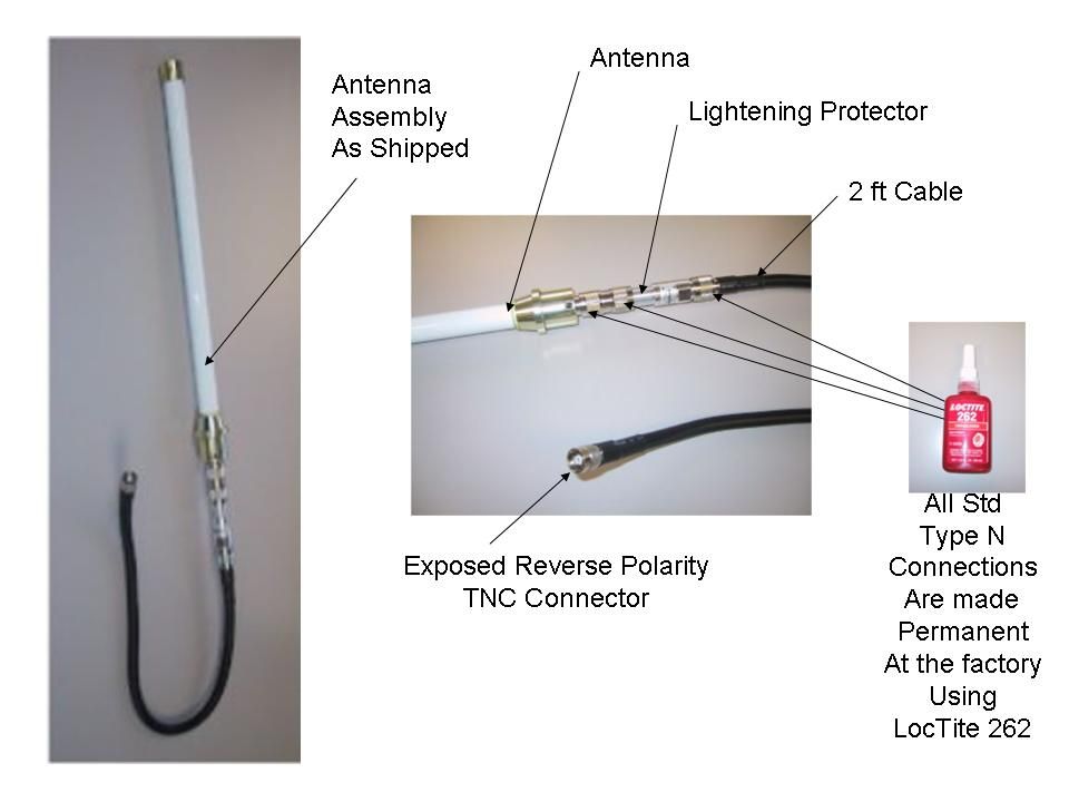
Chris Harvey From: Claire Hoque [[email protected]] Sent: Tuesday, January 18, 2005 2:15 PM To: Chris Harvey -TCB Cc: Chuck Cowden; Michael Heckrotte; Nancy Omron; Mike Kuo Subject: RE: answer to further questions: Firetide Inc. , FCC ID: REP-1500R-1, Assessment NO.: AN04T4317, Notice#1, 04U2975 Importance: High Page 1 of 4answer to further questions: Firetide Inc. , FCC ID: REP-1500R-1, Assessment NO.: AN04T4... 1/19/2005 Hi Chris, Here is client's answer for your last question. _________________________________________________________________________________________________________ It is an antenna field pattern showing the gain of our antenna in the 5.2GHz frequency. The gain pattern clearly shows the max gain to be well below 6Db which is the level below which any antenna is always acceptable. This antenna pattern is all that is available from the manufacturer as they only advertise the antenna for use in the 5.8 spectrum. We are had them test the antenna in 5.2 and 5.4 spectrum to determine that it would be ok for us to use in spite of it’s degraded performance. We tested the output in your lab and had the manufacturer run these pattern tests especially for us. I’m not sure what more I can do here. There is no marketing data sheet for the antenna in the 5.2 spectrum. Nevertheless, we have provided all the measurement information and tested the antenna in your lab. Please help me understand what they need beyond this detailed information? __________________________________________________________________________________________________________ Pls let us know your suggestion, thanks, Claire -----Original Message----- From: Chris Harvey [mailto:[email protected]] Sent: Friday, January 14, 2005 10:11 AM To: Claire Hoque Cc: Chuck Cowden; Michael Heckrotte; Nancy Omron; Mike Kuo Subject: RE: answer to further questions: Firetide Inc. , FCC ID: REP-1500R-1, Assessment NO.: AN04T4317, Notice#1, 04U2975 Claire, I have received and reviewed the additional documentation for the above referenced application. I still do not find the information regarding the Antenna gain and specifications in the 5.2GHz band as requested in the original question #4. 4. The Antenna specifications submitted document 8dBi at 5.8GHz bands but report states that this antenna has 4.5dBi gain at 5.2 GHz and. There is a photo of the antenna in the internal photo exhibit. Please provide the antenna specification that includes the 5.2GHz band. Please provide this antenna specification information including the antenna gain. Please contact me if you have any questions. Best regards, Chris Harvey Chris Harvey EMC Consultants, LLC [email protected] cell 443-622-3300 -----Original Message----- From: Claire Hoque [mailto:[email protected]] Sent: Wednesday, January 12, 2005 7:26 PM To: Chris Harvey -TCB; Chris Harvey Cc: Chuck Cowden; Michael Heckrotte; Nancy Omron; Mike Kuo Subject: answer to further questions: Firetide Inc. , FCC ID: REP-1500R-1, Assessment NO.: AN04T4317, Notice#1, 04U2975 Importance: High Hi Chris, Here are the answers to address your 12/19/04 questions. 2) Each application for Certification must stand alone. The FCC policy is that the schematics for all the RF circuitry be submitted for each Certification application, regardless of whether the RF module has been previously certified. Pls ask client to provide schematics for NI3-AT53V216. <answer>pls see the attachment, pls keep it confidential. <<5354mparies2F schematics.pdf>> 4) The Antenna Specification did not provide any additional information except the VSWR from 5.3 to 6.3 GHz. My #4 question below still needs to be addressed. <answer>pls see the attachment, pls keep it confidential. <<Antenna1GP-5808 5 .2GHz.doc>> 5) You state that the antenna connection is permanent and would be destroyed if removed. Please describe this in more detail, because the use of an N connector anywhere in the RF path is considered a standard connection (even on the lightning arrestor) unless a permanent connection (according to FCC definition) is used. If an epoxy is used, please provide detailed information on the epoxy (data sheet) and an indication of who applies the epoxy (manufacturer before shipping?). If the Lightning arrestor is part of this Certification, please provide a photograph of this along with the antenna. <answer>pls see the attachment. <<AntAssembly4.jpg>> Thanks, Claire -----Original Message----- From: Chris Harvey [mailto:[email protected]] Sent: Sunday, December 19, 2004 8:04 PM To: Claire Hoque; Chris Harvey Cc: Chuck Cowden; Michael Heckrotte; Nancy Omron; Mike Kuo Subject: RE: answer: Firetide Inc. , FCC ID: REP-1500R-1, Assessment NO.: AN04T4317, Notice#1, 04U2975 Claire, thank you for getting this information to me. I have reviewed the additional information and still have some questions: 1) Thank you for the authorization letter. 2) Each application for Certification must stand alone. The FCC policy is that the schematics for all the RF Page 2 of 4answer to further questions: Firetide Inc. , FCC ID: REP-1500R-1, Assessment NO.: AN04T4... 1/19/2005 circuitry be submitted for each Certification application, regardless of whether the RF module has been previously certified. 3) Thank you for the revised Installation manual. 4) The Antenna Specification did not provide any additional information except the VSWR from 5.3 to 6.3 GHz. My #4 question below still needs to be addressed. 5) You state that the antenna connection is permanent and would be destroyed if removed. Please describe this in more detail, because the use of an N connector anywhere in the RF path is considered a standard connection (even on the lightning arrestor) unless a permanent connection (according to FCC definition) is used. If an epoxy is used, please provide detailed information on the epoxy (data sheet) and an indication of who applies the epoxy (manufacturer before shipping?). If the Lightning arrestor is part of this Certification, please provide a photo…
Text truncated - open the document above for the full version.
ID Label/Location Info
PROPOSED FCC ID LABEL AND LOCATION FIRETIDE INC. This device complies with Part 15 of the FCC Rules. Operation is subject to the following two conditions: (1) this device may not cause harmful interference, and (2) this device must accept any interference received, including interference that may cause undesired operation. FCC ID: REP-1500R-1 FCC ID LABEL LOCATION
Parts List/Tune Up Info
0 0 H-PLANE FIELD PATTERNS 0 0 E-PLANE FIELD PATTERNS
Parts List/Tune Up Info
| Products | 5.8GHz Antennas | Omnidirectional Antennas | Unit :mm Return Loss VSWR Electrical Properties Frequency Range: 5750~5850 MHz Impedance: 50 OHMS 5 SWR: 1.3 Gain: 8 dBi Radiation: Omni Polarization: Vertical E-PLANE FIELD PATTERNS Page 1 of 2 Everitme Communications Co., LTD --- antennas, antenna, base antennas, bluetooth ante... 9/22/2004http://www.ep.com.tw/1gp-5808.htm Mechanical Properties Connector: N ( FEMALE) Weight: 370 g Radiator: Copper Radome: Fiberglass Mounting: Zinc Guide Pipe: Aluminum Alloy Bracket: Aluminum Alloy * Mast kit Accepted 22- 24 mast diameter H-PLANE FIELD PATTERNS Download Installation guide Note: To obtain optimal results in extending wireless range with antenna installations, it is recommended that a qualified professional installer is consulted for site survey and proper installation. [ BAC K] [ TOP] Evertime Communications Co., Ltd Copyright 2003 All Rights Reserved. Page 2 of 2 Everitme Communications Co., LTD --- antennas, antenna, base antennas, bluetooth ante... 9/22/2004http://www.ep.com.tw/1gp-5808.htm
RF Exposure Info
REPORT NO: 04U2975-1B DATE: OCTOBER 12, 2004 EUT: Wireless 802.11 a Mesh Networked Ethernet Service Point FCC ID: REP-1500R-1 Page 20 of 95 COMPLIANCE CERTIFICATION SERVICES DOCUMENT NO: CCSUP4031A 561F MONTEREY ROAD, MORGAN HILL, CA 95037 USA TEL: (408) 463-0885 FAX: (408) 463-0888 This report shall not be reproduced except in full, without the written approval of CCS. This document may be altered or revised by Compliance Certification Services personnel only, and shall be noted in the revision section of the document. 7.1.3. MAXIMUM PERMISSIBLE EXPOSURE LIMITS §1.1310 The criteria listed in Table 1 shall be used to evaluate the environmental impact of human exposure to radio-frequency (RF) radiation as specified in §1.1307(b), except in the case of portable devices which shall be evaluated according to the provisions of §2.1093 of this chapter. REPORT NO: 04U2975-1B DATE: OCTOBER 12, 2004 EUT: Wireless 802.11 a Mesh Networked Ethernet Service Point FCC ID: REP-1500R-1 Page 21 of 95 COMPLIANCE CERTIFICATION SERVICES DOCUMENT NO: CCSUP4031A 561F MONTEREY ROAD, MORGAN HILL, CA 95037 USA TEL: (408) 463-0885 FAX: (408) 463-0888 This report shall not be reproduced except in full, without the written approval of CCS. This document may be altered or revised by Compliance Certification Services personnel only, and shall be noted in the revision section of the document. CALCULATIONS Given E = √ (30 * P * G) / d and S = E ^ 2 / 3770 where E = Field Strength in Volts/meter P = Power in Watts G = Numeric antenna gain d = Distance in meters S = Power Density in milliwatts/square centimeter Combining equations and rearranging the terms to express the distance as a function of the remaining variables yields: d = √ ((30 * P * G) / (3770 * S)) Changing to units of Power to mW and Distance to cm, using: P (mW) = P (W) / 1000 and d (cm) =100 * d (m) yields d = 100 * √ ((30 * (P / 1000) * G) / (3770 * S)) d = 0.282 * √ (P * G / S) where d = distance in cm P = Power in mW G = Numeric antenna gain S = Power Density in mW/cm^2 Substituting the logarithmic form of power and gain using: P (mW) = 10 ^ (P (dBm) / 10) and G (numeric) = 10 ^ (G (dBi) / 10) yields d = 0.282 * 10 ^ ((P + G) / 20) / √ S Equation (1) where d = MPE distance in cm P = Power in dBm G = Antenna Gain in dBi S = Power Density Limit in mW/cm^2 Equation (1) and the measured peak power is used to calculate the MPE distance. REPORT NO: 04U2975-1B DATE: OCTOBER 12, 2004 EUT: Wireless 802.11 a Mesh Networked Ethernet Service Point FCC ID: REP-1500R-1 Page 22 of 95 COMPLIANCE CERTIFICATION SERVICES DOCUMENT NO: CCSUP4031A 561F MONTEREY ROAD, MORGAN HILL, CA 95037 USA TEL: (408) 463-0885 FAX: (408) 463-0888 This report shall not be reproduced except in full, without the written approval of CCS. This document may be altered or revised by Compliance Certification Services personnel only, and shall be noted in the revision section of the document. LIMITS From §1.1310 Table 1 (B), S = 1.0 mW/cm^2 RESULTS No non-compliance noted: NOTE: For mobile or fixed location transmitters, the minimum separation distance is 20 cm, even if calculations indicate that the MPE distance would be less. ModePower DensityOutputAntennaMPE LimitPowerGainDistance (mW/cm^2)(dBm)(dBi)(cm) 802.11a1.017.133.302.96
RF Exposure Info
REPORT NO: 04U2975-1B DATE: OCTOBER 12, 2004 EUT: Wireless 802.11 a Mesh Networked Ethernet Service Point FCC ID: REP-1500R-1 Page 45 of 95 COMPLIANCE CERTIFICATION SERVICES DOCUMENT NO: CCSUP4031A 561F MONTEREY ROAD, MORGAN HILL, CA 95037 USA TEL: (408) 463-0885 FAX: (408) 463-0888 This report shall not be reproduced except in full, without the written approval of CCS. This document may be altered or revised by Compliance Certification Services personnel only, and shall be noted in the revision section of the document. 7.2.3. MAXIMUM PERMISSIBLE EXPOSURE LIMITS §1.1310 The criteria listed in Table 1 shall be used to evaluate the environmental impact of human exposure to radio-frequency (RF) radiation as specified in §1.1307(b), except in the case of portable devices which shall be evaluated according to the provisions of §2.1093 of this chapter. REPORT NO: 04U2975-1B DATE: OCTOBER 12, 2004 EUT: Wireless 802.11 a Mesh Networked Ethernet Service Point FCC ID: REP-1500R-1 Page 46 of 95 COMPLIANCE CERTIFICATION SERVICES DOCUMENT NO: CCSUP4031A 561F MONTEREY ROAD, MORGAN HILL, CA 95037 USA TEL: (408) 463-0885 FAX: (408) 463-0888 This report shall not be reproduced except in full, without the written approval of CCS. This document may be altered or revised by Compliance Certification Services personnel only, and shall be noted in the revision section of the document. CALCULATIONS Given E = √ (30 * P * G) / d and S = E ^ 2 / 3770 where E = Field Strength in Volts/meter P = Power in Watts G = Numeric antenna gain d = Distance in meters S = Power Density in milliwatts/square centimeter Combining equations and rearranging the terms to express the distance as a function of the remaining variables yields: d = √ ((30 * P * G) / (3770 * S)) Changing to units of Power to mW and Distance to cm, using: P (mW) = P (W) / 1000 and d (cm) =100 * d (m) yields d = 100 * √ ((30 * (P / 1000) * G) / (3770 * S)) d = 0.282 * √ (P * G / S) where d = distance in cm P = Power in mW G = Numeric antenna gain S = Power Density in mW/cm^2 Substituting the logarithmic form of power and gain using: P (mW) = 10 ^ (P (dBm) / 10) and G (numeric) = 10 ^ (G (dBi) / 10) yields d = 0.282 * 10 ^ ((P + G) / 20) / √ S Equation (1) where d = MPE distance in cm P = Power in dBm G = Antenna Gain in dBi S = Power Density Limit in mW/cm^2 Equation (1) and the measured peak power is used to calculate the MPE distance. REPORT NO: 04U2975-1B DATE: OCTOBER 12, 2004 EUT: Wireless 802.11 a Mesh Networked Ethernet Service Point FCC ID: REP-1500R-1 Page 47 of 95 COMPLIANCE CERTIFICATION SERVICES DOCUMENT NO: CCSUP4031A 561F MONTEREY ROAD, MORGAN HILL, CA 95037 USA TEL: (408) 463-0885 FAX: (408) 463-0888 This report shall not be reproduced except in full, without the written approval of CCS. This document may be altered or revised by Compliance Certification Services personnel only, and shall be noted in the revision section of the document. LIMITS From §1.1310 Table 1 (B), S = 1.0 mW/cm^2 RESULTS No non-compliance noted: NOTE: For mobile or fixed location transmitters, the minimum separation distance is 20 cm, even if calculations indicate that the MPE distance would be less. ModePower DensityOutputAntennaMPE LimitPowerGainDistance (mW/cm^2)(dBm)(dBi)(cm) 802.11a1.015.298.004.12
Test Report
FCC CFR47 PART 15 SUBPART E CERTIFICATION TEST REPORT FOR WIRELESS 802.11a MESH NETWORKED ETHERNET SERVICE POINT MODEL NUMBER: 1500R-0101-NAM FCC ID: REP-1500R-1 REPORT NUMBER: 04U2975-1B ISSUE DATE: OCTOBER 12, 2004 Prepared for FIRETIDE, INC 16795 LARK AVE. , LOS GATOS CA 95032, U.S.A. Prepared by COMPLIANCE CERTIFICATION SERVICES 561F MONTEREY ROAD, MORGAN HILL, CA 95037, USA TEL: (408) 463-0885 FAX: (408) 463-0888 REPORT NO: 04U2975-1B DATE: OCTOBER 12, 2004 EUT: Wireless 802.11 a Mesh Networked Ethernet Service Point FCC ID: REP-1500R-1 Page 2 of 95 COMPLIANCE CERTIFICATION SERVICES DOCUMENT NO: CCSUP4031A 561F MONTEREY ROAD, MORGAN HILL, CA 95037 USA TEL: (408) 463-0885 FAX: (408) 463-0888 This report shall not be reproduced except in full, without the written approval of CCS. This document may be altered or revised by Compliance Certification Services personnel only, and shall be noted in the revision section of the document. Revision History Rev. Revisions Revised By B Change the antenna gain at 5.2GHz band according to Antenna Spec. Yan Zheng REPORT NO: 04U2975-1B DATE: OCTOBER 12, 2004 EUT: Wireless 802.11 a Mesh Networked Ethernet Service Point FCC ID: REP-1500R-1 Page 3 of 95 COMPLIANCE CERTIFICATION SERVICES DOCUMENT NO: CCSUP4031A 561F MONTEREY ROAD, MORGAN HILL, CA 95037 USA TEL: (408) 463-0885 FAX: (408) 463-0888 This report shall not be reproduced except in full, without the written approval of CCS. This document may be altered or revised by Compliance Certification Services personnel only, and shall be noted in the revision section of the document. TABLE OF CONTENTS 1. TEST RESULT DECLARATION .................................................................................................... 4 2. EUT DESCRIPTION.......................................................................................................................... 5 3. TEST METHODOLOGY .................................................................................................................. 6 4. FACILITIES AND ACCREDITATION .......................................................................................... 6 5. CALIBRATION AND UNCERTAINTY.......................................................................................... 7 5.1. MEASURING INSTRUMENT CALIBRATION ............................................................................. 7 5.2. MEASUREMENT UNCERTAINTY ............................................................................................... 7 5.3. TEST AND MEASUREMENT EQUIPMENT................................................................................ 8 6. SETUP OF EQUIPMENT UNDER TEST ....................................................................................... 9 7. APPLICABLE LIMITS AND TEST RESULTS ........................................................................... 11 7.1. CHANNEL TESTS FOR THE 5250 TO 5350 MHz BAND ......................................................... 11 7.1.1. EMISSION BANDWIDTH ................................................................................................ 11 7.1.2. PEAK POWER ................................................................................................................... 15 7.1.3. MAXIMUM PERMISSIBLE EXPOSURE ........................................................................ 20 7.1.4. AVERAGE POWER........................................................................................................... 23 7.1.5. PEAK POWER SPECTRAL DENSITY ............................................................................ 24 7.1.6. PEAK EXCURSION .......................................................................................................... 28 7.1.7. CONDUCTED SPURIOUS EMISSIONS.......................................................................... 32 7.2. CHANNEL TESTS FOR THE 5725 TO 5825 MHz BAND ......................................................... 36 7.2.1. EMISSION BANDWIDTH ................................................................................................ 36 7.2.2. PEAK POWER ................................................................................................................... 40 7.2.3. MAXIMUM PERMISSIBLE EXPOSURE ........................................................................ 45 7.2.4. AVERAGE POWER........................................................................................................... 48 7.2.5. PEAK POWER SPECTRAL DENSITY ............................................................................ 49 7.2.6. PEAK EXCURSION .......................................................................................................... 54 7.2.7. CONDUCTED SPURIOUS EMISSIONS.......................................................................... 58 7.3. RADIATED EMISSIONS.............................................................................................................62 7.3.1. TRANSMITTER RADIATED SPURIOUS EMISSIONS ................................................. 62 7.3.2. TRANSMITTER ABOVE 1 GHZ FOR 5250 TO 5350 MHz BAND ............................... 65 7.3.3. TRANSMITTER ABOVE 1 GHZ FOR 5725 TO 5825 MHz BAND ............................... 74 7.3.4. WORST-CASE RADIATED EMISSIONS BELOW 1 GHz ............................................. 83 7.4. POWERLINE CONDUCTED EMISSIONS ................................................................................ 87 8. SETUP PHOTOS .............................................................................................................................. 91 REPORT NO: 04U2975-1B DATE: OCTOBER 12, 2004 EUT: Wireless 802.11 a Mesh Networked Ethernet Service Point FCC ID: REP-1500R-1 Page 4 of 95 COMPLIANCE CERTIFICATION SERVICES DOCUMENT NO: CCSUP4031A 561F MONTEREY ROAD, MORGAN HILL, CA 95037 USA TEL: (408) 463-0885 FAX: (408) 463-0888 This report shall not be reproduced except in full, without the written approval of CCS. This document may be a…
Text truncated - open the document above for the full version.
Test Setup Photos
REPORT NO: 04U2975-1 DATE: OCTOBER 12, 2004 EUT: Wireless 802.11 a Mesh Networked Ethernet Service Point FCC ID: REP-1500R-1 Page 91 of 95 COMPLIANCE CERTIFICATION SERVICES DOCUMENT NO: CCSUP4031A 561F MONTEREY ROAD, MORGAN HILL, CA 95037 USA TEL: (408) 463-0885 FAX: (408) 463-0888 This report shall not be reproduced except in full, without the written approval of CCS. This document may be altered or revised by Compliance Certification Services personnel only, and shall be noted in the revision section of the document. 8. SETUP PHOTOS ANTENNA PORT CONDUCTED RF MEASUREMENT SETUP ANTENNA PORT CONDUCTED PHOTO REPORT NO: 04U2975-1 DATE: OCTOBER 12, 2004 EUT: Wireless 802.11 a Mesh Networked Ethernet Service Point FCC ID: REP-1500R-1 Page 92 of 95 COMPLIANCE CERTIFICATION SERVICES DOCUMENT NO: CCSUP4031A 561F MONTEREY ROAD, MORGAN HILL, CA 95037 USA TEL: (408) 463-0885 FAX: (408) 463-0888 This report shall not be reproduced except in full, without the written approval of CCS. This document may be altered or revised by Compliance Certification Services personnel only, and shall be noted in the revision section of the document. RADIATED RF MEASUREMENT SETUP RADIATED FRONT PHOTO REPORT NO: 04U2975-1 DATE: OCTOBER 12, 2004 EUT: Wireless 802.11 a Mesh Networked Ethernet Service Point FCC ID: REP-1500R-1 Page 93 of 95 COMPLIANCE CERTIFICATION SERVICES DOCUMENT NO: CCSUP4031A 561F MONTEREY ROAD, MORGAN HILL, CA 95037 USA TEL: (408) 463-0885 FAX: (408) 463-0888 This report sha…
Text truncated - open the document above for the full version.
Contact Information
Applicant
Sudhir Hirudayaraj(CTO)
Test Firm
Compliance Certification Services IncSteve Cheng
Technical Specifications
| # | Rule Parts | Frequency Range | Power Output |
|---|---|---|---|
| 2 | 15E | 5.75 GHz - 5.80 GHz | 33.80 mW |
Other Applications from Firetide Inc.

REP-5900-1
Feb 15, 20125900 Mesh Node
Equipment Class
DTS - Digital Transmission System
REP-F205-1
Apr 18, 2011FWB-205 Wireless Bridge (Point-to-Point)
Equipment Class
NII - Unlicensed National Information Infrastructure TX
REP-4200-1
Feb 21, 2011Hotpoint 4200 Access Point, FWB-102 and FWB-105
Equipment Class
TNB - Licensed Non-Broadcast Station Transmitter
REP-4100-1
Feb 13, 2011Hotpoint 4100 Access Point
Equipment Class
DTS - Digital Transmission System
REP-5100-1
Jan 23, 2011Hotpoint 5100 Access Point
Equipment Class
NII - Unlicensed National Information Infrastructure TX