RFJTG-806Multi channel RF Amplifier Booster
Taiwan Coiler International Corp.
Click to zoom
Application Details
- Equipment Class
- TNB - Licensed Non-Broadcast Station Transmitter
- Date of Grant
- Mar 23, 2004
- Application Purpose
- Original Equipment
- Date of Application
- Mar 23, 2004
- Equipment Note
- Multi channel RF Amplifier Booster
- Frequency Range
- 851.00000000 - 866.00000000
- Country
- Taiwan
Documents & Files
Document Text
Text extracted from the exhibit documents filed with the FCC. Open a document above to read the original.
Users Manual
Taiwan Coiler International Corp. In-Building Repeater for iDEN System MODEL TG-806 User Manual 1 TABLE OF CONTENTS --------------------------------------------------- 1 MAIN UNIT --------------------------------------------------------- 2 ACCESSORIES ------------------------------------------------------- 3 INSTALLATION CAUTIONS ----------------------------------------- 4 INSTALLATION PROCEDURE --------------------------------------- 5 INSTALLATION INSTRUCTIONS ----------------------------------- 6 INSTALLATION PROCEDURES ------------------------------------- 7 INSTALLATION ILLUSTRATION ----------------------------------- 8 TG-806 GAIN ADJUSTMENT METHOD --------------------------- 9 TESTING ------------------------------------------------------------------ 10 Q&A --------------------------------------------------------------------- 11 INSTALLATION ILLUSTRATION ------------------------------------- 12 TABLE OF CONTENTS 2 Main Unit 3 1. Power Adaptor (12V/1.5A) 2. Outdoor Antenna (Option) 3. Outdoor Antenna (Option) 4. Splitter (Option) 5 Cable (Option) Accessories 4 1. The equipment is designed to efficiently improve weak RF signal in the area. 2. The Signal source will directly affect the efficiency of the indoor service range, so that you should use caution on the location of setting up the outdoor antennas. 3. The equipment is a two-way signal amplifier that requires (outdoor antenna) attention to the isolation between the input and output to avoid the interference. While setting up, please widen the distance between the indoor and outdoor antennas. (At least 70dB isolation) 4. The equipment is gain adjustable for uplink/downlink and the end-user can adjust the unit for the best condition. 5. The antenna lead from the outside antenna signal should be connected on the inside to the input side of the equipment. The outdoor signal level should keep at least on -80dBm, and never exceed +15dBm. 6. Making the Link budget before setting up (Note 1) 7. For iDEN system, choose 8D or RG8U, 50OHM; cable or better for low loss. Note 1: Link budget means deducting the return lose of cable, connector, and splitter, if used, from outdoor antenna as well as add the gain of repeater and antenna referred to as the indoor service range. This can be the estimation of service range before construction. If the link budget data is negative, place a pre-amplifier, higher powered antenna, lower loss cable. INSTALLATION CAUTIONS 5 INSTALLATION PROCEDURE Site Survey Installation Planning Link Budge Calculating Install Outdoor Antenna Cable installation Install Main Unit Signal Measurement Gain Adjusting Testing Problem solving 6 Inspect Environment 1. Move to the chosen location where setting up the outdoor antennas and test for signal by mobile test equipment or spectrum analyzer enable to choose the best location as well as confirm signal strength. 2. It is recommended that the best outdoor signal is -65~-70dBm. If the indicated signal strength is below -90dBm, we recommend the use of a YAGI antenna for signal acquisition. 3. We do not recommend setting up the outdoor antenna on the top of a building. That location may cause an unsettled signal and possible same frequency interference to the amplifier and portable radio units. 4. The location for the outdoor antenna should avoid obstacles, i.e. high mountain, high building, signboard...etc. 5. While using a YAGI antenna, check for the best signal source and point to the right direction of signal source. INSTALLATION INSTRUCTIONS 7 1. ANTENNA Install on the or Install on the mast fixed roof wall section 2. CABLE Spread the cable along the wall and enter the building by the conduit connected to the outdoor port. Use a clamp or U type ring. Cover the connection between cable and connector with waterproof tape to keep from water intrusion. If the length of cable is acceptable, make a circle on the end of outdoor antenna enable to avoid the rain leaking into the connector along the cable. Indoor equipment and antenna set up INSTALLATION PROCEDURES 8 1. Choose a suitable indoor location to install the repeater Place on ceiling or on the wall Place indoor antenna at least 2 meter distance from ground enable to get better service range; The location should be placed in the center of the building floor to be serviced by the unit. 2. Turn on the power after all the connections have been checked. 3. Turn on the mobile radio to test the system. Adjust the output power to the environment. It is not necessary to do that if everything is in normal. (Repeater’s default setting is 0dB) 4. Any interference or other noise may indicate the output power is too strong. Adjust for the best condition. INSTALLATION ILLUSTRATION 9 1. View the side of TG-806. Two switches, one on each side. Adjust the Gain for UPLINK and DOWNLINK individually. 2. Refer to the illustration above. Adjust attenuation by the included screwdriver to change the gain (0~21 dB). 3. It’s not necessary to shut down power while you adjust the attenuation. 4. To turn one full circle clockwise (360°) would be decreased 7dBm gain; two full circles (720°): 15dBm; three full circles (1080º): 21dBm, at most 21dBm. 5. It’s set full gain mode when it leaves the factory. TG-806 Gain Adjustment Method 10 TESTING Testing Procedure Test by Mobile Check corner signal Check ant. connectors Check Adapter Check cable connector Isolation for in/outdoor antenna Dial END z Check outdoor ant. z Check indoor ant. z Check connector z Check power z Adjust return loss z Replace with YA G I a n t . No SERVICE In used Ye s Good Ye s No 11 Q1. Why is there still no signal after installation the equipment? A1. Please check the voltage of output power to see if it is below DC12V. 2. Are the connectors of indoor antennas loose? 3. Are the connectors for coaxial cable good? 4. Whether the signal of the outdoor antenna is good. 5. Are the connectors for the outdoor antennas good? 6. Is the CABLE type suitable? Q2. Week signal in corner or …
Text truncated - open the document above for the full version.
Cover Letter(s)
Confidential Page 1 3/24/2004 Exhibit of Confidentiality To whom it may Concern: Taiwan Coiler International Corp. would like the following exhibits treated as confidential material: 1. Amplifier schematic drawing 2. Amplifier parts list 3. Amplifier board net list The design of this amplifier system, as used as an In Building repeater for trunked radio systems is of unique and novel design. As there is no other amplifier product that incorporates most of the unique features of this unit, we believe we have a competitive advantage over other companies, and the release of this information would provide a blueprint for competition from others. Regards Leon Paul Kass Managing Partner, Leon Paul Kass LLC, Authorized Agent for Taiwan Coiler International Corp. Phone: 727-593-3100 Fax: 727-593-7950 [email protected]
Cover Letter(s)
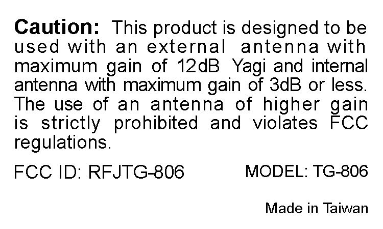
American Telecommunications Certification Body Inc. 6731 Whittier Ave, McLean, VA 22101 October 7, 2003 RE: FCC ID: RFJTG-806_ATCB000766 Attention: Leon Kass I have a few comments on this Application. 1. The second photo in the exhibit, I assume, is the bottom of the board. However, the photo is not clear. Please provide clear photos of both sides of all boards. The photos should be of the quality that a full view of all components can be easily seen. 2. Please note that the antenna connection point for duplexer DUP2 is only assumed to be at pin 1. However, this connection is not made clear in the schematics. Please verify this connector location. x 3. Please provide a theory of operation for the device. 4. Please note that the label states that the external antenna cannot exceed 3dBd gain. Please explain if this is speaking of the indoor antenna gain or of both the indoor and outdoor antenna gains. 5. Please note that the label on the device states that an external antenna of no greater than 3dBd (5.12 dBi) gain can be used. In the manual you state that in poor reception area the use of a YAGI antenna be used. The gain of a YAGI is dependent on the number of elements and can exceed 18dBd (20dBi) gain. Please explain and/or correct all documentation as necessary to be in line with the label statement restricting us of antenna(s) with greater gain than 3dBd (5.12dBi). 6. The manual states max output of 21dBm. The report states 25dBm. Documentation should be consistent. Please explain. 7. Please note that since this is a licensed device, spurious emissions must be measured using antenna substitution methods as found in TIA 603. Your report only states that the device was placed on an OATS and radiated emissions measurements were made. Also, no radiated spurious emissions were provided as stated in the report. Please test the radiated emissions using the antenna substitution methods found in TIA603 as required by the FCC. 8. Please note that the 28dBm downlink power listed on page 1 of the report does not agree with the actual measured power of 29.1dBm listed on page 5 of the report. 9. Please note that on the frequency stability tabular data on page 7 of the report the first frequency line entry (806MHz) shows a frequency shift of 60MHz. While this may be a typographical error the data is in question. Please explain and correct as needed. 10. Please verify and or correct the table headings shown on page 8 of the report. 11. Please note that intermodulation products are considered to be spurious emissions by the FCC. As such they must meet the requirements of the associated emission mask for the rule part used. SMR part 90 device must meet the 43+10log(P) of 80dB (which ever is the lesser attenuation) for spurious emissions outside the assigned bands. This level is equal approximately -13dBm (either conducted or radiated (antenna substitution method). Please note that the intermod products shown in the plots in the files “Confidential_Test report-page8.pdf” and “Confidential_Test report- page10.pdf” appears to fail. Please explain. 12. Please note that the output plot correlating to the input plot found on “Confidential_Test report- page14.pdf” does not appear to have been provided. Please explain. 13. Please provide more information on the input wave than just “sine wave” and “square wave”. Please note that amplifiers and amplifier repeaters should be tested using the type modulation they will be amplifying. This means input and comparative output plots should be done using FID, DXW modulations as indicated in the documentation. Please verify that the inputs selected (16kHz FM, etc) represent the FID, DXW input signals expected at the input of the device. This deals primarily z Page 2 October 7, 2003 with the square wave representing DXW modulation. Please explain how a 16kHz square wave accurately represent a DXW (TDMA) signal? 14. Please verify that the emissions designator DXW is the designator for the device. (I do not see how a TDMA SS modulation system can be adequately emulated by a simple square wave – whereas a simpler digital modulation type might be). Dennis Ward mailto:[email protected] The items indicated above must be submitted before processing can continue on the above referenced application. Failure to provide the requested information may result in application termination. Correspondence should be considered part of the permanent submission and may be viewed from the Internet after a Grant of Equipment Authorization is issued. Please do not respond to this correspondence using the email reply button. In order for your response to be processed expeditiously, you must submit your documents through the AmericanTCB.com website. Also, please note that partial responses increase processing time and should not be submitted. Any questions about the content of this correspondence should be directed to the sender.
Cover Letter(s)
American Telecommunications Certification Body Inc. 6731 Whittier Ave, McLean, VA 22101 March 13, 2004 RE: FCC ID: RFJTG-806_ATCB000766 Attention: Leon Paul Kass I have a few comments on this Application. A couple of questions did not seem to get answered and a couple of questions have come up as a result of the new report. First, the following items from the first ATCB comments still need to be addressed. These issues are: Item 3 The theory of operation has not been provided. Item 5 Please note that the label on the device states that an external antenna of no greater than 3dBd (5.12 dBi) gain can be used. In the manual you state that in poor reception area the use of a YAGI antenna be used. The gain of a YAGI is dependent on the number of elements and can exceed 18dBd (20dBi) gain. Please explain and/or correct all documentation as necessary to be in line with the label statement restricting us of antenna(s) with greater gain than 3dBd (5.12dBi). Second the issues with the new report 1 The new report states that this device is a part 22H. Please note that Part 22H is for the cell band frequency range of 824 to 849 and 869 to 894MHz. The report also states 22.901d. Please note that there is no rule part 22.901d as this particular section has been removed. 22.901 now only has a and b section and again only in the cell band frequency ranges. While Part 22 has frequencies in the Public Mobile Service at the ranges tested, the report must properly reflect these frequencies and rule parts. The testing on this device is 806 to 825MHa and 851 to 870MHz. The 731 also is for an application to only part 90. Please provide a test report that tests to and reports on the appropriate and proper rule parts. Please clearly state and identify the rule parts under which this device is seeking certification. 2 While a CW signal was used to measure the power output of the booster/amp, there is nothing in the report to suggest that the test was performed with the maximum input level. Please confirm that the testing of maximum output power was performed using the maximum input power. 3 Please note that the test report states that TIA603 section 2.2.1.1 paragraph 5 was used to test radiated spurious emissions. Please note that section 2.2.1.1 of TIA603 is the definition paragraph for conducted carrier output power test. Please note that 2.2.12.2 is the test method for radiated spurious emissions testing. Please re-test the device using the proper Radiated Spurious emissions test section of TIA603 section 2.2.12.2. Please also show the signal generator level, the substitution antenna value in dB and the cable fator (if used) in the measurement table. Please show the sample formula used as required by CFR47. 4 Please note that as this is a licensed device, part 15 has no meaning. Thus, conducted and radiated emissions IAW part 15B are not required. Please explain why part 15 conducted and radiated emissions has been performed (i.e. is this also a computer peripheral or digital device?). Alternately, as they are superfluous and unnecessary information, please remove the part 15 data from the licensed device report. 5 Please note that the test report states that F8W, F1D, DXW and F9W modulations are applicable to this booster/amplifier. The test report shows data for TDMA(DXW) and GSM(GXW), but does not provided test data for F9W(CDMA) or F1D (wideband data), F8W (Voice & SAT signal and signaling tone). Consequently, the report only shows z Page 2 March 13, 2004 compliance to one of the emissions designators listed (DXW) and one that is not listed (GXW). Please note that booster/amplifiers must show compliance with all modulation types that are to be used. Please provide test data on the device showing compliance to CDMA (F9W), Wideband data (F8W) and F1D modulations. Dennis Ward mailto:[email protected] The items indicated above must be submitted before processing can continue on the above referenced application. Failure to provide the requested information may result in application termination. Correspondence should be considered part of the permanent submission and may be viewed from the Internet after a Grant of Equipment Authorization is issued. Please do not respond to this correspondence using the email reply button. In order for your response to be processed expeditiously, you must submit your documents through the AmericanTCB.com website. Also, please note that partial responses increase processing time and should not be submitted. Any questions about the content of this correspondence should be directed to the sender.
Cover Letter(s)
From: Les Payne [mailto:[email protected]] Sent: Tuesday, March 23, 2004 2:06 PM To: dward ATCB Cc: Leon Kass Subject: RE: Revised Coiler TG-806 files Greetings Dennis, To answer the two items below. There was an error in the addition in the substitution formula. However, the difference in the readings would not be enough to cause the EUT to be out of spec. We will correct imbedded formulas for future reference. On item two, the occupied bandwidth plots are to show relative input and output signal characteristics and should not be used for indicating amplitude parameters. The input plots were taken with the signal in the bottom graticules of the spectrum analyzer (HP 8568) and are no longer acurate for amplitude measurements according to HP manuals. The true gain of the amplifier was measured at or near the reference level of the spectrum analyzer and then verified with a power meter for correlation. There is no internal limiting on this device. This should clear things up. Les -----Original Message----- From: dward ATCB [mailto:[email protected]] Sent: Wednesday, March 17, 2004 4:19 PM To: 'Leon Paul Kass' Subject: RE: Revised Coiler TG-806 files Hi Leon One final note. Since the numbers for radiated spurious emissions are 20dB below the limit, I am not going to make an issue of the test method. However, please note that I cannot determine from the explanation given in the report if the antenna substitution method was actually used even though it references TIA603. From the formula given and from the data shown, it appears to me that only a radiated field strength type measurement was made. Another item is that the antenna gain was subtracted to the reading when I believe it should be added. Antenna substitution is measuring the power at 3 meters from the EUT then replacing the EUT with a signal generator and a substitution antenna. The signal generator is then set to a power level delivered to the substitution antenna that coincides with that measured from the EUT. This level from the signal generator is then measured and the substitution antenna gain is added to this number. This then is the ERP of the radiated spurious emissions. Perhaps I am reading it wrong, but this does not appear to be what was done in the report. From: dward ATCB [mailto:[email protected]] Sent: Friday, March 19, 2004 11:57 AM To: '[email protected]' Cc: William Graff Subject: RE: Revised Coiler TG-806 files Hi Les Please look at page 65 of the report. Please also note double ridge guide horns typically have positive gains. I have never heard of a horn that has a negative dB gain. As these items generally have small beam widths and concentrate energy through this small beam width, their gains would be positive as all of the energy is focused in the beam. This increases the power delivered to the antenna terminal, not decrease it. This means that the 8.7dBi in the table should be added. This also means that the -51.61dBm reading in the table for ERP would be -51.61+ 8.7 or = -42.91 (the limit then is -29.91 not -47 as reported. The horn would increase the power not decrease as shown in the table. Please explain how the horn has a negative gain. This is unlikely. Also, there is nothing in the report that shows the signs of the antenna gain that would allow you to change the arithmetic function. In the report it appears that you have positive gain and that you subtracted this positive gain. Please correct the tables to show exactly what is going on. Please also be aware of the positive gain nature of a horn antenna. As mentioned, the device appears compliant, but the tables need to reflect what is going on. Please explain. From: Les Payne [mailto:[email protected]] Sent: Friday, March 19, 2004 10:54 AM To: dward ATCB Subject: RE: Revised Coiler TG-806 files Sorry for the confusion our antenna gain factor are a negative number we will correct correct in the future documentation to indicate that we are added a negative as opposed to subtracting a positive. In the end the numbers come out the same. 50+(-10) = 40 50-10=40 Sorry for the confusion, Les -----Original Message----- From: dward ATCB [mailto:[email protected]] Sent: Thursday, March 18, 2004 8:33 AM To: [email protected]; 'Leon Paul Kass' Subject: RE: Revised Coiler TG-806 files Hi Les Please note that because the + gain of the antenna increases the effective power, the antenna is always added to the signal generator reading, not subtracted. The power being measured is the ERP (effective radiated Power). This is the power that includes the antenna gain. By subtracting the gain you are incorrectly reducing the power estimated power and this is not correct. Please use the formula provided in TIA 603 for ERP measurements. Please note that this formula is Pd(dBm) = Pg(dBm) – cable loss (dB) + antenna gain (dB). Please note that the sign of the sign of the antenna gain itself will determine if the power is more or less than measured at the generator output. If for example the antenna gain is -1dB, then the formula would plus a minus number. This will account for the loss in power. But in ALL cases, the substitution gain is always ADDED. This means that in some of your radiated data the actual calculated ERP is up to 16dB greater than reported. Please follow the antenna substitution formula and test methods described in TIA 603 section 2.2.12.2. Thanks Dennis From: Les Payne [mailto:[email protected]] Sent: Thursday, March 18, 2004 7:40 AM To: dward ATCB; 'Leon Paul Kass' Subject: RE: Revised Coiler TG-806 files Greetings Dennis, Just to confirm that the substitution method was performed here is the step by step procedure that we use at DNB. 1, Set up EUT on a 3 meter OATS. 2, Rotate table 360 degrees to determine maxima 3, Raise and lower antenna 1-4 meters to obtain maxima 4, Once maximum emission has been identified and recorded the unit is replaced with either a dipole (30-1000MHz) or a double ridge guide (above 1GHz) antenna 5, A signal generator i…
Text truncated - open the document above for the full version.
Operational Description
Operational description 1. The equipment is designed to efficiently improve weak RF signal in the area. 2. The Signal source will directly affect the efficiency of the indoor service range, so that you should use caution on the location of setting up the outdoor antennas. 3. The equipment is a two-way signal amplifier that requires (outdoor antenna) attention to the isolation between the input and output to avoid the interference. While setting up, please widen the distance between the indoor and outdoor antennas. (At least 70dB isolation) 4. The equipment is gain adjustable for uplink/downlink and the end-user can adjust the unit for the best condition. 5. The antenna lead from the outside antenna signal should be connected on the inside to the input side of the equipment. The outdoor signal level should keep at least on -80dBm, and never exceed +15dBm. 6. Making the Link budget before setting up (Note 1) 7. For iDEN system, choose 8D or RG8U, 50OHM; cable or better for low loss. Note 1: Link budget means deducting the return lose of cable, connector, and splitter, if used, from outdoor antenna as well as add the gain of repeater and antenna referred to as the indoor service range. This can be the estimation of service range before construction. If the link budget data is negative, place a pre-amplifier, higher powered antenna, lower loss cable.
RF Exposure Info
RF Exposure – MPE Calculations Within Building Input Transmitter Power: 160 mW Antenna Gain: 3 dB Cable loss: 2 dB @ 806– 830 MHz 2 dB @ 851 – 870 MHz Frequency range: 806-830 MHz and 851-870 MHz Assumptions 1. A single ¼ wavelength radiating antenna is assumed. 2. Closest exposure distance is assumed to be 20 cm Roof Mount Input Transmitter Power: 160 mW Antenna Gain: 12 dB Cable loss: 2 dB @ 806– 830 MHz 2 dB @ 851 – 870 MHz Frequency range: 806-830 MHz and 851-870 MHz Assumptions 1. A single ¼ wavelength radiating antenna is assumed. 2. Closest exposure distance is assumed to be 20 cm RF Exposure – MPE Calculations Calculations The following results shall be assumed to be accurate for the far-field only. These predictions will over-estimate power density in the near–field. Based on the use of a ¼ wavelength radiator, a distance of 20 cm is considered to be in the far-field for all cases. S = PG/4*PI*R 2 Within Building @ 806 – 830 MHz P is 160 mW G is 3 dB (Antenna gain – loss) or 10 (2/20) or 1.25 R is 20 cm S = 0.045 mW/cm 2 For Occupational/Controlled Exposure From 300 to 1500 MHz, power density limit is f/300 mW/cm 2 @ 806 MHz, power density limit is 2.69 mW/cm 2 For General Population/Uncontrolled Exposure From 300 to 1500 MHz, power density limit is f/1500 mW/cm 2 @ 806 MHz, Power density limit is 0.54 mW/cm 2 Conclusion: Meets MPE limits @ 851 – 870 MHz P is 160 mW G is 3 dB (Antenna gain – loss) or 10 (1/20) or 1.12 R is 20 cm S = 0.045 mW/cm 2 For Occupational/Controlled Exposure From 1,500 to 100,000 MHz, power density limit is 5 mW/cm 2 for 6 minutes. For General Population/Uncontrolled Exposure From 1,500 to 100,000 MHz, power density limit is 1 mW/cm 2 for 30 minutes. Conclusion: Meets MPE limits Roof Mount @ 806 – 830 MHz P is 160 mW G is 12 dB (Antenna gain – loss) or 10 (2/20) or 1.25 R is 20 cm S = 0.1.27 mW/cm 2 For Occupational/Controlled Exposure From 300 to 1500 MHz, power density limit is f/300 mW/cm 2 @ 806 MHz, power density limit is 2.84 mW/cm 2 For General Population/Uncontrolled Exposure From 300 to 1500 MHz, power density limit is f/1500 mW/cm 2 @ 806 MHz, Power density limit is 0.57 mW/cm 2 Conclusion: Meets MPE limits @ 851 – 870 MHz P is 160 mW G is 12 dB (Antenna gain – loss) or 10 (1/20) or 1.12 R is 20 cm S = 0.127 mW/cm 2 For Occupational/Controlled Exposure From 1,500 to 100,000 MHz, power density limit is 5 mW/cm 2 for 6 minutes. For General Population/Uncontrolled Exposure From 1,500 to 100,000 MHz, power density limit is 1 mW/cm 2 for 30 minutes. Conclusion: Meets MPE limits
Test Report
FCC ID: RFJTG-806 1 Application for Certification For an RF Amplifier Taiwan Coiler International Corp. 8F-4, No.75, Sec. 1, Hsin Tai Wu Road Taipei Hsian Taiwan RF Amplifier Part # TG-806 FCC ID: RFJTG-806 REPORT # RV48068A-004 This report was prepared in accordance with the requirements of the FCC Rules and Regulations Part 2, Subpart J, 2.1031 through 2.1057, and Part 90 and other applicable sections of the rules as indicated herein. Prepared By: Kevin Meyers DNB Engineering, Inc. 5969 Robinson Avenue Riverside, Ca 92503-8620 16 March 2004 FCC ID: RFJTG-806 2 TEST LAB PERSONNEL Test Performed by: Date Signature Thomas Elders 16 March 2004 APPROVALS Management Approval Date Signature Les Payne Sr. Engineering Manager 16 March 2004 Original report RV48068A-001 Dated 08 Dec 2003 Revised report RV48068A-002 Dated 02 Mar 2004 Revised report RV48068A-003 Dated 10 Mar 2004 Revised report RV48068A-004 Dated 16 Mar 2004 FCC ID: RFJTG-806 3 TABLE OF CONTENTS Section Title Sheet # Test Lab Personnel and Approvals 2 Table of Contents 3 Table of Figures 4 1.0 ADMINISTRATIVE DATA 5 1.1 Certifications and Qualifications 5 1.2 Measurements and Repeatability Information 5 1.3 Test Methodology 6 1.4 Test Equipment 6 1.5 Deviations 6 1.6 Test Description 7 Note: Paragraph numbers in this report follow the application section numbers found in the FEDERAL COMMUNICATIONS COMMISSION Rules and Regulations, Part 2, Subpart J for Certification of electronic equipment. 2.1033 (C) (1) Application for Certification 8 2.1033 (C) (2) FCC Identifier 9 2.1033 (C) (3) Installation and Operating Instructions (Service manual) 9 2.1033 (C) (4) Type of Emissions 9 2.1033 (C) (5) Frequency Range 9 2.1033 (C) (6) Operating Power 9 2.1033 (C) (7) Maximum Power Allowed in Applicable part(s) of the Rules 9 2.1033 (C) (8) Final RF Amplifier Input Power Characteristics 9 2.1033 (C) (9) Tune Up Procedure 9 2.1033 (C) (10) Schematic Diagram and Circuit Description 10 2.1033 (C) (11) Equipment Identification Plate 10 2.1033 (C) (12) Equipment Photographs (Internal) 10 2.1033 (C) (12) Equipment Photographs (External) 10 2.1033 (C) (13) Digital Modulation Techniques 10 2.1033 (C) (14) Test Data 10 Test Set-Up 11-12 2.1046 Measurement of RF Power Output 13-19 2.1049 Measurement of Occupied Bandwidth 20-56 2.1051 Spurious Emissions at Antenna Terminals 57-63 2.1053 Measurement of Field Strength of Spurious Radiation 64-70 2.1055 Measurement of Frequency Stability 71 2.1057 Frequency Spectrum to be Investigated 72 RF Exposure 73-75 Appendix A Photographs 76-78 FCC ID: RFJTG-806 4 TABLE OF FIGURES Section Sheet # Title FIGURE 1: TEST EQUIPMENT..........................................................................................................................................6 FIGURE 2: TEST RESULT SUMMARY............................................................................................................................10 FIGURE 3: TEST SET UP BLOCK DIAGRAM FOR RF POWER OUTPUT, EMISSIONS LIMITATIONS GSM/TDMA, OCCUPIED BANDWIDTH GSM/TDMA, CONDUCTED SPURIOUS EMISSIONS AT ANTENNA TERMINALS...............12 FIGURE 4: TEST SET UP BLOCK DIAGRAM FOR RADIATED EMISSIONS........................................................................12 FIGURE 5: OUTPUT POWER PLOTS, UPLINK.................................................................................................................14 FIGURE 6: OUTPUT POWER PLOTS, DOWNLINK...........................................................................................................17 FIGURE 7: OCCUPIED BANDWIDTH, TDMA DOWNLINK.............................................................................................21 FIGURE 8: OCCUPIED BANDWIDTH, GSM DOWNLINK...............…
Text truncated - open the document above for the full version.
Contact Information
Applicant
Andy Chen(Overseas Sales Manager/Director)
Technical Contact
Leon Kass, LLC ConsultantLeon P Kass
[email protected]727-593-3100
9695 135th Street · Seminole, Florida · United States
Technical Specifications
| # | Rule Parts | Frequency Range | Power Output | Emission | Tolerance |
|---|---|---|---|---|---|
| 4 | 9 | 851 MHz - 866 MHz | 160.00 mW | GXW | Amp |
Other Applications from Taiwan Coiler International Corp.

RFJCB-127
May 03, 2004External Radio Frequency Power Amplifier
Equipment Class
AMP - Amplifier