RGB-44MDLC2-44 inch Midili
King of Fans, Inc.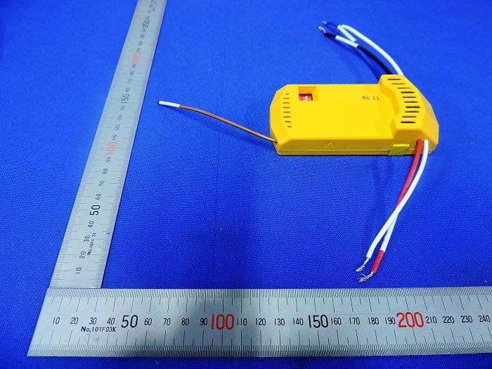
Click to zoom
Application Details
- Equipment Class
- CYY - Communications Receiver used w/Pt 15 Transmitter
- Date of Grant
- Jan 14, 2020
- Application Purpose
- Original Equipment
- Date of Application
- Jan 14, 2020
- Equipment Note
- 44 inch Midili
- Frequency Range
- 303.90000000 - 303.90000000
- Company
- King of Fans, Inc.
- Country
- USA Minor Outlying Islands
Documents & Files
Document Text
Text extracted from the exhibit documents filed with the FCC. Open a document above to read the original.
Users Manual
USE AND CARE GUIDE MIDILI 44 IN. CEILING FAN Questions, problems, missing parts? Before returning to the store call Hampton Bay Customer Service 8 a.m. - 7 p.m., EST, Monday-Friday, 9 a.m. - 6 p.m., EST, Saturday 1-855-HD-HAMPTON HAMPTONBAY.COM THANK YOU We appreciate the trust and confidence you have placed in Hampton Bay through the purchase of this ceiling fan. We strive to continually create quality products designed to enhance your home. Visit us online to see our full line of products available for your home improvement needs. Thank you for choosing Hampton Bay! To view an instructional video on how to install this product: 1. Go to www.homedepot.com and enter either the Item or Model number, found in the top right corner of the cover of this instruction manual, in the search eld. 2. Click on your product from the list of search results and click on the video link in the “Product Overview” section. Item #1002 711 156, 1002 711 135 Model #91100, 91044 UL Model #44-MDL The fan must be mounted with a minimum of 7 ft (2.1 m) clearance 2 Table of Contents ................................................................2 Safety Information ...............................................................2 Warranty ...............................................................................3 Pre-Installation ....................................................................3 Installation ............................................................................6 Assembly ..............................................................................7 Operation ...........................................................................15 Care and Cleaning .............................................................16 Troubleshooting .................................................................16 1. To reduce the risk of electric shock, ensure the electricity has been turned off at the circuit breaker or fuse box before you begin. 2. All wiring must be in accordance with the National Electrical Code ANSI/NFPA 70-1999 and local electrical codes. Electrical installation should be performed by a qualified licensed electrician. 3. The outlet box and support structure must be securely mounted and capable of reliably supporting 35 lbs. (15.9 kg). Use only UL Listed outlet boxes marked “Acceptable for Fan Support of 35 lbs. (15.9 kg) or less.” 4. from the trailing edge of the blades to the floor. 5. Do not operate the reversing switch while the fan blades are in motion. You must turn the fan off and stop the blades before you reverse the blade direction. 6. Do not place objects in the path of the blades. 7. To avoid personal injury or damage to the fan and other items, use caution when working around or cleaning the fan. 8. Electrical diagrams are for reference only. Light kits that are not packed with the fan must be UL-listed and marked suitable for use with the model fan you are installing. Switches must be UL General Use Switches. Refer to the instructions packaged with the light kits and switches for proper assembly. 9. After making electrical connections, spliced conductors should be turned upward and pushed carefully up into the outlet box. The wires should be spread apart with the grounded conductor and the equipment-grounding conductor on one side of the outlet box. 10. All setscrews must be checked and retightened where necessary before installation. WARNING: To reduce the risk of personal injury, do not bend the blade brackets (also referred to as flanges) during assembly or after installation. Do not insert objects in the path of the blades. WARNING: Remove the rubber motor stops on the bottom of the fan before installing the blades or testing the motor. WARNING: To reduce the risk of fire or electric shock, do not use this fan with any solid-state speed control device. WARNING: To avoid possible electrical shock, turn the electricity off at the main fuse box before wiring. If you feel you do not have enough electrical wiring knowledge or experience, contact a licensed electrician. WARNING: Electrical diagrams are for reference only. Optional use of any light kit shall be UL-listed and marked suitable for use with this fan. Safety Information Table of Contents WARNING: To reduce the risk of fire, electric shock or personal injury, mount to outlet box marked “Acceptable for fan support of 35 lbs. (15.9 Kg) or less,” and use screws provided with the outlet box. This equipment has been tested and found to comply with the limits for a Class B digital device, pursuant to Part 15 of the FCC Rules. These limits are designed to provide reasonable protection against harmful interference in a residential installation. This equipment generates, uses and can radiate radio frequency energy and, if not installed and used in accordance with the instructions, may cause harmful interference to radio communications. However, there is no guarantee that interference will not occur in a particular installation. If this equipment does cause harmful interference to radio or television reception, which can be determined by turning the equipment off and on, the user is encouraged to try to correct the interference by one or more of the following measures: --Reorient or relocate the receiving antenna. --Increase the separation between the equipment and receiver. --Connect the equipment into an outlet on a circuit different from that to which the receiver is connected. --Consult the dealer or an experienced radio/TV technician for help. CAUTION: Any changes or modifications not expressly approved by the grantee of this device could void the user’s authority to operate the equipment. This device complies with Part 15 of the FCC Rules. Operation is subject to the following two conditions: (1) This device may not cause harmful interference, and (2) this device must accept any interference received, including interference that may cause undesired operation. WARNING: To reduce the risk of fire or electric s…
Text truncated - open the document above for the full version.
Users Manual
4 PiezaDescripciónCantidad AAConector plástico para cables3 BBPasador de soporte1 CCPasador de cierre1 DDTornillos para montaje de aspas16 PiezaDescripciónCantidad EEHerrajes para montaje de aspas (tornillo y arandela de seguridad) 11 Preinstalación (continuación) HERRAJES INCLUIDOS NOTA: No se muestra el tamaño real de los herrajes. AABBCC DD EE 5 HAMPTONBAY.COM Para obtener asistencia, llama al 1-855-HD-HAMPTON. PiezaDescripciónCantidad ASoporte de montaje deslizante (dentro de la cubierta) 1 BEnsamblaje de tubo bajante/bola1 CCubierta con anillo de cubierta incorporado1 DCubierta decorativa del collarín del motor1 EEnsamblaje del motor del ventilador1 PiezaDescripciónCantidad FAspa5 GSoporte de aspa 5 HEnsamblaje del soporte del kit de luces 1 IPantalla de vidrio1 JReceptor1 KControl remoto1 LBombilla LED (máximo 9 watts)1 IMPORTANTE: Este producto y/o sus componentes están protegidos por una o más de las siguientes patentes de E.E.U.U.: 5,947,436; 5,988,580; 6,010,110; 6,046,416, 6,210,117 y otras patentes pendientes. Preinstalación (continuación) CONTENIDO DEL PAQUETE A B C F D I E J G H K L LIGHT/DIMMER GRADATEUR LUM LO BAS MED MOY HI HAUT FAN OFF ARRET VENT 6 Instalación OPCIONES DE MONTAJE ADVERTENCIA: Para reducir el riesgo de incendio, descarga eléctrica o lesiones personales, instala en una caja eléctrica clasificada como “apropiada para sostener ventiladores de 15.9 kg o menos” y usa tornillos de montaje que vienen con la misma. Las cajas eléctricas utilizadas comúnmente para el soporte de lámparas pueden no servir como soporte de ventilador y tal vez deban reemplazarse. En caso de duda, consulta a un electricista calificado. Si tu ventilador de techo no tiene una caja de montaje aprobada por UL, instala una siguiendo las instrucciones a continuación: □Desconecta la energía retirando los fusibles o apagando los cortacircuitos. □Asegura la caja eléctrica directamente a la estructura de la edificación. Usa los sujetadores y materiales apropiados. La caja eléctrica y su soporte deben sostener completamente el peso en movimiento del ventilador (al menos 15.9 kg). No uses una caja eléctrica de plástico. Las ilustraciones a continuación muestran tres formas distintas de montar la caja eléctrica. Si la cubierta toca el tubo bajante, retira la cubierta inferior de la tapa decorativa y gira la cubierta 180º antes de fijarla a la placa de montaje. Para colgar tu ventilador donde ya haya una lámpara pero ninguna viga de techo, tal vez necesites una barra colgante como se mostró anteriormente (disponible en cualquier tienda de The Home Depot). NOTA: Tal vez necesites un tubo bajante más largo para mantener la altura mínima adecuada de las aspas, al instalar el ventilador en un techo inclinado. El ángulo máximo permitido es de 30º con respecto a la posición horizontal. Caja eléctrica Caja eléctrica Caja eléctrica empotrada Soporte fuerte Placa de montaje en techo Caja eléctrica Barra para colgar 7 HAMPTONBAY.COM Para obtener asistencia, llama al 1-855-HD-HAMPTON. Ensamblaje - Montaje estándar en techo Disposición de los cables Cómo ensamblar el ventilador Preparación para el montaje □Afloja, sin quitar, el tornillo de fijación (II) del collarín (O) ubicado en la parte superior del ensamblaje del motor del ventilador (E). □Alinea los orificios en la parte inferior del tubo bajante (B) con los orificios en el collarín (O) de la parte superior del ensamblaje del motor del ventilador (E). □Inserta con cuidado el pasador de soporte (BB) a través de los orificios del collarín (O) y del tubo bajante (B). Ten cuidado de no forzar el pasador de soporte (BB) contra el cableado dentro del tubo bajante (B). □Inserta el pasador de cierre (CC) en el orificio cercano al extremo del pasador de soporte (BB) hasta que quede encajado en su posición. □Aprieta nuevamente el tornillo de fijación (II) del collarín (O) ubicado en la parte superior del ensamblaje del motor del ventilador (E). □Retira el aro de cubierta (M) de la cubierta (C), girándolo en sentido contrario a las manecillas del reloj hasta soltarlo. □Retira el soporte de montaje (A) de la cubierta (C) aflojando los dos tornillos de la cubierta (GG) ubicados en las ranuras en forma de “L”. □Quita y guarda los dos tornillos de la cubierta (HH) en los orificios redondos. Esto te permitirá retirar el soporte de montaje (A). □Inserta los cables que salen por la parte superior del ensamblaje del motor del ventilador (E) a través del centro del anillo de la cubierta (M). Asegúrate de que las ranuras del anillo de la cubierta (M) estén en la parte superior. □Inserta el tubo bajante/bola (B) a través de la cubierta (C) y desliza la cubierta decorativa del collarín del motor (D) en el extremo del tubo bajante/bola (B). Asegúrate de que las ranuras de la cubierta (C) estén en la parte superior. □Inserta los cables que salen por la parte superior del ensamblaje del motor del ventilador (E) a través del tubo bajante (B) como se muestra. 2 3 1 C A M HH GG E D C B M E D C BB CC O II B ADVERTENCIA: Si no instalas correctamente el pasador de cierre es posible que el ventilador se afloje y caiga. 8 Ensamblaje - Cómo colgar el ventilador Cómo instalar el soporte de montaje en la caja eléctrica Cómo colgar el ventilador □Afloja los dos tornillos de montaje (1) de la caja eléctrica. □Pasa los cables de suministro de 120 voltios a través del orificio central en el soporte de montaje (A). □Desliza el soporte de montaje (A) en los tornillos de montaje (1) y centra el soporte (A) en relación con la caja eléctrica. Si es necesario, usa arandelas niveladoras (no se incluyen) entre el soporte de montaje deslizante (A) y la caja eléctrica. El lado plano del soporte de montaje deslizante (A) debe estar hacia la caja eléctrica, como se muestra. □Aprieta bien los dos tornillos de montaje (1). □Con cuidado levanta el ensamblaje del motor del ventilador (E) hasta el soporte de montaje deslizante (A). □Inserta la bola de soporte del ensamblaje del tubo bajante/ bola en el casquillo…
Text truncated - open the document above for the full version.
Cover Letter(s)
January 13, 2020 Federal Communications Commission Authorization & Evaluation Division 7345 Oakland Mills Road Columbia, Maryland 21046 Authority to Act as Agent On our behalf, I appoint Shenzhen Timeway Testing Laboratories/ 5/F,Block 4, Anhua Industrial Zone.,No.8 TaiRan Rd.CheGongMiao,FuTian District, Shenzhen,CHINA. (Name of Agent company name and address) to act as our agent in the preparation of this application for equipment certification. I certify that submitted documents properly describe the device or system for which equipment certification is sought. I also certify that each unit manufactured, imported or marketed, as defined in the Federal Communications Commission’s regulations will have affixed to it a label identical to that submitted for approval with this application. For instances where our authorized agent signs the application for certification on our behalf, I acknowledge that all responsibility for complying with the terms and conditions for certification, still resides with King of Fans, Inc./ 1951 N.W. 22nd Street, Fort Lauderdale, FL33311, USA <Signature>: Name:Charles Bucher Title:Manager Applicant Company:King of Fans, Inc.
Cover Letter(s)
January 13, 2020 Equipment Autorisation Division Federal Communications Commission 7435 Oakland Mills Road Columbia, MD 21046 FCC ID: RGB-44MDLC2- Product Name: 44 inch Midili Request for Confidentiality Pursuant to Sections 0.457 and 0.459 of the commissions rules, we hereby request that the following documents be held confidential: Schematics Block diagram Operation description These materials contain trade secrets and proprietary information and are not customarily released to the public. The public disclosure of this information might be harmful to the company and provide unjustified benefits to our competitors. <Signature>: Name:Charles Bucher Title:Manager Company:King of Fans, Inc.
ID Label/Location Info
Label Location
ID Label/Location Info
. R O O L F O T S E D A L B K S I R E C U D E R O T : - T N I A M , S N O S R E P O T Y R U J N I F O NO: I . M S . P O U R G T A N I N W T : O T L H L I S O F P R E O H D T U F C O T E A R N O D / O M R R C O O E M N P O O Y N B E N D T S E R E A R E C O V P . A G T N E I N D T N S E : P 5 , 9 S 4 T 7 , N 4 3 E 6 T ; A 5 P , 9 8 R 8 E , 5 H 8 0 T ; O 5 , D 9 7 N 1 , 5 A 7 6 3 1 ; , 4 6 6 , 0 4 1 , 0 0 6 , 1 ; 1 0 1 ; 6 , 5 4 , 0 1 , 0 3 9 0 , 3 0 6 ; 6 I M S P E O T R N T E A T N A T P E E : T E S N T E E N P G I R S O S D O U L C T E O D Y O / N O U L O R S O C P O O M D P I E O R N B E N U T E N C S EST A A M E R I C A N O S : 5 , 9 4 7 , 4 3 6 ; 5 , 9 8 8 , 5 8 0 ; 5 , 9 7 1 , 5 7 3 ; 6 , 0 1 0 , 1 1 0 ; 6 , 0 1 0 , 3 0 6 ; E T N E I D N E P S E T N E T A P S O R T O Y ; 6 1 4 , 6 4 0 , 6 ; 1 4 , 5 9 3 , 0 6 U P C # 0 8 2 3 9 2 9 1 1 0 0 3 2 - F C C I D : R G B - 4 4 M D L C This device complies with part 15 of the FCC rules. Operation is subject to the following two conditions (1) this device may not cause harmful interference, and (2) this device must accept any interference received, including interference that may cause undesired operation.
Test Report
Report No.: FCC2001052 File reference No.: 2020-01-08 Applicant: King of Fans, Inc. Product: 44“ Midili Model No: 44-MDL Trademark: Hampton Bay Test Standards: FCC Part 15 Subpart B Test result: It is herewith confirmed and found to comply with the requirements set up by ANSI C63.4&FCC Part 15 regulations for the evaluation of electromagnetic compatibility Approved By Jack Chung Manager Dated: January 08, 2020 Results appearing herein relate only to the sample tested The technical reports is issued errors and omissions exempt and is subject to withdrawal at SHENZHEN TIMEWAY TESTING LABORATORIES Zone C, 1st Floor, Block B, Jun Xiang Da Building, Zhongshan Park Road West, Tong Le Village, Nanshan District, Shenzhen, China Tel (755) 83448688, Fax (755) 83442996, E-Mail:[email protected] Report No: FCC2001052 Page 2 of 31 Date: 2020-01-08 The report refers only to the sample tested and does not apply to the bulk. This report is issued in confidence to the client and it will be strictly treated as such by the SHENZHEN TIMEWAY TESTING LABORATORIES. It may not be reproduced rather in its entirety or in part and it may not be used for adverting. The client to whom the report is issued may, however, show or send it . or a certified copy there of prepared by the SHENZHEN TIMEWAY TESTING LABORATORIES. to his customer. Supplier or others persons directly concerned. SHENZHEN TIMEWAY TESTING LABORATORIES. will not, without the consent of the client enter into any discussion of correspondence with any third party concerning the contents of the report. In the event of the improper use of the report. The SHENZHEN TIMEWAY TESTING LABORATORIES. reserves the rights to withdraw it and to adopt any other remedies which may be appropriate. Special Statement: The testing quality ability of our laboratory meet with "Quality Law of People's Republic of China" Clause 19. The testing quality system of our laboratory meet with ISO/IEC-17025 requirements, which is approved by CNAS. This approval result is accepted by MRA of APLAC. Our test facility is recognized, certified, or accredited by the following organizations: CNAS-LAB Code: L2292 The EMC Laboratory has been assessed and in compliance with CNAS-CL01 accreditation criteria for testing Laboratories (identical to ISO/IEC 17025:2005 General Requirements) for the Competence of testing Laboratories. FCC-Registration No.: 744189 The EMC Laboratory has been registered and fully described in a report filed with the (FCC) Federal Communications commission. The acceptance letter from the FCC is maintained in our files. Registration No.: 744189. Industry Canada (IC) —Registration No.:5205A The EMC Laboratory has been registered by Certification and Engineering Bureau of Industry Canada for radio equipment testing with Registration No.: 5205A. A2LA (Certification Number:5013.01) The EMC Laboratory has been accredited by the American Association for Laboratory Accreditation (A2LA). Certification Number:5013.01 Report No: FCC2001052 Page 3 of 31 Date: 2020-01-08 The report refers only to the sample tested and does not apply to the bulk. This report is issued in confidence to the client and it will be strictly treated as such by the SHENZHEN TIMEWAY TESTING LABORATORIES. It may not be reproduced rather in its entirety or in part and it may not be used for adverting. The client to whom the report is issued may, however, show or send it . or a certified copy there of prepared by the SHENZHEN TIMEWAY TESTING LABORATORIES. to his customer. Supplier or others persons directly concerned. SHENZHEN TIMEWAY TESTING LABORATORIES. will not, without the consent of the client enter into any discussion of correspondence with any third party concerning the contents of the report. In the event of the improper use of the report. The SHENZHEN TIMEWAY TESTING LABORATORIES. reserves the rights to withdraw it and to adopt any other remedies which may be appropriate. Test Report Conclusion Content 1.0 General Details ................................................................................................ 4 1.1 Test Lab Details................................................................................................ 4 1.2 Applicant Details.............................................................................................. 4 1.3 Description of EUT ............................................................................................ 4 1.4 Test Uncertainty................................................................................................ 4 1.5 Submitted Sample............................................................................................. 4 1.6 Test Duration.................................................................................................. 4 2.0 List of Measurement Equipment........................................................................ 5 2.1 Conducted Emission Test..................................................................................... 5 2.2 Radiated electromagnetic disturbance test................................................................. 5 2.3 Auxiliary Equipment.......................................................................................... 5 3.0 Technical Details............................................................................................. 6 3.1 Investigations Requested..................................................................................... 6 3.2 Test Standards.................................................................................................. 6 4.0 Power line Conducted Emission Test..................................................................... 7 5.0 Radiated Disturbance Test................................................................................... 11 6.0 FCC Label ........................................................................................................... 18 7.0 Photo of testing................................…
Text truncated - open the document above for the full version.
Test Setup Photos
Conducted Emission Te s t Setup: Radiated Emission Te s t Setup:
Contact Information
Applicant
Charles Bucher
Test Firm
Shenzhen Timeway Testing LaboratoriesTerry Tang
[email protected]+86-755-83448688
Technical Specifications
| # | Rule Parts | Frequency Range | Power Output |
|---|---|---|---|
| 1 | 15B | 303.9 MHz - 303.9 MHz | - |
Other Applications from King of Fans, Inc.

RGB-MS412W
Feb 11, 2026Low Voltage smart transformer
Equipment Class
DTS - Digital Transmission System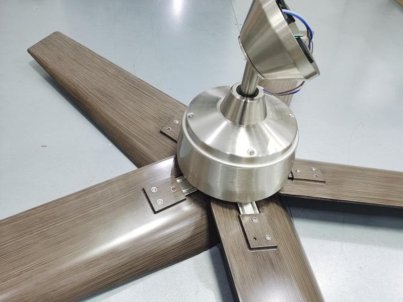
RGB-60-SHURIS
May 06, 202260in Feldner (was Shuri)
Equipment Class
CYY - Communications Receiver used w/Pt 15 Transmitter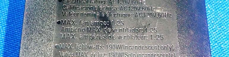
RGB-52BVDD
Nov 18, 202052 in Campbell, 91350/91359
Equipment Class
CYY - Communications Receiver used w/Pt 15 Transmitter
RGB-52JUNED
Nov 14, 202052 in Junedale (was Sarasota) 52188
Equipment Class
CYY - Communications Receiver used w/Pt 15 Transmitter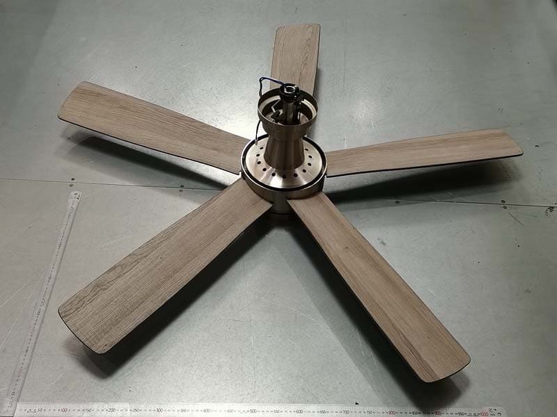
RGB-54FANES
Nov 02, 202054 Inch Fanelee 52133
Equipment Class
CYY - Communications Receiver used w/Pt 15 Transmitter