RGB-ADBTLK2855XUniversal Audio Light Kit with BLUETOOTH Technology
King of Fans, Inc.
Click to zoom
Application Details
- Equipment Class
- DSS - Part 15 Spread Spectrum Transmitter
- Date of Grant
- Mar 31, 2014
- Application Purpose
- Original Equipment
- Date of Application
- Mar 29, 2014
- Equipment Note
- Universal Audio Light Kit with BLUETOOTH Technology
- Frequency Range
- 2402.00000000 - 2480.00000000
- Company
- King of Fans, Inc.
- Country
- USA Minor Outlying Islands
Documents & Files
Document Text
Text extracted from the exhibit documents filed with the FCC. Open a document above to read the original.
Users Manual
Item #xxx-xxx Model #28556/28557/28558/28559 ETL Model #28556/28557/28558/28559 USE AND CARE GUIDE UNIVERSAL AUDIO LIGHT KIT WITH BLUETOOTH ® TECHNOLOGY Questions, problems, missing parts? Before returning to the store, call Hampton Bay Customer Service 8 a.m. - 6 p.m., EST, Monday-Friday. 1-855-HD-HAMPTON HAMPTONBAY.COM THANK YOU We appreciate the trust and confidence you have placed in Hampton Bay through the purchase of this light kit. We strive to continually create quality products designed to enhance your home. Visit us online to see our full line of products available for your home improvement needs. Thank you for choosing Hampton Bay! 2 Table of Contents ................................................................2 Safety Information ...............................................................2 Warranty ...............................................................................2 Safety Information Table of Contents Warranty CAUTION: All glass is fragile, use care when handling the glass bowl. CAUTION: To avoid accidental burning, allow the bulb and glass bowl to cool completely before touching or replacing the glass bowl or bulbs. CAUTION: To reduce the risk of electrical shock, before starting installation, disconnect the power by turning off the circuit breaker or removing the fuse at the fuse box. Turning the power off using the fan switch is not sufficient. The supplier warrants the light kit to be free from defects in workmanship and material present at time of shipment from the factory for one year after the date of purchase by the original purchaser. The supplier also warrants that all other light kit parts, excluding any glass, to be free from defects in workmanship and material at the time of shipment from the factory for a period of three years after the date of purchase by the original purchaser. We agree to correct such defects without charge or at our option replace with a comparable or superior model if the product is re- turned. To obtain warranty service, you must present a copy of the receipt as proof of purchase. All costs of removing and reinstalling the product are your responsibility. Damage to any part such as by accident, misuse, improper installation or by affixing any accessories, is not covered by this warranty. Because of varying climatic conditions this warranty does not cover any changes in brass finish, including rusting, pitting, corrod- ing, tarnishing, or peeling. Brass finishes of this type give their longest useful life when protected from varying weather conditions. Servicing per- formed by unauthorized persons shall render the warranty invalid. There is no other express warranty. Hampton Bay hereby disclaims any and all warranties, including but not limited to those of merchantability and fitness for a particular purpose to the extent permitted by law. The duration of any implied warranty which cannot be disclaimed is limited to the time period as specified in the express warranty. Some states do not allow a limitation on how long an implied warranty lasts, so the above limitation may not apply to you. The retailer shall not be liable for incidental, conse- quential, or special damages arising out of or in connection with product use or performance except as may otherwise be accorded by law. Some states do not allow the exclusion of incidental or consequential damages, so the above exclusion or limitation may not apply to you. This warranty gives specific legal rights, and you may also have other rights which vary from state to state. This warranty supersedes all prior warranties. Ship- ping costs for any return of product as part of a claim on the warranty must be paid by the customer. Contact the Customer Service Team at 1-855-HD-HAMPTON or visit www.hamptonbay.com. FCC ID: RGB-ADBTLK2855X This device complies with part 15 of the FCC rules. Operation is subject to the following two conditions (1) this device may not cause harmful interference, and (2) this device must accept any interference received, including interference that may cause undesired operation. Changes or modifications not expressly approved by the party responsible for compliance could void the user’s authority to operate the equipment. READ AND SAVE THESE INSTRUCTIONS. CAUTION: To reduce the risk of electrical shock, this light should be used only with the fan models listed below: WARNING: Changes or modifications to this unit not expressly approved by the party responsible for compliance could void the user’s authority to operate the equipment. Models: 728-046, 513-394, 513-708 Manufactured by company: Chein Luen Industries (Zhongshan) LTD Pre-Installation ....................................................................3 Installation ............................................................................4 CAUTION: To reduce the risk of electrical shock, The Universal Light Kit with Bluetooth® Technology suitable to be used in damp locations. 3 HAMPTONBAY.COM Please contact 1-855-HD-HAMPTON for further assistance. TOOLS REQUIRED Phillips screwdriver Electrical tape Wire cutter Step ladder PartDescriptionQuantity ALight kit fitter assembly1 BLight bulbs, 14W CFL’s2 CGlass bowl1 PACKAGE CONTENTS A C B Pre-Installation AA BB CC PartDescriptionQuantity AAHex nut1 BBLockwasher1 CCPull Chain2 HARDWARE INCLUDED Remove the center plug (DD) from the switch cup cover (E). 4 Preparing the light kit Wiring the light kit to the fan Preparing the fan □Locate the blue and white wires inside the ceiling fan switch cup (D) for light connection. □ Connect the blue wire form the ceiling fan switch cup to the black wire from the light kit (A). □Connect the white wire from the ceiling fan switch cup to the white wire from the light kit (A) by connecting the molded plugs together. □Reattach the switch cup cover (E) to the ceiling fan switch cup (D) and secure with the screws (EE) that were removed in step 1. □ Remove the ceiling fan switch cup cover (E) from the ceiling fan as…
Text truncated - open the document above for the full version.
Block Diagram
Block Diagram 电路方 电路方电路方 电路方框图 框图框图 框图
ID Label/Location Info
Label of Model: 28559 Label of Model: 28556 Label of Model: 28557 Label of Model: 28558
Operational Description
Technical Description电路 电路电路 电路原理 原理原理 原理描述 描述描述 描述 一、电源板 Power panel 1、电源AC100-240V供电 AC100-240V Power supply 2、D1、D2 D3、D4(1N4007)将 AC 桥式整流为 DC,输出到 T1(CS12F)开关变压器; D1, D2, D3, D4 (1 N4007) the AC rectify to DC, output to the T1 (CS12F) switch transformer; 3、U1(32E29A)通过脉冲控制 Q1(4N/600V)开关管进行高速道通与截止; U1 (32 e29a) control Q1 (4 n / 600 v) switch tube by pulse to high-speed channel and cut-off; 4、T1(CS12F)变压器输出的低压经 D8(SR5100)整流、滤波后输出 DC12V; T1 (CS12F) transformer output low voltage (8 (SR5100)), after rectifying and filtering, output DC12V; 二、功放板 Power amplifiers 1、电源DC12V供电; DC12V Power supply 2、U2(HT7136)将 12V 稳压为 3.6V,供给蓝牙模块工作电源; U2 (HT7136) stabilize 12 V to 3.6 V, provide work power to Bluetooth module; 3、U3(BM84)蓝牙模块接收到手机的音乐,通过解调输出到功放 U1(MAX98400A)输入端; Bluetooth module(U3 (BM84) ) receive cell phone music, through the demodulation output music to power amplifier U1 (MAX98400A) input terminal; 4、U1(MAX98400A)功放将音乐放大后,分左右声道输出到喇叭; After power amplifier U1 (MAX98400A) amplifying music, through left and right sound channel output to the speaker 5、蓝牙版本 3.0+EDR,采用 S 形 PCB 天线(50 ohm),工作频率为 2.4GHz(2402MHz - 2480MHz); Bluetooth version 3.0 + EDR use S-stype antenna (50 ohm), working frequency of 2.4 GHz (2402 MHZ to 2480 MHZ);
RF Exposure Info
Intertek Testing Services Shenzhen Ltd. Guangzhou Branch Job No.: 140128008GZU Page: 1 of 2 FCC ID: RGB-ADBTLK2855X RF Exposure Compliance Requirement 1. Standard requirement Systems operating under the provisions of this section shall be operated in a manner that ensures that the public is not exposed to radio frequency energy level in excess limit for maximum permissible exposure. In accordance with 47 CFR FCC Part 2 Subpart J, section 2.1091 this device has been defined as a mobile device whereby a distance of 0.2m normally can be maintained between the user and the device. (a) Limits for Occupational / Controlled Exposure Frequency Range (MHz) Electric Field Strength (E) (V/m) Magnetic Field Strength (H) (A/m) Power Density (S)(mW/cm 2 ) Averaging Times ׀E׀ 2 , ׀H׀ 2 or S (minutes) 0.3-3.0 614 1.63 (100)* 6 3.0-30 1842/f 4.89/f (900/f)* 6 30-300 61.4 0.163 1.0 6 300-1500 -- -- F/300 6 1500-100000 -- -- 5 6 (b) Limits for General Population / Uncontrolled Exposure Frequency Range (MHz) Electric Field Strength (E) (V/m) Magnetic Field Strength (H) (A/m) Power Density (S)(mW/cm 2 ) Averaging Times ׀E׀ 2 , ׀H׀ 2 or S (minutes) 0.3-1.34 614 1.63 (100)* 30 1.34-30 824/f 2.19/f (180/f)* 30 30-300 27.5 0.073 0.2 30 300-1500 -- -- F/1500 30 1500-100000 -- -- 1.0 30 Note: f=frequency in MHz; *Plane-wave equivalent power density Intertek Testing Services Shenzhen Ltd. Guangzhou Branch Job No.: 140128008GZU Page: 2 of 2 FCC ID: RGB-ADBTLK2855X 2. MPE Calculation Method E (V/m)=(30*P*G) 0.5 /d Power Density: Pd(W/m 2 )=E 2 /377 E=Electric Field (V/m) P=Peak RF output Power (W) G=EUT Antenna numeric gain (numeric) d= Separation distance between radiator and human body (m) The formula can be changed to Pd= (30*P*G)/(377*d 2 ) From the peak EUT RF output power, the minimum mobile separation distance, d=0.2m, as well as the gain of the used antenna, the RF power density can be obtained. 3. Calculated Result and Limit (1)Normal model(DH5): Frequency (MHz) Antenna Gain (Numeric) Peak Output Power (dBm) Peak Output Power (mW) Power Density (S) (mW/cm 2 ) Limit of Power Density (S) (mW/cm 2 ) Test Result 2402 2 1.61 1.45 0.0005 1 Complies 2441 2 1.71 1.48 0.0005 1 Complies 2480 2 1.60 1.45 0.0005 1 Complies (2) EDR mode(3DH5): Frequency (MHz) Antenna Gain (Numeric) Peak Output Power (dBm) Peak Output Power (mW) Power Density (S) (mW/cm 2 ) Limit of Power Density (S) (mW/cm 2 ) Test Result 2402 2 0.72 1.18 0.0004 1 Complies 2441 2 0.82 1.21 0.0004 1 Complies 2480 2 0.66 1.16 0.0004 1 Complies
Schematics
Power Schematics Control Schematics Bluetooth Schematics
Test Report
Report No.: 140128008GZU-001 Issued: 2014-3-18 FCC ID: RGB-ADBTLK2855X Page 2 of 65 CONTENT TEST REPORT...........................................................................................................................................................1 CONTENT...................................................................................................................................................................2 1.0 Summary of Test............................................................................................................................................3 2.0 General Description .......................................................................................................................................4 2.1 Product Description........................................................................................................................ 4 2.2 Related Submittal(s) Grants ........................................................................................................... 6 2.3 Test Methodology .......................................................................................................................... 6 2.4 Test Facility.................................................................................................................................... 6 3.0 System Test Configuration ............................................................................................................................7 3.1 Justification .................................................................................................................................... 7 3.2 EUT Information ............................................................................................................................ 8 3.3 Special Accessories ........................................................................................................................ 8 3.4 Measurement Uncertainty .............................................................................................................. 8 3.5 Equipment Modification................................................................................................................. 8 3.6 Support Equipment List and Description ....................................................................................... 8 4.0 Measurement Results.....................................................................................................................................9 4.1 Antenna Requirement..................................................................................................................... 9 4.2 20 dB Bandwidth.......................................................................................................................... 10 4.3 Carrier Frequencies Separated...................................................................................................... 14 4.4 Hopping Channel Number............................................................................................................ 19 4.5 Dwell Time................................................................................................................................... 21 4.6 Pseudorandom Frequency Hopping Sequence ............................................................................. 32 4.7 Maximum Peak Conducted Output Power ................................................................................... 33 4.5 Out of Band Conducted Emissions .............................................................................................. 38 4.6 Out of Band Radiated Emissions..................................................................................................44 4.7 Radiated Emissions in Restricted Bands ...................................................................................... 45 4.8 Band Edges Requirement ............................................................................................................. 57 4.9 Conducted Emission Test ............................................................................................................. 62 5.0 Test Equipment List.....................................................................................................................................65 Report No.: 140128008GZU-001 Issued: 2014-3-18 FCC ID: RGB-ADBTLK2855X Page 3 of 65 1.0 Summary of Test TEST TEST REQUIREMENT TEST METHOD RESULT Antenna Requirement FCC PART 15 C section 15.247 (c) and Section 15.203 FCC PART 15 C section 15.247 (c) and Section 15.203 PASS 20dB Bandwidth FCC PART 15 C section 15.247 (a)(1) ANSI C63.10: Clause 6.9.1 PASS Carrier Frequencies Separated FCC PART 15 C section 15.247(a)(1) ANSI C63.10: Clause 7.7.2 PASS Hopping Channel Number FCC PART 15 C section 15.247(a)(1)(iii) ANSI C63.10: Clause 7.7.3 PASS Dwell Time FCC PART 15 C section 15.247(a)(1)(iii) ANSI C63.10: Clause 7.7.4 PASS Pseudorandom Frequency Hopping Sequence FCC PART 15 C section 15.247(a)(1) ANSI C63.10: Clause 7.7.5 PASS Maximum Peak Conducted Output Power FCC PART 15 C section 15.247(b)(1) ANSI C63.10: Clause 6.10.1 PASS Out of Band Conducted Emissions FCC PART 15 C section 15.247(d) ANSI C63.10: Clause 6.7 PASS Out of Band Radiated Emission FCC PART 15 C section 15.247(d) ANSI C63.10: Clause 6.4, 6.5 and 6.6 PASS Radiated Emissions in Restricted Bands FCC PART 15 C section 15.209 &15.247(d) ANSI C63.10: Clause 6.4, 6.5 and 6.6 PASS Band Edges Measurement FCC PART 15 C section 15.247 (d) &15.205 ANSI C63.10: Clause 6.9.2 PASS Conducted Emissions at Mains Terminals FCC PART 15 C section 15.207 ANSI C63.10: Clause 6.2 PASS Remark: N/A: not applicable. Refer to the relative section for the details. EUT: In this whole report EUT means Equipment Under Test. Tx: In this whole report Tx (or tx) means Transmitter. Rx: In this whole report Rx (or rx) means Receiver. RF: In this whole report RF means Radio Frequency. ANSI C63.10: the detail version is A…
Text truncated - open the document above for the full version.
Contact Information
Applicant
Charles Bucher
Technical Contact
Intertek Testing Services Shenzhen Ltd.Guangzhou Bzhu Sky
[email protected]+86-20-82139691
Block E, No.7-2 Guang Dong Software Science Park, · Guangzhou · China
Test Firm
Intertek Testing Services Shenzhen Ltd.strong yao
[email protected]8628219940
Technical Specifications
| # | Rule Parts | Frequency Range | Power Output |
|---|---|---|---|
| 1 | 15C | 2.40 GHz - 2.48 GHz | 1.00 mW |
Other Applications from King of Fans, Inc.

RGB-MS412W
Feb 11, 2026Low Voltage smart transformer
Equipment Class
DTS - Digital Transmission System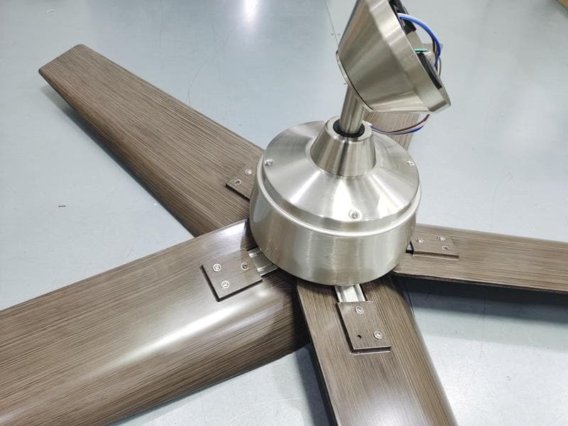
RGB-60-SHURIS
May 06, 202260in Feldner (was Shuri)
Equipment Class
CYY - Communications Receiver used w/Pt 15 Transmitter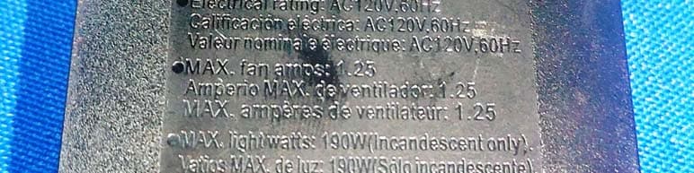
RGB-52BVDD
Nov 18, 202052 in Campbell, 91350/91359
Equipment Class
CYY - Communications Receiver used w/Pt 15 Transmitter
RGB-52JUNED
Nov 14, 202052 in Junedale (was Sarasota) 52188
Equipment Class
CYY - Communications Receiver used w/Pt 15 Transmitter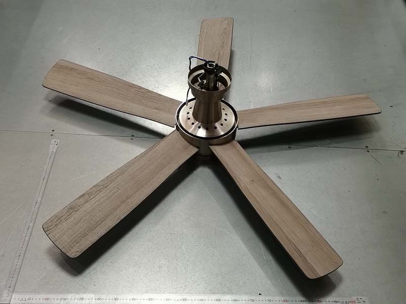
RGB-54FANES
Nov 02, 202054 Inch Fanelee 52133
Equipment Class
CYY - Communications Receiver used w/Pt 15 Transmitter