RH7DK310Digital Keypad
Sumec Machinery and Electric Manufacturing Co., Ltd.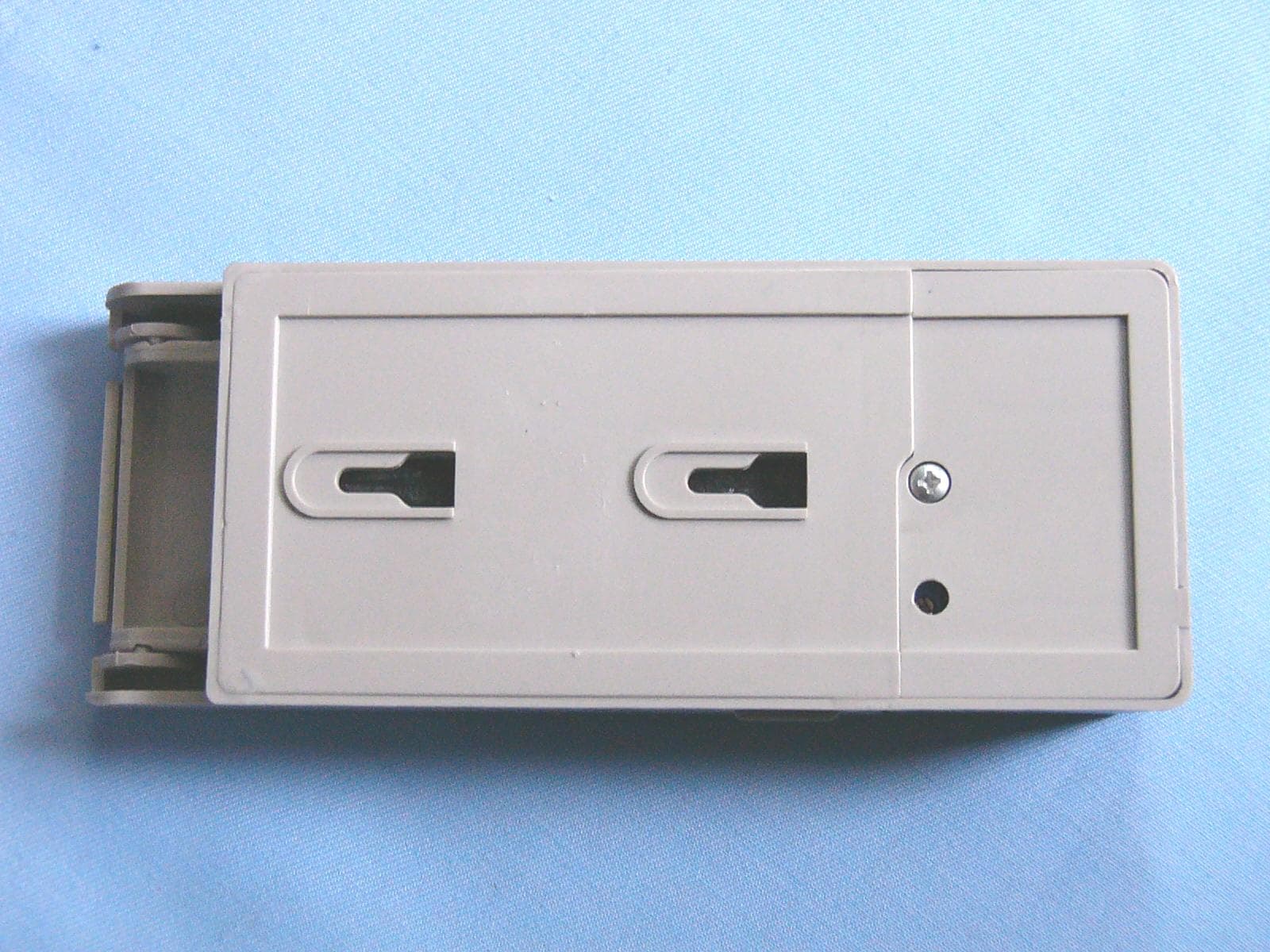
Click to zoom
Application Details
- Equipment Class
- DSC - Part 15 Security/Remote Control Transmitter
- Date of Grant
- Apr 01, 2004
- Application Purpose
- Original Equipment
- Date of Application
- Apr 01, 2004
- Equipment Note
- Digital Keypad
- Frequency Range
- 310.00000000 - 310.00000000
- Country
- China
Documents & Files
Document Text
Text extracted from the exhibit documents filed with the FCC. Open a document above to read the original.
Users Manual
1 Applicant: Sumec Machinery and Electric Manufacturing Co., Ltd. FCC ID: RH7DK310 Instruction Manual for Cipher Lock I Important message Note: The cipher lock can be only used in actuator of garage door which has rolling code technology and decode receiving machine inside. Safe cipher and transmitter (remote control) are set in cipher lock. Center frequency of the transmitter is 310MHz. The gate could cause hurt or death over persons when the gate is moving. ·If the reverse moving for safety of the garage door is not like what instruction of garage gate requires, you will not begin to have the remote control learned. ·Persons should stay away from the gate when the gate is moving. ·Never let children play with remote control or actuator. If reverse moving for safety of gate doesn’t work normally, ·Do not use remote control and garage gate actuator. ·Please refer to instruction of gate and gate actuator when trying to do repair. II Operation instruction 1. Input the administer cipher “123456”, ended by “ENTER”. If the cipher is correct, the background lamp flashes three times, waiting for inputting the operation cipher. 1) To modify the administer cipher as follows: (First input the administer cipher, ended by “ENTER”) Input operation cipher “11”, ended by “ENTER”, the background lamp flashes twice, and then input the new administer cipher (must be 6 digits), ended by “ENTER”, input the new administer cipher again (for second confirmation), and end it by “ENTER”. ·If the operation is correct, the background lamp flashes three times, indicating successful modification. Otherwise the background lamp flashes once, indicating failure of operation. 2) to add an individual user cipher, operate as follows: (First input the administer cipher, ended by “ENTER”) Input operation cipher “*”, and input the new user cipher (up to 6 digits), ended by “ENTER”, input the new user cipher again (for second confirmation), and ended by “ENTER”. ·If the operation is correct, the background lamp flashes twice, indicating successful cipher addition. Otherwise the background lamp flashes once, indicating failure of operation. 2 3) To delete an individual user cipher, operate as follows: (First input the administer cipher, ended by “ENTER”) Input operation cipher “#”, and input the user cipher (up to 6 digits), ended by “ENTER”, input the new user cipher again (for second confirmation), and end it by “ENTER”. ·If the operation is correct, the background lamp flashes twice, indicating successful cipher deletion. Otherwise the background lamp flashes once, indicating failure of operation. 4) To delete all user ciphers and reset administer cipher 123456, operate as follows: (First input the Administer cipher, ended by “ENTER”) Input operation cipher “#”, and input operation cipher “1*1*1”, ended by “ENTER”, input the operation cipher “1*1*1” again and end it by “ENTER”. ·If the operation is correct, the background lamp flashes four times, indicating successful cipher initialization. Otherwise the background lamp flashes once, indicating failure of operation. Note: After this operation, the original administer cipher will be initialized as 123456 no matter which the original administer cipher is, and all user’s ciphers will be deleted. The administer cipher must be entered first before any operation. After completion of one operation or a failure of operation, the administer cipher must be entered again if other operation are to be performed. 2. The user cipher can be used only for opening/closing the door, without administer function. The operation is as follows: Input the user cipher. If it is less than 6 digits, it should be ended by “ENTER”; if it is 6 digits, it is not necessary to have “ENTER” at the end. When the cipher is correct, the background lamp flashes twice, the cipher lock will transmit the signal automatically. You can press “*” to have another transmission within 20 seconds. 3 There is a terminal J1 for connecting wire in the battery box, it can also be used as a control with wire. Its operation is as follows: 1) When pin 2 of J1 (“TX”) is shorted with pin 3 (“+12V”), the cipher keyboard is for remote control transmission. There is no need to connect other pins of J1. 2) When Pin 2 of J1 (“TX”) is blank, the cipher keyboard is for wire control. In this case, Pin 1of J1 (“---“) is connected to ground G of main control board, Pin 3 is connected to +12V power supply of the main control board (ALARM)+, and Pin 4 (“WHT”) is connected to the terminal WHT of wire control on the main control board. 3 III learning remote control Different cipher lock has different code at the factory. Note: The receiving board can learn 5 remote control’s code, receiving system learns up to five remote controls’ code, shined diode flashes once then turns off; learning is invalid, withdrawing to ready state. Step 1: Check and ensure cipher lock is set well completely, and there is full of energy in the battery. Have the remote control pointed to the actuator of door garage. If cipher lock isn’t set completely, install the battery in the cipher lock. Step 2: Press learning button on receiving board, LED on receiving board flashes. Step 3:According to item 2, which introduce the user’s cipher function in section II, input user cipher, it will be transmitted automatically to the control board, the LED on control board will turn off after receiving the signal. Press “*” button for the second confirming (button “*” has transmiting function). When learning is successful. LED light flashes once (about one second), and buzzer will sound eight times, then turn off. (Remote control code is built in EMS memory of receiving system); Note: If remote control isn’t learned successful, the LED will flash once and buzzer will sound once for a long time. You can press “*” within 20 seconds for another learning process. - + J1 WHT - TX +12V - BLUWHTORGGRN WHT+12VTX J1 4 IV installation of battery Battery is installed and replaced as follows: Re…
Text truncated - open the document above for the full version.
External Photos
Applicant: Sumec Machinery and Electric Manufacturing Co., Ltd. FCC ID: RH7DK310 EUT top view EUT bottom view
ID Label/Location Info
Applicant: Sumec Machinery and Electric Manufacturing Co., Ltd. FCC ID: RH7DK310 Proposed Label Location on EUT EUT Bottom View/Proposed FCC ID Label Location FCC ID: RH7DK310
Internal Photos
Applicant: Sumec Machinery and Electric Manufacturing Co., Ltd. FCC ID: RH7DK310 EUT inside whole view Main board component side Main board solder side
Operational Description
Applicant: Sumec Machinery and Electric Manufacturing Co., Ltd. FCC ID: RH7DK310 Operational Description
Schematics
Applicant: Sumec Machinery and Electric Manufacturing Co., Ltd. FCC ID: RH7DK310
Test Report
The test report consists 25 pages in total. It may be duplicated completely for legal use with the allowance of the applicant. It shall not be reproduced except in full, without the written approval of Ke Mei Ou Laboratory Corporation. The test result in the report only applied to the tested sample. FCC TEST REPORT Under : FCC 15 Subpart C, Paragraph 15.231 Prepared For : Sumec Machinery and Electric Manufacturing Co., Ltd. Wei Er Road(W), New & Hi – Tehch, Deve, Dis, Nanjing P.R.China March 30, 2004 FCC ID: RH7DK310 EUT: Digital Keypad Model: DK310 Report Type: Original Report Test Engineer: Peter Lin Test Date: March 16, 2004 Review By: Apollo Liu / Manager FEDERAL COMMUNICATIONS COMMISSION Registration Number: 125782 INDUSTRY CANADA Registration Number: IC4986 Ke Mei Ou Laboratory Co., Ltd. 7A, Jiaxiangge, Jiahuixincheng, No.3027, Shennan Rd., Futian, Shenzhen, Guangdong, P.R.China. Zip Code: 518033 Tel: + 86 755 83642690 Fax: + 86 755 83297077 www.kmolab.com Sumec Machinery and Electric Manufacturing Co., Ltd. FCC ID: RH7DK310 KMO FCC ID Report Report #: KSZ2004030202J Page 2 of 25 TABLE OF CONTENTS 1. General Information...........................................................................................................................................................3 1. 1 Notes...............................................................................................................................................................................3 1. 2 Testing Laboratory..........................................................................................................................................................3 1. 3 Details of Applicant........................................................................................................................................................3 1. 4 Application Details.........................................................................................................................................................3 1. 5 Test Item.........................................................................................................................................................................3 1. 6 Test Standards.................................................................................................................................................................4 2. Technical Test.......................................................................................................................................................................5 2. 1 Summary of Test Results................................................................................................................................................5 3. EUT Modifications..............................................................................................................................................................6 4. Conducted Power Line Test................................................................................................................................................7 4. 1 Test Equipment...............................................................................................................................................................7 4. 2 Test Procedure................................................................................................................................................................7 4. 3 Test Setup.......................................................................................................................................................................7 4. 4 Configuration of The EUT..............................................................................................................................................8 4. 5 EUT Operating Condition...............................................................................................................................................9 4. 6 Conducted Power Line Emission Limits........................................................................................................................9 4. 7 Conducted Power Line Test Result...............................................................................................................................10 5. Radiated Emission Test......................................................................................................................................................11 5. 1 Test Equipment.............................................................................................................................................................11 5. 2 Test Procedure..............................................................................................................................................................11 5. 3 Radiated Test Setup......................................................................................................................................................11 5. 4 Configuration of The EUT............................................................................................................................................12 5. 5 EUT Operating Condition.............................................................................................................................................12 5. 6 Radiated Emission Limit..............................................................................................................................................12 5. 7 Radiated Emission Test Result......................................................................................................................................13 6. Technical Characteristic....................................................................................................................................................14 6. 1 Band Edge................................................................................…
Text truncated - open the document above for the full version.
Test Setup Photos
Applicant: Sumec Machinery and Electric Manufacturing Co., Ltd. FCC ID: RH7DK310 Radiated emission test view
Contact Information
Applicant
Guiqiang Luo Luo(Manager)
Test Firm
Ke Mei Ou Laboratory Co., Ltd.Apollo Liu
Technical Specifications
| # | Rule Parts | Frequency Range | Power Output |
|---|---|---|---|
| 1 | 15.231 | 310 MHz - 310 MHz | - |
Other Applications from Sumec Machinery and Electric Manufacturing Co., Ltd.
RH7DT310
Mar 22, 2004Door Transmitter
Equipment Class
DSC - Part 15 Security/Remote Control Transmitter
RH7-FP16
Oct 14, 2003Door Transmitter
Equipment Class
DSC - Part 15 Security/Remote Control Transmitter