RH7DT310Door Transmitter
Sumec Machinery and Electric Manufacturing Co., Ltd.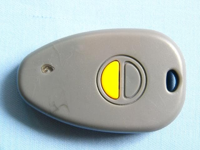
Click to zoom
Application Details
- Equipment Class
- DSC - Part 15 Security/Remote Control Transmitter
- Date of Grant
- Mar 22, 2004
- Application Purpose
- Original Equipment
- Date of Application
- Mar 22, 2004
- Equipment Note
- Door Transmitter
- Frequency Range
- 310.00000000 - 310.00000000
- Country
- China
Documents & Files
Document Text
Text extracted from the exhibit documents filed with the FCC. Open a document above to read the original.
Users Manual
Applicant: Sumec Machinery and Electric Manufacturing Co., Ltd. FCC ID: RH7DT310 TRANSMITTER INSTRUCTIONS 1. IMPORTANT INFORMATION NOTE:This transmitter only Use for intellicode Garage Door Openers that use scroll code technology. There are no security code switches inside the door Operators or Transmitters. The frequency of receiver is 310MHz, the receiver can receive radio signal from the Transmitter far from eighty meters in clear area. Moving Door can cause serious injury or death. ·DO NOT install transmitter unless the door operator’s safety reverse works as required by the door operators manual. ·Keep people clear of opening while door is moving. ·DO NOT allow children to play with the transmitter or door operator. If safety reverse does not work properly: ·Close door then disconnect operator using the manual release handle. ·DO NOT use transmitter or door operator. ·Refer to Door and Door Operator Owner’s Manuals before attempting any repairs. 2. TO PROGRAM THE RECEIVER A different Transmitter code is set at the factory for each Transmitter. Step 2-1:Check the Transmitter and the Transmitter battery powered, and then locate the Transmitter on the power head of your door operator. When press the Transmitter button, the light of the Transmitter should blink once. (fig 1) Step 2-2:Press and release the learn code button of receiver. The light (green) will lighten.(fig 2) Step 2-3:Press a Transmitter button over 1 second, the receiver radio signal indicator will go out. If the receiver has learned five transmitters, the receiver radio signal indicator will blink once and go out (the buzzer will ring eight times). Step 2-4:Press the same button of the Transmitter, the Radio Signal Indicator will blink once and go out (the Transmitter code is now stored in Receiver memory). NOTE: If a Transmitter code is not confirmed or if a different Transmitter code is sent, the receiver radio signal indicator will blink once and go out (the buzzer will ring one times), the programming will stop. If the programming stops, repeat previous steps. Step 2-5:Repeat previous steps for each Transmitter to be learned. NOTE: If a Transmitter becomes lost or if you want to delete a Transmitter, proceed to 4 ERASING ALL RECEIVER MEMORY and then reprogram the Receiver with the remaining Transmitters. P R O G 3. MULTI-BUTTON TRANSMITTERS NOTE:Only ONE button of a Multi-button Transmitter can be programmed into a single Receiver. The other buttons are to control other Door Operators. 4. ERASING ALL RECEIVER MEMORY Step 4-1:Press and hold the learn code button for 4 seconds or until Radio Signal Indicator goes out. All Transmitter Codes are erased from Receiver memory. Step 4-1:Reprogram the Receiver with the remaining Transmitter Codes (Repeat Step 2-2 through Step 2-4) 5. BATTERY INSTALLATION Step 5-1:Battery replacement (your Transmitter is battery powered) ·Remove the back of case.(fig 3) ·Install new battery in the same position. ·install the back of case. 6. TRANSMITTER OPERATON ·Point Transmitter at the garage door and press the button. Door will move. ·Press the Transmitter Button again and the door will stop. ·Press the Transmitter Button again and the door will move the other way. The door automatically stops at the end of open or close cycle. Federal Communications Commission (FCC ) Statement: This device complies with Part 15 of the FCC Rules. Operation is subject to the following two conditions: 1. This device may not cause interference, and 2. This device must accept any interference received, including interference that may cause undesired operation of the device. Note: The manufacturer is not responsible for any radio of TV interference caused by unauthorized modification to this euipment. Such modification could void the user’s authority to operate the euqipment.
Block Diagram
Applicant: Sumec Machinery and Electric Manufacturing Co., Ltd. FCC ID: RH7DT310
External Photos
Applicant: Sumec Machinery and Electric Manufacturing Co., Ltd. FCC ID: RH7DT310 EUT top view EUT bottom view
ID Label/Location Info
Applicant: Sumec Machinery and Electric Manufacturing Co., Ltd. FCC ID: RH7DT310 Proposed Label Location on EUT EUT Bottom View/Proposed FCC ID Label Location FCC ID: RH7DT310
Internal Photos
Applicant: Sumec Machinery and Electric Manufacturing Co., Ltd. FCC ID: RH7DT310 EUT inside whole view Main board component side Main board solder side
Operational Description
Applicant: Sumec Machinery and Electric Manufacturing Co., Ltd. FCC ID: RH7DT310 Operational Description 1) Description The RX310-01 is a low-power hand held remote control device operating at a frequency of 310MHz. The signal output is a binary-coded,32-bit hopping code generated by non-linear encryption algorithm, with a 28-bit serial number and six status bits .It utilizes hopping code which for high security and keyless entry(RKE) systems from Microchip Technology Inc. Actuating push buttons illuminates a light-emitting diode(LED) and activates the transmitter. Releasing the push-button immediately terminates transmission. Transmission time is limited to 30 seconds if button is held on 2) Functional Description The push-button switches,s1-3,applies power to the unit and activates L.E.D(D1) Digital encoding combines a 32-bit hopping code generated by a non-linear encryption algorithm, with a 28-bit serial number and six status bits to create a 66-bit transmission stream. The length of the transmission eliminates the threat of code scanning and the code hopping mechanism makes each transmission unique, thus rendering code capture and resend(code grabbing ) schemes useless. The RF oscillator functions as a high-frequency circuit which composed by T1,C4,C5, L1,L2 and the frequency of circuit is 310MHz, the signal is emitted by annular antenna L2. The frequency of oscillation is controlled by SAW resonator. T1is the RF output amplifier. Base bias capacitor C4&C5 regulates the power output of the oscillator.
Schematics
Applicant: Sumec Machinery and Electric Manufacturing Co., Ltd. FCC ID: RH7DT310
Test Report
The test report consists 25 pages in total. It may be duplicated completely for legal use with the allowance of the applicant. It shall not be reproduced except in full, without the written approval of Ke Mei Ou Laboratory Corporation. The test result in the report only applied to the tested sample. FCC TEST REPORT Under : FCC 15 Subpart C, Paragraph 15.231 Prepared For : Sumec Machinery and Electric Manufacturing Co., Ltd. Wei Er Road(W), New & Hi – Tehch, Deve, Dis, Nanjing P.R.China March 23, 2004 FCC ID: RH7DT310 EUT: Door Transmitter Model: FP16-12-54 Report Type: Original Report Test Engineer: Peter Lin Test Date: March 7, 2004 Review By: Apollo Liu / Manager FEDERAL COMMUNICATIONS COMMISSION Registration Number: 125782 Ke Mei Ou Laboratory Co., Ltd. 7A, Jiaxiangge, Jiahuixincheng, No.3027, Shennan Rd., Futian, Shenzhen, Guangdong, P.R.China. Zip Code: 518033 Tel: + 86 755 83642690 Fax: + 86 755 83297077 www.kmolab.com Sumec Machinery and Electric Manufacturing Co., Ltd. FCC ID: RH7DT310 KMO FCC ID Report Report #: KSZ2004010201J Page 2 of 25 TABLE OF CONTENTS 1. General Information...........................................................................................................................................................3 1. 1 Notes...............................................................................................................................................................................3 1. 2 Testing Laboratory..........................................................................................................................................................3 1. 3 Details of Applicant........................................................................................................................................................3 1. 4 Application Details.........................................................................................................................................................3 1. 5 Test Item.........................................................................................................................................................................3 1. 6 Test Standards.................................................................................................................................................................4 2. Technical Test.......................................................................................................................................................................5 2. 1 Summary of Test Results................................................................................................................................................5 3. EUT Modifications..............................................................................................................................................................6 4. Conducted Power Line Test................................................................................................................................................7 4. 1 Test Equipment...............................................................................................................................................................7 4. 2 Test Procedure................................................................................................................................................................7 4. 3 Test Setup.......................................................................................................................................................................7 4. 4 Configuration of The EUT..............................................................................................................................................8 4. 5 EUT Operating Condition...............................................................................................................................................9 4. 6 Conducted Power Line Emission Limits........................................................................................................................9 4. 7 Conducted Power Line Test Result...............................................................................................................................10 5. Radiated Emission Test......................................................................................................................................................11 5. 1 Test Equipment.............................................................................................................................................................11 5. 2 Test Procedure..............................................................................................................................................................11 5. 3 Radiated Test Setup......................................................................................................................................................11 5. 4 Configuration of The EUT............................................................................................................................................12 5. 5 EUT Operating Condition.............................................................................................................................................12 5. 6 Radiated Emission Limit..............................................................................................................................................12 5. 7 Radiated Emission Test Result......................................................................................................................................13 6. Technical Characteristic....................................................................................................................................................14 6. 1 Band Edge......................................................................................................................…
Text truncated - open the document above for the full version.
Test Setup Photos
Applicant: Sumec Machinery and Electric Manufacturing Co., Ltd. FCC ID: RH7DT310 Radiated emission test view
Contact Information
Applicant
Guiqiang Luo Luo(Manager)
Test Firm
Ke Mei Ou Laboratory Co., Ltd.Apollo Liu
Technical Specifications
| # | Rule Parts | Frequency Range | Power Output |
|---|---|---|---|
| 1 | 15.231 | 310 MHz - 310 MHz | - |
Other Applications from Sumec Machinery and Electric Manufacturing Co., Ltd.
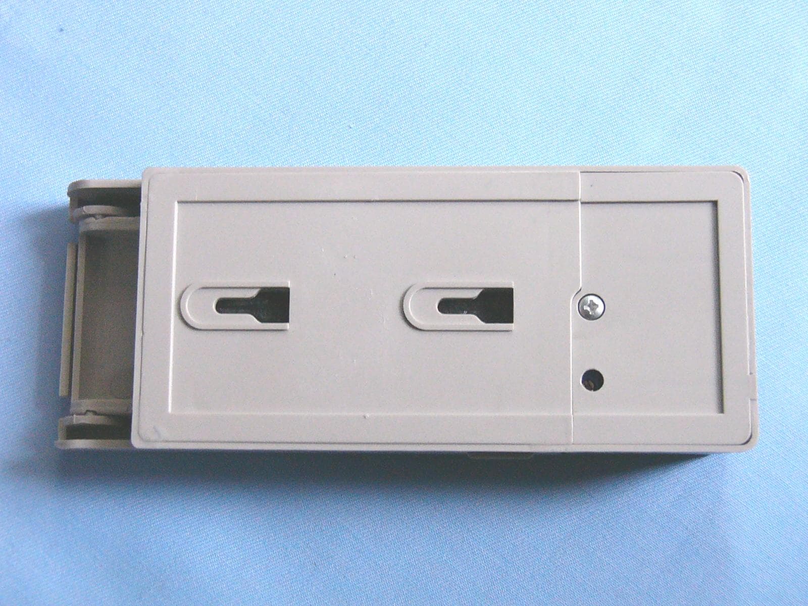
RH7DK310
Apr 01, 2004Digital Keypad
Equipment Class
DSC - Part 15 Security/Remote Control Transmitter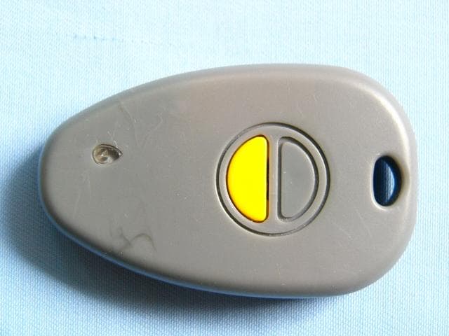
RH7-FP16
Oct 14, 2003Door Transmitter
Equipment Class
DSC - Part 15 Security/Remote Control Transmitter