RI7GE863Data Terminal Module
Telit Communications S.p.A.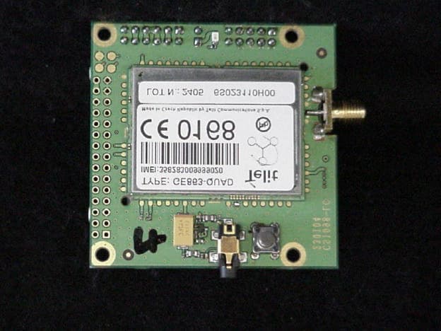
Click to zoom
Application Details
- Equipment Class
- PCB - PCS Licensed Transmitter
- Date of Grant
- Aug 06, 2006
- Application Purpose
- Original Equipment
- Date of Application
- Aug 06, 2006
- Equipment Note
- Data Terminal Module
- Frequency Range
- 1850.13000000 - 1909.80000000
- Company
- Telit Communications S.p.A.
- Country
- Italy
Documents & Files
Document Text
Text extracted from the exhibit documents filed with the FCC. Open a document above to read the original.
Users Manual
Telit GE863-QUAD / GE863-PY Hardware User guide 1vv0300697, Rev. ISSUE#0, - 21/11/05 Reproduction forbidden without Telit Communication written authorization – All Right reserved – Right of modification reserved page 1 of 70 T T e e l l i i t t G G E E 8 8 6 6 3 3 - - Q Q U U A A D D G G E E 8 8 6 6 3 3 - - P P Y Y H H a a r r d d w w a a r r e e U U s s e e r r G G u u i i d d e e © Telit Communications S.p.A. 2004 - 2005 Telit GE863-QUAD / GE863-PY Hardware User guide 1vv0300697, Rev. ISSUE#0, - 21/11/05 Reproduction forbidden without Telit Communication written authorization – All Right reserved – Right of modification reserved page 2 of 70 Contents 1 OVERVIEW 5 2 HARDWARE COMMANDS 6 2.1 Turning ON the GE863-QUAD 6 2.2 Turning OFF the GE863-QUAD 8 2.2.1 Hardware shutdown 8 2.3 Hardware Unconditional Reboot 8 3 POWER SUPPLY 10 3.1 Power Supply Requirements 10 3.2 General Design Rules 10 3.2.1 Electrical design Guidelines 11 3.2.1.1 + 5V input Source Power Supply Design Guidelines 11 3.2.1.2 + 12V input Source Power Supply Design Guidelines 12 3.2.1.3 Battery Source Power Supply Design Guidelines 13 3.2.1.4 Battery Charge control Circuitry Design Guidelines 13 3.2.2 Thermal Design Guidelines 15 3.2.3 Power Supply PCB layout Guidelines 16 4 ANTENNA 17 4.1 Antenna Requirements 17 4.2 Antenna PCB line Guidelines 18 4.3 Antenna installation Guidelines 19 5 SERIAL PORT 20 5.1 RS232 level translation 22 5.2 5V UART level translation 24 6 MICROPHONE 26 6.1 Microphone line Characteristic and requirements 26 Telit GE863-QUAD / GE863-PY Hardware User guide 1vv0300697, Rev. ISSUE#0, - 21/11/05 Reproduction forbidden without Telit Communication written authorization – All Right reserved – Right of modification reserved page 3 of 70 6.2 General Design Rules 29 6.3 Microphone Biasing 29 6.3.1 Balanced Microphone biasing 30 6.3.2 Unbalanced Microphone biasing 31 6.4 Microphone buffering 32 6.4.1 Buffered Balanced Mic. 32 6.4.2 Buffered Unbalanced (Single Ended) Mic. 34 7 SPEAKER 37 7.1 Speaker lines characteristics and requirements 37 7.2 General Design rules 39 7.2.1 Noise Filtering 40 7.3 Handset earphone design 40 7.4 Hands Free earphone (low power) design 42 7.5 Car Kit speakerphone design 42 8 GENERAL PURPOSE I/O 44 8.1 Using a GPIO pad as INPUT 44 8.2 Using a GPIO pad as OUTPUT 44 8.3 Using the Alarm Output GPIO6 45 8.4 Using the Buzzer Output GPIO7 45 9 CAMERA 46 9.1 Agilent Camera 46 9.1.1 Camera interface connectors 46 9.2 Transchip Camera 48 9.2.1 Camera interface connectors 48 9.2.2 EVB for Agilent and Transchip camera support 51 9.2.3 Block Diagram for supported cameras 52 9.2.4 Schematic Diagrams for supported cameras 53 9.2.5 Example usage script for camera 55 Telit GE863-QUAD / GE863-PY Hardware User guide 1vv0300697, Rev. ISSUE#0, - 21/11/05 Reproduction forbidden without Telit Communication written authorization – All Right reserved – Right of modification reserved page 4 of 70 DOCUMENT CHANGE LOG 57 10 ANNEX A - EVK SCHEMATICS 58 Telit GE863-QUAD / GE863-PY Hardware User guide 1vv0300697, Rev. ISSUE#0, - 21/11/05 Reproduction forbidden without Telit Communication written authorization – All Right reserved – Right of modification reserved page 5 of 70 1 Overview The aim of this document is the description of some hardware solutions useful for developing a product with the Telit GE863-QUAD module. In this document all the basic functions of a mobile phone will be taken into account; for each one of them a proper hardware solution will be suggested and eventually the wrong solutions and common errors to be avoided will be evidenced. Obviously this document can not embrace the whole hardware solutions and products that may be designed. The wrong solutions to be avoided shall be considered as mandatory, while the suggested hardware configurations shall not be considered mandatory, instead the information given shall be used as a guide and a starting point for properly developing your product with the Telit GE863-QUAD module. For further hardware details that may not be explained in this document refer to the Telit GE863-QUAD Product Description document where all the hardware information is reported. NOTICE The information presented in this document is believed to be accurate and reliable. However, no responsibility is assumed by Telit Communication S.p.A. for its use, nor any infringement of patents or other rights of third parties which may result from its use. No license is granted by implication or otherwise under any patent rights of Telit Communication S.p.A. other than for circuitry embodied in Telit products. This document is subject to change without notice . Telit GE863-QUAD / GE863-PY Hardware User guide 1vv0300697, Rev. ISSUE#0, - 21/11/05 Reproduction forbidden without Telit Communication written authorization – All Right reserved – Right of modification reserved page 6 of 70 2 Hardware Commands 2.1 Turning ON the GE863-QUAD To turn on the GE863-QUAD the pad ON# must be tied low for at least 1 second and then released. The maximum current that can be drained from the ON# pad is 0,1 mA. A simple circuit to do it is: NOTE: don't use any pull up resistor on the ON# line, it is internally pulled up. Using pull up resistor may bring to latch up problems on the GE863-QUAD power regulator and improper power on/off of the module. The line ON# must be connected only in open collector configuration. NOTE: In this document all the lines that are inverted, hence have active low signals are labeled with a name that ends with a "#" or with a bar over the name. NOTE: The GE863-QUAD turns fully on also by supplying power to the Charge pad (provided there's a battery on the VBATT pads). ON# Power ON impulse GND R1 R2 Q1 Telit GE863-QUAD / GE863-PY Hardware User guide 1vv0300697, Rev. ISSUE#0, - 21/11/05 Reproduction forbidden without Telit Communication written authorization – All Right reserved – Right of modification reserved page 7 of 70 For example: 1- Let's assume you need to drive the O…
Text truncated - open the document above for the full version.
Cover Letter(s)
CONFIDENTIALITY REQUEST Federal Communications Commission Date: June 1,2006 Equipment Authorization Branch 7435 Oakland Mills Road Columbia, MD 21046 Gentlemen: Sicom respectfully requests confidentiality of certain materials provided with the submission of GE863 under FCC ID: R17GE863 in accordance with FCC Regulations 0.459. The confidentiality request applies to the following: Parts List, Operational Descriptions, Schematics Block Diagrams and Tune Up Procedures These items are considered as Trade Secrets and therefore public access to the proprietary material could possible result in duplication of equipment that could severely damage the company's business advantage. I appreciate your assistance in this matter. Sincerely, Name: Louis A. Feudi Signature: Title: VP Operations and Engineering Date: June 1, 2006
Cover Letter(s)
3505 Francis Circle Alpharetta, GA 30004 PH: 770-740-0717 Fax: 770-740-1508 www.ustech-lab.com Wednesday, June 21, 2006 To: Mr. Doug Noble ATCB RE: Telit Communications S.p.A. FCC ID: R17GE863 Below are responses to your comments on this Application. 1.) External and Internal photos must show backside of PC boards. Please revise External and Internal photos. Revised and uploaded. 2.) Some of the files and the 731 request confidentiality. There is no confidentiality letter included with this application. Please upload confidentiality letter. Uploaded. 3.) Please upload Licensed Modular Approval letter with all questions answered. Uploaded. 4.) Page 45 of the test report frequency stability section. Limit states 2.5ppm your table shows 9.1ppm. Please explain or retest. Original testing was conducted with improper settings of the spectrum analyzer. The unit was re-tested, and passing results have been provided in the uploaded rev1 of Test Report Part 5. 5.) Application show request for Canadian certification. There doesn’t seem to be any Industry Canada forms with this application. Was Canadian request in error? No, IC is requested. IC forms have now been uploaded. These forms were delayed awaiting Canadian Representative information. Please contact me with any further comments, Sincerely, Louis A. Feudi Operations Manager
External Photos
U.S. Technologies, Inc.Test Report, FCC Part 24E and Part 22H Report Number:06-0008Issue Date: April 18, 2006 Customer: Sicom test s.r.l. Model: GE863-QUAD / GE863-PY Modular Transmitter 47 PHOTOS OF THE TESTED EUT The following photos are attached: Photo 1.EUT Bottom Photo 2.EUT Top with Cover U.S. Technologies, Inc.Test Report, FCC Part 24E and Part 22H Report Number:06-0008Issue Date: April 18, 2006 Customer: Sicom test s.r.l. Model: GE863-QUAD / GE863-PY Modular Transmitter 48 Photo 1.EUT Bottom U.S. Technologies, Inc.Test Report, FCC Part 24E and Part 22H Report Number:06-0008Issue Date: April 18, 2006 Customer: Sicom test s.r.l. Model: GE863-QUAD / GE863-PY Modular Transmitter 49 Photo 5.EUT Top with Cover
ID Label/Location Info
LABEL LAYOUT Doc Center: Daniele Lucà Date: 03/02/06 2001701596 ETICHETTA IMEI PER GE863-QUAD PAG. 1/1 2 1 3 5 4 7 9 GE863-QUAD FCC ID:RI7GE863 IC:5131A-GE863 6 8 Il file fornito è solo indicativo per la grafica e non è adatto alla stampa della etichetta. FILE : imei SUPPORTO : 1vv0200477fpe Dimensioni : 19.5X36 mm LEGENDA: 1) Nome o Tipo apparato: GE863-QUAD 2) Logo Telit (8x4mm) (File telit.tif) 3) IMEI dell’apparato, in chiaro e codice a barre type 128 4) Logo apparato (7x7mm) (File LOGOTRI.PCX) 5) Marchio CE 0168 alto almeno 5mm (15x5mm) (File CE0168babt.tif) 6) Dicitura in chiaro FCC ID: RI7GE863 7) Dicitura in chiaro IC: 5131A-GE863 8) Indicazione “Made in _______ byTelit Communications S.p.A.” (inserire il nome della nazione di produzione) 9) PB Free Logo (4x4mm) (File pb_logo.tif) Documenti applicati: Procedura “DEFINIZIONE E REALIZZAZIONE DELLE ETICHETTE” 80000PR10001 LABEL LAYOUT Doc Center: Daniele Lucà Date: 03/02/06 2001701596 IMEI LABEL FOR GE863-QUAD PAG. 1/1 2 1 3 5 4 7 9 GE863-QUAD FCC ID:RI7GE863 IC:5131A-GE863 6 8 The only purpose of this document is to show the layout.Do not use it to print the real label. FILE : imei RAW LABEL code : 1vv0200477fpe Dimensions : 19.5X36 mm LEGEND: 1) Model type: GE863-QUAD 2) Telit logo (8x4mm) (File telit.tif) 3) IMEI of the apparatus both in figures and in barcode type 128 4) Device Logo (7x7mm) (File LOGOTRI.PCX) 5) CE logo CE0168 – minimum height 5 mm (15x5mm) (File CE0168babt.tif) 6) Clear writing FCC ID: RI7GE863 7) Clear writing IC: 5131A-GE863 8) Clear writing “Made in ______ by Telit Communications S.p.A.” (insert the Production Country) 9) PB Free Logo (4x4mm) (File pb_logo.tif) This document complies with: Procedura “DEFINIZIONE E REALIZZAZIONE DELLE ETICHETTE” 80000PR10001 LABEL LAYOUT Doc Center: Daniele Lucà Date: 03/02/06 2001701598 ETICHETTA IMEI PER GE863-PY PAG. 1/1 2 1 3 5 4 7 9 GE863-PY FCC ID:RI7GE863 IC:5131A-GE863 6 8 Il file fornito è solo indicativo per la grafica e non è adatto alla stampa della etichetta. FILE : imei SUPPORTO : 1vv0200477fpe Dimensioni : 19.5X36 mm LEGENDA: 1) Nome o Tipo apparato: GE863-PY 2) Logo Telit (8x4mm) (File telit.tif) 3) IMEI dell’apparato, in chiaro e codice a barre type 128 4) Logo apparato (7x7mm) (File LOGOTRI.PCX) 5) Marchio CE 0168 alto almeno 5mm (15x5mm) (File CE0168babt.tif) 6) Dicitura in chiaro FCC ID: RI7GE863 7) Dicitura in chiaro IC: 5131A-GE863 8) Indicazione della Nazione in cui l'apparecchiatura viene prodotta “Made in _______ by Telit Communications S.p.A.” (inserire il nome della nazione di produzione) 9) PB Free Logo (4x4mm) (File pb_logo.tif) Documenti applicati: Procedura “DEFINIZIONE E REALIZZAZIONE DELLE ETICHETTE” 80000PR10001 LABEL LAYOUT Doc Center: Daniele Lucà Date: 03/02/06 2001701598 IMEI LABEL FOR GE863-PY PAG. 1/1 2 1 3 5 4 7 9 GE863-PY FCC ID:RI7GE863 IC:5131A-GE863 6 8 The only purpose of this document is to show the layout.Do not use it to print the real label. FILE : imei RAW LABEL code : 1vv0200477fpe Dimensions : 19.5X36 mm LEGEND: 1) Model type: GE863-PY 2) Telit logo (8x4mm) (File telit.tif) 3) IMEI of the apparatus both in figures and in barcode type 128 4) Device logo (7x7mm) (File LOGOTRI.PCX) 5) CE logo CE0168 – minimum height 5 mm (15x5mm) (File CE0168babt.tif) 6) Clear writing FCC ID: RI7GE863 7) Clear writing IC: 5131A-GE863 8) Country of production “Made in ______ by Telit Communications S.p.A.” (insert the Production Country) 9) PB Free Logo (4x4mm) (File pb_logo.tif) This document complies with: Procedura “DEFINIZIONE E REALIZZAZIONE DELLE ETICHETTE” 80000PR10001
Internal Photos
54 Photo1. Top of EUT with shield removed 55 Photo2. Bottom of EUT
RF Exposure Info
U.S. Technologies, Inc . Test Report, FCC Part 24E and Part 22H Report Number:06-0008Issue Date: April 18, 2006 Customer: Sicom test s.r.l. Model: GE863-QUAD / GE863-QUAD-PY Modular Transmitter RF EXPOSURE U.S. Technologies, Inc . Test Report, FCC Part 24E and Part 22H Report Number:06-0008Issue Date: April 18, 2006 Customer: Sicom test s.r.l. Model: GE863-QUAD / GE863-QUAD-PY Modular Transmitter 5.1 RF Safety Requirements to 2.1091 for Mobile Transmitters Telit, Inc. calculated the MPE emission values for a GE863 with a maximum power density when using a 3 dBi antenna for fixed and mobile applications. They used the formula shown in OET Bulletin 65 and calculated the minimum distance between antenna and unsuspecting user as 20 cm for both applications. Power Output The EUT’s maximum expected output power as shown in Section 2.6 was 824 MHz to 850 MHz Range Frequency of Fundamental (MHz) Measurement (dBm) Measurement (Watt) 824.0931.121.294 835.9230.291.069 848.7029.990.997 The maximum EIRP expected for all installations is with a +3dBi gain antenna. This would yield a maximum EIRP of 31.12 dBm + 3 dBi = +34.12 dBm. Therefore the maximum radiated output power (EIRP) is : Antilog(34.12 dBm/10) = 2582 mW U.S. Technologies, Inc . Test Report, FCC Part 24E and Part 22H Report Number:06-0008Issue Date: April 18, 2006 Customer: Sicom test s.r.l. Model: GE863-QUAD / GE863-QUAD-PY Modular Transmitter MPE Calculations The limits for this unit (uncontrolled exposure) are 0.55 mW/cm 2 . Taking the RF Denisty Field Equation: S = (EIRP in mW)/(4πR 2 ) Where R = 20 cm and EIRP = 2582 mW andπ = 3.14159 S = 2582/4π20 2 S = 2582/5026.55 S = 0.51 mW/cm 2 All manual instructions will specify 20 cm all installations. U.S. Technologies, Inc . Test Report, FCC Part 24E and Part 22H Report Number:06-0008Issue Date: April 18, 2006 Customer: Sicom test s.r.l. Model: GE863-QUAD / GE863-QUAD-PY Modular Transmitter 1850 MHz to 1910 MHz Range Frequency of Fundamental (MHz) Measurement (dBm) Measurement (Watt) 1.8501328.540.714 1.8799026.370.433 1.9098027.680.586 The maximum EIRP expected for all installations is with a +3dBi gain antenna. This would yield a maximum EIRP of 28.54 dBm + 3 dBi = +31.54 dBm. Therefore the maximum radiated output power (EIRP) is : Antilog(30.68 dBm/10) = 1426 mW MPE Calculations The limits for this unit (uncontrolled exposure) are 1.0 mW/cm 2 . Taking the RF Denisty Field Equation: S = (EIRP in mW)/(4πR 2 ) Where R = 20 cm and EIRP = 21172 mW andπ = 3.14159 S = 1426/4π20 2 S = 1426/5026.55 S = 0.28 mW/cm 2 All manual instructions will specify 20 cm all installations. U.S. Technologies, Inc . Test Report, FCC Part 24E and Part 22H Report Number:06-0008Issue Date: April 18, 2006 Customer: Sicom test s.r.l. Model: GE863-QUAD / GE863-QUAD-PY Modular Transmitter 5.2 RF Safety Requirements to 2.1091 (d) for Mobile Transmitters Maximum output power is 34.12 dBm. (824.09 MHz) Thje unit features GPRS Class 10 (2 up, 4 down) as described on page 4 of the Technical manual. With a total time averaging of 8 packets, the 2 packet upload yields a duty cycle of 2/8 = .25 or 25%. Using the formula for duty cycle correction = 10 log (0.25) = -6dB, the ERP is calculated as follows: ERP = Antilog ((34.12 – 6 – 2.14)/10) ERP = Antilog (2.598) ERP = 0.396 W The maximum allowed exposure is 1.5 Watts, therefore, this unit meets the requirements of <1,5 GHZ. Maximum output power is 31.54 dBm. (1850.13 MHz) Thje unit features GPRS Class 10 (2 up, 4 down) as described on page 4 of the Technical manual. With a total time averaging of 8 packets, the 2 packet upload yields a duty cycle of 2/8 = .25 or 25%. Using the formula for duty cycle correction = 10 log (0.25) = -6dB, the ERP is calculated as follows: ERP = Antilog ((31.54 – 6 – 2.14)/10) ERP = Antilog (2.34) ERP = 0.219 W The maximum allowed exposure is 3 Watts, therefore, this unit meets the requirements of >1,5 GHZ.
Test Report
April 18, 2006 Mr. Roberto Passini Sicom test s.r.l. Via Dante 5, 34100 Trieste Italy Dear Mr. Passini: Enclosed please find Sicom test s.r.l., file copy of the FCC Part 24E and Part 22H Certification Report for the GE863-QUAD / GE863-PY Modular Transmitter. Please sign the signature page of the report and keep it in your files as proof that the product has been tested. If you have any questions, please don't hesitate to call. Thank you for your business. Sincerely, Louis A. Feudi VP / Operations & Engineering 3505 Francis Circle Alpharetta, GA 30004 PH: 770-740-0717 Fax: 770-740-1508 www.ustech-lab.com FCC Part 24E and Part 22H, Certification Application of the Sicom test s.r.l. Model: GE863-QUAD / GE863-PY Modular Transmitter Issue Date: April 18, 2006 UST Project No.: 06-0008 3505 Francis Circle Alpharetta, GA 30004 PH: 770-740-0717 Fax: 770-740-1508 www.ustech-lab.com TABLE OF CONTENTS SECTION 1 GENERAL INFORMATION 1.1Product Description 1.2Related Submittal(s) SECTION 2 TESTS AND MEASUREMENTS 2.1Configuration of Tested EUT 2.2Test Facility 2.3Test Equipment 2.4Modifications 2.5Antenna Description 2.6 Conducted RF Power Output 2.7Field Strength of Spurious Radiation 2.8Band-Edge Compliance 2.999% Occupied Bandwidth 2.10Spurious Emissions at Antenna Terminals 2.11Frequency Stability, Voltage and Temperature Variation SECTION 3 PHOTOGRAPHS LIST OF FIGURES AND TABLES FIGURES 1)Test Configuration 2) Photographs for Spurious Emissions 3) Conducted RF Power Output 4) Band-Edge Compliance 5) 99% Occupied Bandwidth 6) Spurious Emissions at Antenna Terminals TABLES 1)EUT and Peripherals 2) Test Instruments 3) Conducted RF Power Output 4) Field Strength of Spurious Radiation 5) Band-Edge Compliance 6) Field Strength of Spurious Radiation U.S. Technologies, Inc.Test Report, FCC Part 24E and Part 22H Report Number:06-0008Issue Date: April 18, 2006 Customer: Sicom test s.r.l. Model: GE863-QUAD / GE863-PY Modular Transmitter 1 SECTION 1 GENERAL INFORMATION U.S. Technologies, Inc.Test Report, FCC Part 24E and Part 22H Report Number:06-0008Issue Date: April 18, 2006 Customer: Sicom test s.r.l. Model: GE863-QUAD / GE863-PY Modular Transmitter 2 GENERAL INFORMATION 1.1Product Description The Equipment Under Test is the Telit. GM863-QUAD Quad Band GSM-GPRS Data Terminal Module. The EUT is a small, lightweight and low power consumption device. Powered at 3.7 volts and BGA mounted. Can be supplied with onboard memory from 4 to 8 MB. A commercial version of the device, named GM863-PY, is supplied with 8 MB of memory onboard and the pyton interpreter installed. U.S. Technologies, Inc.Test Report, FCC Part 24E and Part 22H Report Number:06-0008Issue Date: April 10, 2006 Customer: Sicom test s.r.l. Model: GE863-QUAD / GE863-PY Modular Transmitter 3 1.2Related Submittal(s)/Grant(s) The EUT is subject to the following authorizations: a)Certification as a transceiver as specified by Part 24E and Part 22H. The information contained in this report is presented for the Part 24E and Part 22H Certification authorization(s) for the EUT. U.S. Technologies, Inc.Test Report, FCC Part 24E and Part 22H Report Number:06-0008Issue Date: April 10, 2006 Customer: Sicom test s.r.l. Model: GE863-QUAD / GE863-PY Modular Transmitter 4 SECTION 2 TEST AND MEASUREMENTS U.S. Technologies, Inc.Test Report, FCC Part 24E and Part 22H Report Number:06-0008Issue Date: April 10, 2006 Customer: Sicom test s.r.l. Model: GE863-QUAD / GE863-PY Modular Transmitter 5 TEST AND MEASUREMENTS 2.1 Configuration of Tested System Prepared in accordance with the requirements of the FCC Rules and Regulations Part 2, 22 & 24. All measurements are peak unless stated otherwise. The video filter associated with the spectrum analyzer was off throughout the evaluation process. Interconnecting cables were manipulated as necessary to maximize emissions. A block diagram of the tested system is shown in Figure 1. Test configuration photographs for spurious emissions are shown in Figure 2. The sample used for testing was received by U.S. Technologies on February 13, 2006 and March 14, 2006 in good condition. 2.2 Test Facility Testing was performed at US Tech's measurement facility at 3505 Francis Circle, Alpharetta, GA.This site has been fully described and registered by the FCC under Registration Number 91037. Additionally, this site has also been fully described and submitted to Industry Canada (IC), and has been approved under file IC2982. 2.3 Test Equipment Table 2 describes test equipment used to evaluate this product. 2.4 Modifications No modifications were made by US Tech to bring the EUT into compliance with FCC Part 24E and Part 22H limits for the transmitter portion of the EUT. U.S. Technologies, Inc.Test Report, FCC Part 24E and Part 22H Report Number:06-0008Issue Date: April 10, 2006 Customer: Sicom test s.r.l. Model: GE863-QUAD / GE863-PY Modular Transmitter 6 FIGURE 1 TEST CONFIGURATION 119” U 120 VAC/ 60 Hz Control Board (EUT) DC Power Supply Laptop Computer 50 Termination Direct Connect 23” U 38” U Data Cable 70” U 120 VAC/ 60 Hz For Configuration Only U.S. Technologies, Inc.Test Report, FCC Part 24E and Part 22H Report Number:06-0008Issue Date: April 10, 2006 Customer: Sicom test s.r.l. Model: GE863-QUAD / GE863-PY Modular Transmitter 7 FIGURE 2a Photographs for Spurious Emissions EUT Front U.S. Technologies, Inc.Test Report, FCC Part 24E and Part 22H Report Number:06-0008Issue Date: April 10, 2006 Customer: Sicom test s.r.l. Model: GE863-QUAD / GE863-PY Modular Transmitter 8 FIGURE 2b Photographs for Spurious Emissions EUT Back U.S. Technologies, Inc.Test Report, FCC Part 24E and Part 22H Report Number:06-0008Issue Date: April 10, 2006 Customer: Sicom test s.r.l. Model: GE863-QUAD / GE863-PY Modular Transmitter 9 TABLE 1 EUT and Peripherals PERIPHERAL MANUFACTURER MODEL NUMBER SERIAL NUMBER FCC ID:CABLES P/D Sicom test s.r.l. (EUT) GE863-QUAD / GE863-PY NoneNoneNone 50 Termination NoneNoneNoneNone DC Power Supply Hewlett Packard HP Power Supply…
Text truncated - open the document above for the full version.
Test Report
U.S. Technologies, Inc.Test Report, FCC Part 24E and Part 22H Report Number:06-0008Issue Date: April 18, 2006 Customer: Sicom test s.r.l. Model: GE863-QUAD / GE863-PY Modular Transmitter 11 2.5 Antenna Description No antenna is provided (or supplied to the market) together with the product. U.S. Technologies, Inc.Test Report, FCC Part 24E and Part 22H Report Number:06-0008Issue Date: April 18, 2006 Customer: Sicom test s.r.l. Model: GE863-QUAD / GE863-PY Modular Transmitter 12 2.6 Conducted RF Power Output (FCC Section 2.1046) § 2.1046 Measurements required: RF power output. (a) For transmitters other than single sideband, independent sideband and controlled carrier radiotelephone, power output shall be measured at the RF output terminals when the transmitter is adjusted in accordance with the tuneup procedure to give the values of current and voltage on the circuit elements specified in § 2.1033(c)(8). The electrical characteristics of the radio frequency load attached to the output terminals when this test is made shall be stated. (b) For single sideband, independent sideband, and single channel, controlled carrier radiotelephone transmitters the procedure specified in paragraph (a) of this section shall be employed and, in addition, the transmitter shall be modulated during the test as follows. In all tests, the input level of the modulating signal shall be such as to develop rated peak envelope power or carrier power, as appropriate, for the transmitter. (c) For measurements conducted pursuant to paragraphs (a) and (b) of this section, all calculations and methods used by the applicant for determining carrier power or peak envelope power, as appropriate, on the basis of measured power in the radio frequency load attached to the transmitter output terminals shall be shown. Under the test conditions specified, no components of the emission spectrum shall exceed the limits specified in the applicable rule parts as necessary for meeting occupied bandwidth or emission limitations. U.S. Technologies, Inc.Test Report, FCC Part 24E and Part 22H Report Number:06-0008Issue Date: April 18, 2006 Customer: Sicom test s.r.l. Model: GE863-QUAD / GE863-PY Modular Transmitter 13 TABLE 3a CONDUCTED RF POWER OUTPUT 824 MHz to 848 MHz Range Frequency of Fundamental (MHz) Measurement (dBm) Measurement (Watt) 824.0931.121.294 835.9230.291.069 848.7029.990.997 2.85 dB added for cable and Attenuator loss Calculation: Antilog( 31.12/10 ) = 1.294 w Test Date: April 5, 2006 Tester Signature: Name: Austin Thompson U.S. Technologies, Inc.Test Report, FCC Part 24E and Part 22H Report Number:06-0008Issue Date: April 18, 2006 Customer: Sicom test s.r.l. Model: GE863-QUAD / GE863-PY Modular Transmitter 14 Figure 3a. Conducted RF Power Output U.S. Technologies, Inc.Test Report, FCC Part 24E and Part 22H Report Number:06-0008Issue Date: April 18, 2006 Customer: Sicom test s.r.l. Model: GE863-QUAD / GE863-PY Modular Transmitter 15 Figure 3b. Conducted RF Power Output U.S. Technologies, Inc.Test Report, FCC Part 24E and Part 22H Report Number:06-0008Issue Date: April 18, 2006 Customer: Sicom test s.r.l. Model: GE863-QUAD / GE863-PY Modular Transmitter 16 Figure 3c. Conducted RF Power Output U.S. Technologies, Inc.Test Report, FCC Part 24E and Part 22H Report Number:06-0008Issue Date: April 18, 2006 Customer: Sicom test s.r.l. Model: GE863-QUAD / GE863-PY Modular Transmitter 17 TABLE 3b CONDUCTED RF POWER OUTPUT 1850 MHz to 1909 MHz Range Frequency of Fundamental (MHz) Measurement (dBm) Measurement (Watt) 1.8501328.540.714 1.8799026.370.433 1.9098027.680.586 1.17 dB added for cable and Attenuator loss Calculation: Antilog( 28.54/10 ) = 0.714 w Test Date: April 5, 2006 Tester Signature: Name: Austin Thompson U.S. Technologies, Inc.Test Report, FCC Part 24E and Part 22H Report Number:06-0008Issue Date: April 18, 2006 Customer: Sicom test s.r.l. Model: GE863-QUAD / GE863-PY Modular Transmitter 18 Figure 3d. Conducted RF Power Output U.S. Technologies, Inc.Test Report, FCC Part 24E and Part 22H Report Number:06-0008Issue Date: April 18, 2006 Customer: Sicom test s.r.l. Model: GE863-QUAD / GE863-PY Modular Transmitter 19 Figure 3e. Conducted RF Power Output U.S. Technologies, Inc.Test Report, FCC Part 24E and Part 22H Report Number:06-0008Issue Date: April 18, 2006 Customer: Sicom test s.r.l. Model: GE863-QUAD / GE863-PY Modular Transmitter 20 Figure 3f. Conducted RF Power Output U.S. Technologies, Inc.Test Report, FCC Part 24E and Part 22H Report Number:06-0008Issue Date: April 18, 2006 Customer: Sicom test s.r.l. Model: GE863-QUAD / GE863-PY Modular Transmitter 21 2.7 Field Strength of Spurious Radiation (FCC Section 2.1053) Spurious emissions were evaluated from 30 MHz to 19.1 GHz at an EUT to antenna distance of 1 or 3 meters. The EUT was tested with an external power source and modulated by its own internal sources. A low, middle and high channel were tested. The EUT was placed on an open area test site and the spurious emissions tested as stipulated by EIT/TIA-603: 1992 section 2.2.12. Measurements for 30 to 1000 MHz were made with the analyzer's bandwidth set to 120 kHz. Measurements above 1 GHz were made with the analyzer's bandwidth set to 1 MHz. The worse case results are shown in Table 4a. Initial measurements were calculated to determine margin in dB from the Limit. Any margin less than 20dB was repeated using the substitution Method of EIA/TIA-603:1992 section 2.2.1.2. Substitution Method results are shown in table 4b. FCC Minimum Standard (FCC Section 24.238) On any frequency outside a licensee’s frequency block, the power of any transmission shall be attenuated below the transmitter power (P) by at least 43 + 10 log (P) dB. U.S. Technologies, Inc.Test Report, FCC Part 24E and Part 22H Report Number:06-0008Issue Date: April 18, 2006 Customer: Sicom test s.r.l. Model: GE863-QUAD / GE863-PY Modular Transmitter 22 TABLE 4a RADIATED RF POWER OUTPUT Radiated Emissions (Theoretical) Test By: Test:Substitution for GM86…
Text truncated - open the document above for the full version.
Test Report
U.S. Technologies, Inc.Test Report, FCC Part 24E and Part 22H Report Number:06-0008Issue Date: April 18, 2006 Customer: Sicom test s.r.l. Model: GE863-QUAD / GE863-PY Modular Transmitter 24 2.8 Band-Edge Compliance (FCC Section 24.238) On any frequency outside a licensee’s frequency block, the power of any transmission shall be attenuated below the transmitter power (P) by at least 43 + 10 log (P) dB. U.S. Technologies, Inc.Test Report, FCC Part 24E and Part 22H Report Number:06-0008Issue Date: April 18, 2006 Customer: Sicom test s.r.l. Model: GE863-QUAD / GE863-PY Modular Transmitter 25 TABLE 5 BAND-EDGE COMPLIANCE Frequency (MHz) Level (dBm) Limit (dBm) < 824-17.67*-13 > 849-18.48*-13 < 1850-23.69**-13 > 1910-19.31**-13 *= 2.64 dB added for Cable and Attenuator Loss ** = 1.07 dB added for Cable and Attenuator Loss Test Date: April 14, 2006 Tester Signature: Name: Austin Thompson U.S. Technologies, Inc.Test Report, FCC Part 24E and Part 22H Report Number:06-0008Issue Date: April 18, 2006 Customer: Sicom test s.r.l. Model: GE863-QUAD / GE863-PY Modular Transmitter 26 Figure 4a. Band Edge Compliance U.S. Technologies, Inc.Test Report, FCC Part 24E and Part 22H Report Number:06-0008Issue Date: April 18, 2006 Customer: Sicom test s.r.l. Model: GE863-QUAD / GE863-PY Modular Transmitter 27 Figure 4b. Band Edge Compliance U.S. Technologies, Inc.Test Report, FCC Part 24E and Part 22H Report Number:06-0008Issue Date: April 18, 2006 Customer: Sicom test s.r.l. Model: GE863-QUAD / GE863-PY Modular Transmitter 28 Figure 4c. Band Edge…
Text truncated - open the document above for the full version.
Contact Information
Applicant
Paolomaria Schiratti(VP Global Certification)
Technical Contact
US TechLouis Feudi
[email protected]770-740-0717
3505 Francis Circle · Alphareatta, Georgia · United States
Test Firm
US TechGeorge Yang
Technical Specifications
| # | Rule Parts | Frequency Range | Power Output | Emission | Tolerance |
|---|---|---|---|---|---|
| 2 | 24E | 1.85 GHz - 1.91 GHz | 714.00 mW | 300KGXW | 1 ppm |
Other Applications from Telit Communications S.p.A.
RI7FE910C04WWI
Jul 01, 20265G Radio Module
Equipment Class
PCB - PCS Licensed TransmitterRI7FE910C04NA
Jun 23, 20265G Radio Module
Equipment Class
CBE - Citizens Band End User DevicesRI7LE910T1SN
Apr 09, 2026LE910T1-SN
Equipment Class
JBP - Part 15 Class B Computing Device PeripheralRI7ME310T1W1
Mar 11, 2026ME310T1-W1
Equipment Class
PCB - PCS Licensed TransmitterRI7LE310X1LA
Jan 08, 2026LTE Cat 1 bis module
Equipment Class
JBP - Part 15 Class B Computing Device Peripheral