RI7GE863LQuad-Band GSM/GPRS module - Type: GE863
Telit Communications S.p.A.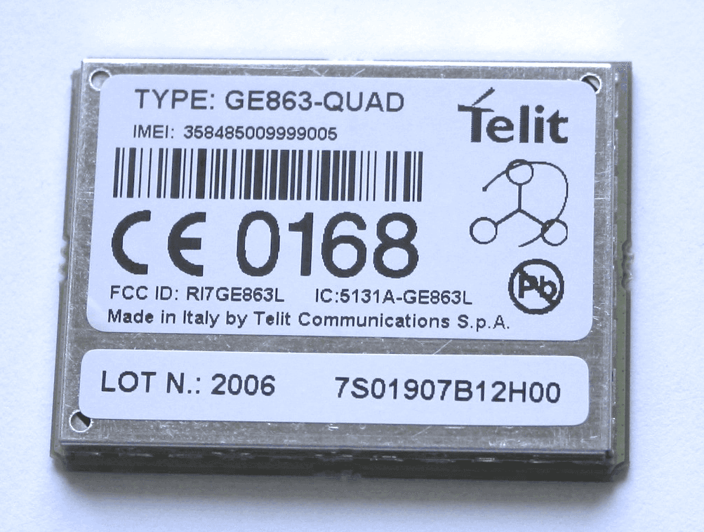
Click to zoom
Application Details
- Equipment Class
- PCB - PCS Licensed Transmitter
- Date of Grant
- Jul 16, 2006
- Application Purpose
- Original Equipment
- Date of Application
- Jul 16, 2006
- Equipment Note
- Quad-Band GSM/GPRS module - Type: GE863
- Frequency Range
- 1850.20000000 - 1909.80000000
- Company
- Telit Communications S.p.A.
- Country
- Italy
Documents & Files
Document Text
Text extracted from the exhibit documents filed with the FCC. Open a document above to read the original.
Users Manual
Telit GE863-QUAD / GE863-PY Hardware User guide 1vv0300715, Rev. ISSUE#0, - 21/02/06 Reproduction forbidden without Telit Communication written authorization – All Right reserved – Right of modification reserved page 1 of 71 T T e e l l i i t t G G E E 8 8 6 6 3 3 - - Q Q U U A A D D G G E E 8 8 6 6 3 3 - - P P Y Y H H a a r r d d w w a a r r e e U U s s e e r r G G u u i i d d e e © Telit Communications S.p.A. 2004 - 2005 Telit GE863-QUAD / GE863-PY Hardware User guide 1vv0300715, Rev. ISSUE#0, - 21/02/06 Reproduction forbidden without Telit Communication written authorization – All Right reserved – Right of modification reserved page 2 of 71 Contents 1 OVERVIEW 5 2 HARDWARE COMMANDS 6 2.1 Turning ON the GE863-QUAD/PY 6 2.2 Turning OFF the GE863-QUAD/PY 8 2.2.1 Hardware shutdown 8 2.3 Hardware Unconditional Reboot 8 3 POWER SUPPLY 10 3.1 Power Supply Requirements 10 3.2 General Design Rules 11 3.2.1 Electrical design Guidelines 11 3.2.1.1 + 5V input Source Power Supply Design Guidelines 11 3.2.1.2 + 12V input Source Power Supply Design Guidelines 13 3.2.1.3 Battery Source Power Supply Design Guidelines 14 3.2.1.4 Battery Charge control Circuitry Design Guidelines 14 3.2.2 Thermal Design Guidelines 16 3.2.3 Power Supply PCB layout Guidelines 17 4 ANTENNA 18 4.1 GSM Antenna Requirements 18 4.2 GSM Antenna - PCB line Guidelines 19 4.3 GSM Antenna - installation Guidelines 20 5 SERIAL PORTS 20 5.1 MODEM SERIAL PORT 20 5.2 MODEM SERIAL PORT 2 (DEBUG) 22 5.3 RS232 level translation 23 5.4 5V UART level translation 25 Telit GE863-QUAD / GE863-PY Hardware User guide 1vv0300715, Rev. ISSUE#0, - 21/02/06 Reproduction forbidden without Telit Communication written authorization – All Right reserved – Right of modification reserved page 3 of 71 6 MICROPHONE 27 6.1 Microphone line Characteristic and requirements 27 6.2 General Design Rules 30 6.3 Microphone Biasing 30 6.3.1 Balanced Microphone biasing 31 6.3.2 Unbalanced Microphone biasing 33 6.4 Microphone buffering 34 6.4.1 Buffered Balanced Mic. 34 6.4.2 Buffered Unbalanced (Single Ended) Mic. 37 7 SPEAKER 40 7.1 Speaker lines characteristics and requirements 40 7.2 General Design rules 42 7.2.1 Noise Filtering 43 7.3 Handset earphone design 43 7.4 Hands Free earphone (low power) design 45 7.5 Car Kit speakerphone design 45 8 GENERAL PURPOSE I/O 47 8.1 Using a GPIO pad as INPUT 47 8.2 Using a GPIO pad as OUTPUT 47 8.3 Using the Alarm Output GPIO6 48 8.4 Using the Buzzer Output GPIO7 48 9 CAMERA 49 9.1 Transchip Camera 49 9.1.1 Camera interface connectors 49 9.1.2 EVB for Transchip camera support 52 9.1.3 Block Diagram for supported cameras 53 9.1.4 Schematic Diagrams for supported cameras 54 9.1.5 Example usage script for camera 55 Telit GE863-QUAD / GE863-PY Hardware User guide 1vv0300715, Rev. ISSUE#0, - 21/02/06 Reproduction forbidden without Telit Communication written authorization – All Right reserved – Right of modification reserved page 4 of 71 10 CONFORMITY ASSESSMENT ISSUES 57 11 SAFETY RECOMMANDATIONS 59 DOCUMENT CHANGE LOG 61 12 EVK 2 SCHEMATICS 62 13 EVB CAMERA SCHEMATICS 68 Telit GE863-QUAD / GE863-PY Hardware User guide 1vv0300715, Rev. ISSUE#0, - 21/02/06 Reproduction forbidden without Telit Communication written authorization – All Right reserved – Right of modification reserved page 5 of 71 1 Overview The aim of this document is the description of some hardware solutions useful for developing a product with the Telit GE863-QUAD/PY module. In this document all the basic functions of a mobile phone will be taken into account; for each one of them a proper hardware solution will be suggested and eventually the wrong solutions and common errors to be avoided will be evidenced. Obviously this document cannot embrace the whole hardware solutions and products that may be designed. The wrong solutions to be avoided shall be considered as mandatory, while the suggested hardware configurations shall not be considered mandatory, instead the information given shall be used as a guide and a starting point for properly developing your product with the Telit GE863-QUAD/PY module. For further hardware details that may not be explained in this document refer to the Telit GE863-QUAD/PY Product Description document where all the hardware information is reported. NOTICE The information presented in this document is believed to be accurate and reliable. However, no responsibility is assumed by Telit Communication S.p.A. for its use, nor any infringement of patents or other rights of third parties which may result from its use. No license is granted by implication or otherwise under any patent rights of Telit Communication S.p.A. other than for circuitry embodied in Telit products. This document is subject to change without notice . Telit GE863-QUAD / GE863-PY Hardware User guide 1vv0300715, Rev. ISSUE#0, - 21/02/06 Reproduction forbidden without Telit Communication written authorization – All Right reserved – Right of modification reserved page 6 of 71 2 Hardware Commands 2.1 Turning ON the GE863-QUAD/PY To turn on the GE863-QUAD/PY the pad ON# must be tied low for at least 1 second and then released. The maximum current that can be drained from the ON# pad is 0,1 mA. A simple circuit to do it is: NOTE: don't use any pull up resistor on the ON# line, it is internally pulled up. Using pull up resistor may bring to latch up problems on the GE863-QUAD/PY power regulator and improper power on/off of the module. The line ON# must be connected only in open collector configuration. NOTE: In this document all the lines that are inverted, hence have active low signals are labeled with a name that ends with a "#" or with a bar over the name. NOTE: The GE863-QUAD/PY turns fully on also by supplying power to the Charge pad (provided there's a battery on the VBATT pads). ON# Power ON impulse GND R1 R2 Q1 Telit GE863-QUAD / GE863-PY Hardware User guide 1vv0300715, Rev. ISSUE#0, - 21/02/06 Reproduction forbidden without Telit Communication written authorization – A…
Text truncated - open the document above for the full version.
Cover Letter(s)
Federal Communication Commission Equipment Authorization Division, Application Processing Branch 7435 Oakland Mills Road Columbia, MD 21048 July 12, 2006 RE: 15.19 Statement (FCC ID: RI7GE863L) TO WHOM IT MAY CONCERN The statement: "This device complies with Part 15 of the FCC Rules. Operation is subject to the following two conditions: (1) this device may not cause harmful interference, and (2) this device must accept any interference received, including interference that may cause undesired operation” Is not placed in the label of the equipment due to the following reasons: - Type label is too small (No room for this writing). - Required text is already included in the user guide This statement is placed in a prominent location in the instruction manual. Please contact me if there is any information you may need. If you have any questions, please feel free to contact me at the address shown below. Sincerely, P.A. Mr. Sandro Spanghero Technical Director Telit Communications S.p.A. Viale Stazione di Prosecco 5/B, I-34010 Trieste, Italy
Cover Letter(s)
attn: Reviewing Engineer Federal Communications Commission 7435 Oakland Mills Road Columbia, MD 21046 RE: LETTER OF AGENT AUTHORIZATION July 12, 2006 To Whom It May Concern: We, the undersigned, hereby authorize MET Laboratories, Inc. to act on our behalf in all matters relating to application for equipment authorizations (FCC ID: RI7GE863L), including the signing of all documents relating to these matters. We also hereby certify that no party to the application authorized hereunder is subject to the denial of benefits, including FCC benefits, pursuant to Section 5301 of the Anti-Drug Abuse Act of 1988,21 U.S.C.853(a). This agreement expires one year from the current date. Sincerely, P.A. Mr. Sandro Spanghero Technical Director Telit Communications S.p.A. Viale Stazione di Prosecco 5/B, I-34010 Trieste, Italy
Cover Letter(s)
DOC-FCC009 4/14/2005 Page 1 of 3 FEDERAL COMMUNICATIONS COMMISSION - FCC FORM 731 APPLICATION FOR EQUIPMENT AUTHORIZATION Approved by OMB 3060 - 0934 Expires 2006-03-14 Item 1. Applicant's complete, legal business name: Telit Communications S.p.A. Item 2. Applicant's mailing address Line 1: Via Stazione di Prosecco 5/B Line 2: P.O.Box: City: Trieste State: Country (if foreign address): Italy Zip/Postal Code: I-34010 Item 3. FCC ID: RI7GE863L Grantee code: RI7 Equipment Product Code (14 characters max imum): GE863L Item 4. Person at the applicant's address to receive grant or for contact: First Name: Mail Stop: Last Name: Telephone: Ext: Title: E-mail: Fax No: Item 5. Instead of Applicant, the original Grant is authorized to be mailed to: Centro de Tecnología de las Comunicaciones S.A. (CETECOM) Paque Tecnologico de Andalucía Severo Ochoa 2 E-29590 Campanillas, Málaga SPAIN ATTN: Ricardo Orejas Phone: +34952619317 Fax: +34952619113 E-mail: [email protected] Item 6. Technical Contact: Firm Name: Telit Communications S.p.A. Telephone: +39 040 4192111 Ext: Fax No: +39 040 4192110 First Name: Sandro Middle Initial: Last Name: Spanghero Address Line 1: Via Stazione di Prosecco 5/B P.O.Box: Address Line 2: City: Trieste Country (if foreign address): Italy Zip/Postal Code: I-34010 E-mail: [email protected] Item 7. Non-Technical Contact: Firm Name: Telit Communications S.p.A. Telephone: +39 040 4192111 Ext: Fax No: +39 040 4192110 First Name: Sandro Middle Initial: Last Name: Spanghero Address Line 1: Via Stazione di Prosecco 5/B P.O.Box: Address Line 2: City: Trieste Country (if foreign address): Italy Zip/Postal Code: I-34010 E-mail: [email protected] Item 8. * Does this application include a request for confidentiality for any portion(s) of the data contained in this application pursuant to 47 CFR § 0.459 of the Commission Rules? If "Yes" see instructions. (please mark as appropriate) X Yes Ο No Item 9. Does the applicant request that the Commission defer grant of this application pursuant 47 CFR § 0.457(d)(1)(ii)? (See instructions) NO If so, specify date when grant may be issued (MM/DD/YYYY format): Item 10. * Equipment Class: PCE Licensed transmitter * Description of Product as it is Marketed: Quad-Band GSM/GPRS module - Type: GE863 (NOTE: This text will appear below the equipment class on the grant) Item 11. * Application is for: (please mark as appropriate) X Original Equipment (See instructions) Ο Change in identification of presently authorized equipment: Original FCC ID: Grant Date (MM/DD/YYYY format): Ο Class II permissive change or modification of presently authorized equipment (See instructions) DOC-FCC009 4/14/2005 Page 2 of 3 Item 12. Is the equipment in this application: * (a) a composite device subject to an additional equipment authorization? * (b) part of a system that operates with, or is marketed with, another device that requires an equipment authorization? If either of the above questions is answered "Yes" complete section 12(c). Ο Yes X No Ο Yes X No (c) The related application: Ο has been granted under the FCC ID listed to the right Ο is in the process of being filed under the FCC ID listed to the right Ο is pending with the FCC under the FCC ID listed to the right FCC ID Item 13. Name of test firm and contact person on file with the FCC, if different from applicant or contact person: Firm Name: Centro de Tecnologia de las Comunicaciones S.A. Last Name: Telephone +34952619100 Ext Fax No. +3495261913 E-mail: [email protected] Item 14. Enter any text that you would like to appear at the bottom of the Grant of Equipment Authorization. Read each certification carefully before answering and signing this application Equipment Specifications: Rule Part Frequency Range (MHz) Power (W) Frequency Tolerance and Units Emission Designator Note Codes 22H 824.2 - 848.8 1.70 1.0 PM 290KGXW 24E 1850.2 - 1909.8 0.36 1.0 PM 290KGXW WILLFUL FALSE STATEMENTS MADE ON THIS FORM ARE PUNISHABLE BY FINE AND IMPRISONMENT (U.S. CODE, TITLE 18, SECTION 1001), AND/OR REVOCATION OF ANY STATION LICENSE OR CONSTITUTION PERMIT (U.S. CODE, TITLE 47, SECTION 312(a)(1)), AND/OR FORFEITURE (U.S. CODE, TITLE 47, SECTION 503). Item 15. *SECTION 5301 (ANTI-DRUG ABUSE) CERTIFICATION: The applicant must certify that neither the applicant nor any party to the application is subject to a denial of Federal benefits, that include FCC benefits, pursuant to Section 5301 of the Anti-Drug Abuse Act of 1988, 21 U.S.C. § 862 because of a conviction for possession or distribution of a controlled substance. See 47 CFR 1.2002(b) for the definition of a "party" for these purposes. Does the applicant or authorized agent so certify? X Yes Ο No Item 16. APPLICANT/AGENT CERTIFICATION: I certify that I am authorized to sign this application. All of the statements herein and the exhibits attached hereto, are true and correct to the best of my knowledge and belief. IN accepting a Grant of Equipment Authorization issued by the FCC as a result of the representations made in this application, the applicant is responsible for (1) labeling the equipment with the exact FCC ID specified in this application, (2) compliance statement labeling pursuant to the applicable rules, and (3) compliance of the equipment with the applicable technical rules. If the applicant is not the actual manufacturer of the equipment, appropriate arrangements have been made with the manufacturer to ensure that production units of this equipment will continue to comply with the FCC's technical requirements. Authorizing an agent to sign this application, is done solely at the applicant's discretion; however, the applicant remains responsible for all statements in this application. If an agent has signed this application on behalf of the applicant, a written letter of authorization which includes information to enable the agent to respond to the above section 5301 (Anti-Drug Abuse) Certification statement has been provided by the applicant. It is u…
Text truncated - open the document above for the full version.
Cover Letter(s)
Federal Communication Commission Equipment Authorization Division, Application Processing Branch 7435 Oakland Mills Road Columbia, MD 21048 July 12, 2006 TO WHOM IT MAY CONCERN Pursuant to Paragraphs §0.457 and 0.459 of the Commission’s Rules (47 C.F.R.) and Section §552(b)(4) of the Freedom of Information Act, Telit Communications S.p.A. requests confidentiality for the following products: FCC ID Number Product Title/Model RI7GE863L Quad-Band GSM/GPRS module / Models: GE863-QUAD, GE863-PY For the product stated above, we request that the following information be held confidential: 1) Circuit diagrams 2) Block Diagrams 3) Bill of materials 4) Operational Description 5) Tune up information No other items submitted as part of the equipment authorization filing process are deemed confidential. The above exhibits contain Telit Communications S.p.A. trade secrets and proprietary information that could be of benefit to our competitors. This material is not customarily available to the general public and we request that it be withheld from public inspection. If you have any questions, please feel free to contact me at the address shown below. Sincerely, Name: Sandro Spanghero P.A. Date: July 12, 2006 Place: Telit Communications S.p.A., Viale Stazione di Prosecco 5/B, I-34010 Trieste, Italy Signature and company stamp
External Photos
TECHNICAL MANUAL Telit GE863-QUAD/PY Quad Band GPRS Data Terminal Module Pag.65 of 68 Rev. 0 8.3 Photos of CS1186a-A PCB secondary layer
ID Label/Location Info
LABEL LAYOUT Doc Center: Daniele Lucà Date: 17/02/06 2001701634 IMEI LABEL FOR GE863-QUAD PAG. 1/1 2 1 3 5 4 9 6 GE863-QUAD 8 FCC ID:RI7GE863L IC:5131A-GE863L 7 The only purpose of this document is to show the layout.Do not use it to print the real label. FILE : imei RAW LABEL code : 1vv0200477fpe Dimensions : 19.5X36 mm LEGEND: 1) Model type: GE863-QUAD 2) Telit logo (8x4mm) (File telit.tif) 3) IMEI of the apparatus both in figures and in barcode type 128 4) Device Logo (7x7mm) (File LOGOTRI.PCX) 5) CE logo CE0168 – minimum height 5 mm (15x5mm) (File CE0168babt.tif) 6) PB Free Logo (4x4mm) (File pb_logo.tif) 7) Clear writing FCC ID: RI7GE863L 8) Clear writing IC: 5131A-GE863L 9) Clear writing “Made in ______ by Telit Communications S.p.A.” (insert the Production Country) This document complies with: Procedura “DEFINIZIONE E REALIZZAZIONE DELLE ETICHETTE” 80000PR10001 LABEL LAYOUT Doc Center: Daniele Lucà Date: 17/02/06 2001701632 IMEI LABEL FOR GE863-PY PAG. 1/1 2 1 3 5 4 9 6 GE863-PY 8 FCC ID:RI7GE863L IC:5131A-GE863L 7 The only purpose of this document is to show the layout.Do not use it to print the real label. FILE : imei RAW LABEL code : 1vv0200477fpe Dimensions : 19.5X36 mm LEGEND: 1) Model type: GE863-PY 2) Telit logo (8x4mm) (File telit.tif) 3) IMEI of the apparatus both in figures and in barcode type 128 4) Device Logo (7x7mm) (File LOGOTRI.PCX) 5) CE logo CE0168 – minimum height 5 mm (15x5mm) (File CE0168babt.tif) 6) PB Free Logo (4x4mm) (File pb_logo.tif) 7) Clear writing FCC ID: RI7GE863L 8) Clear writing IC: 5131A-GE863L 9) Clear writing “Made in ______ by Telit Communications S.p.A.” (insert the Production Country) This document complies with: Procedura “DEFINIZIONE E REALIZZAZIONE DELLE ETICHETTE” 80000PR10001
Internal Photos
TECHNICAL MANUAL Telit GE863-QUAD/PY Quad Band GPRS Data Terminal Module Pag.64 of 68 Rev. 0 8.2 Photos of CS1186a-A PCB primary layer TECHNICAL MANUAL Telit GE863-QUAD/PY Quad Band GPRS Data Terminal Module Pag.65 of 68 Rev. 0 8.3 Photos of CS1186a-A PCB secondary layer
RF Exposure Info
Federal Communication Commission Authorization and Evaluation Division 7435 Oakland Mills Road Columbia, MD 21046 Attention: Reviewing Engineer RE: RF exposure information for the equipment GE863-QUAD and GE863-PY (FCC ID: RI7GE863L) RF exposure information The device RI7GE863L is designed as module to be installed in other devices. This device is to be used only for fixed and mobile applications. If the final product after integration is intended for portable use, a new application and FCC is required. The antenna(s) used for this transmitter must be installed to provide a separation distance of at least 20 cm from all the persons and must not be co-located or operating in conjunction with any other antenna or transmitter. The table below is excerpted from Table 1B of 47 CFR 1.1310 titled Limits for Maximum Permissible Exposure (MPE), Limits for General Population/Uncontrolled Exposure: The equipment RI7GE864 transmits in the following frequency ranges so that the applicable limits are: Frequency range Limit 1850.2 - 1909.8 MHz 1 mW/cm 2 824.2 - 848.8 MHz 0.54 mW/cm 2 The equipment is a GPRS Class 10, so the maximum duty cicle is 2/8 = 1/4 Under conditions stated above MPE limits can be guaranteed as the calculation below shows: 850 MHz frequency band Maximum conducted output power: 2.06 W Duty cicle: 1/4 Equivalente conducted output power = Maximum conducted output power x Duty cicle = 2.06 W x 1/4 = 0.515 W = 515 mW Maximum antenna gain (as stated in the User’s guide) = 3 dBi (numerical gain) Using the eqution: S = P·G/4·pi·R 2 Where, S = power density in mW/cm 2 P = power input to the antenna in mW G = power gain of the antenna in the direction of interest relative to an isotropic radiator R = distance to the centre of radiation of the antenna in cm (20 cm Prediction distance) S = 515 mW·2 / 4·pi·(20 cm) 2 = 0.21 mW/cm 2 < 0.54 mW/cm 2 (limit) 1900 MHz frequency band Maximum conducted output power: 0.90 W Duty cicle: 1/4 Equivalente conducted output power = Maximum conducted output power x Duty cicle = 0.90 W x 1/4 = 0.225 W = 225 mW Maximum antenna gain (as stated in the User’s guide) = 3 dBi (numerical gain) Using the eqution: S = P·G/4·pi·R 2 Where, S = power density in mW/cm 2 P = power input to the antenna in mW G = power gain of the antenna in the direction of interest relative to an isotropic radiator R = distance to the centre of radiation of the antenna in cm (20 cm Prediction distance) S = 225 mW·2 / 4·pi·(20 cm) 2 = 0.089 mW/cm 2 < 1 mW/cm 2 (limit) These predictions demonstrate that: The power density levels at a distance of 20 cm with typical antennas of a gain of less than 3 dBi are below the maximum levels allowed by the FCC rules. Conclusion: The equipment RI7GE863L complies with the MPE limits if used with antennas with a gain of less than 3 dBi and this antenna is installed to provide a separation distance of at least 20 cm from all the persons. Warning: To ensure the compliance with the MPE limits the antenna gain has been limited in page 18 of the user’s guide and a warning statement has been included in page 57. Signed on behalf of Telit Communications S.p.A. by P.A. Mr. Sandro Spanghero Technical Director Telit Communications S.p.A. Viale Stazione di Prosecco 5/B, I-34010 Trieste, Italy Phone: +39 040 4192111 E-mail: [email protected] Date: 2006-07 -12
Test Report
Report No.: 23133RET Date: 2006-03-21 Page: 2 of 9 FDT08_04 INDEX 1. COMPETENCE AND GUARANTEES..........................................................................................3 2. GENERAL CONDITIONS..............................................................................................................3 3. CHARACTERISTICS OF THE TEST............................................................................................3 3.1 TEST REQUESTED.................................................................................................................3 3.2 REQUIREMENTS AND METHOD........................................................................................4 4. IDENTIFICATION DATA SUPPLIED BY THE APPLICANT.....................................................5 4.1 APPLICANT.............................................................................................................................5 4.2 REPRESENTATIVE................................................................................................................5 4.3 TEST SAMPLES SUPPLIER...................................................................................................5 4.4 IDENTIFICATION OF ITEM/ITEMS TESTED.....................................................................6 5. USAGE OF SAMPLES, PERIOD OF TESTING AND ENVIRONMENTAL CONDITIONS.....6 5.1 USAGE OF SAMPLES............................................................................................................6 5.2 PERIOD OF TESTING............................................................................................................7 5.3 ENVIROMENTAL CONDITIONS..........................................................................................7 6. TEST RESULTS..............................................................................................................................9 7. REMARKS AND COMMENTS......................................................................................................9 8. SUMMARY......................................................................................................................................9 ANNEXES ANNEX A. TEST RESULTS FOR FCC PART 22 ANNEX B. TEST RESULTS FOR FCC PART 24 ANNEX C. MEASURING RESULTS FOR ELECTROMAGNETIC EMISSION ANNEX D. PHOTOGRAPHS Report No.: 23133RET Date: 2006-03-21 Page: 3 of 9 FDT08_04 1. COMPETENCE AND GUARANTEES Centro de Tecnología de las Comunicaciones (CETECOM), S.A. is a laboratory with a measurement facility in compliance with the requirements of Section 2.948 of the FCC rules and has been added to the list of facilities whose measurements data will be accepted in conjunction with applications for Certification under Parts 15 or 18 of the Commission's Rules. Registration Number: 905266. Centro de Tecnología de las Comunicaciones (CETECOM), S.A. is a laboratory with a measurement site in compliance with the requirements of RSS 212, Issue 1 (Provisional) and has been added to the list of filed sites of the Canadian Certification and Engineering Bureau. Reference File Number: IC 4621. In order to assure the traceability to other national and international laboratories, CETECOM has a calibration and maintenance programme for its measuring equipment. CETECOM guarantees the reliability of the data presented in this report, which is the result of measurements and tests performed to the item under test on the date and under the conditions stated on the report and is based on the knowledge and technical facilities available at CETECOM at the time of execution of the test. CETECOM is liable to the client for the maintenance by its personnel of the confidentiality of all information related to the item under test and the results of the test. 2. GENERAL CONDITIONS 1. This report only refers to the item that has undergone the test. 2. This report does not constitute or imply by its own an approval of the product by the Certification Bodies or competent Authorities. 3. This document is only valid if complete; no partial reproduction can be made without written approval of CETECOM. 4. This test report cannot be used partially or in full for publicity and/or promotional purposes without previous written approval of CETECOM and the Accreditation Bodies. 3. CHARACTERISTICS OF THE TEST 3.1 TEST REQUESTED 1. Measurements for PCS 850 and PCS 1900 devices according to FCC parts 22 and 24: -Radiated emissions. 2. Continuous conducted emission, power leads: Standard: FCC Rules and Regulations 47 CFR Part 15 Limit: Class B Method: FCC Rules and Regulations 47 CFR Part 15, Subpart B y C 3. Radiated emission, electromagnetic field: Standard: FCC Rules and Regulations 47 CFR Part 15 Limit: Class B Method: FCC Rules and Regulations 47 CFR Part 15, Subpart B Report No.: 23133RET Date: 2006-03-21 Page: 4 of 9 FDT08_04 3.2 REQUIREMENTS AND METHOD The test has been carried out according to the following documents and standards: 1. FCC part 22. 2. FCC part 24. 3. FCC Rules and Regulations 47 CFR Part 15, Subpart B: Limits and methods of measurements for radio frequency devices. Unintentional radiators. 4. FCC Rules and Regulations 47 CFR Part 15, Subpart C: Limits and methods of measurements for radio frequency devices. Intentional radiators. Radiated testing was performed in Cetecom's semi-anechoic chamber. This site has been fully described in a report submitted to the FCC and was accepted in a letter dated July 25, 2002. Radiated measurements were made in accordance with the general procedures of ANSI C63.4 and substitution method according to TIA/EIA 603. The testing procedures used are: 1. PEEM001: Medida de la tensión perturbadora en bornes de alimentación según EN 55022. 2. PEEM002: Medida del campo perturbador radiado según EN 55022. Uncertainty (factor k=2) was calculated according to the following CETECOM's internal documents: 1. PODT000: Procedimiento para el cálculo de incertidumbres de medida 2. FEM12_07: Formato de cálculo de incerti…
Text truncated - open the document above for the full version.
Test Report
Report No.: 22345RET Date: 2005-11-29 Page: 1 of 6 Annex D FET18_00.DOC ANNEX D PHOTOGRAPHS (Number of photographs: 5) Report No.: 22345RET Report No.: 22345RET Date: 2005-11-29 Page: 2 of 6 Annex D FET18_00.DOC 1. Equipment with evaluation board. Report No.: 22345RET Date: 2005-11-29 Page: 3 of 6 Annex D FET18_00.DOC 2. Equipment with removed evaluation board Report No.: 22345RET Date: 2005-11-29 Page: 4 of 6 Annex D FET18_00.DOC 3. General test set-up for radiated measurements. Report No.: 22345RET Date: 2005-11-29 Page: 5 of 6 Annex D FET18_00.DOC 4. Test set-up for radiated measurements below 1 GHz. Report No.: 22345RET Date: 2005-11-29 Page: 6 of 6 Annex D FET18_00.DOC 5. Test set-up for radiated measurements above 1 GHz.
Test Report
Report No.: 22345RET Date: 2005-11-29 Page: 2 of 10 FDT08_04 INDEX 1. COMPETENCE AND GUARANTEES..........................................................................................3 2. GENERAL CONDITIONS..............................................................................................................3 3. CHARACTERISTICS OF THE TEST............................................................................................3 3.1 TEST REQUESTED.................................................................................................................3 3.2 REQUIREMENTS AND METHOD........................................................................................4 4. IDENTIFICATION DATA SUPPLIED BY THE APPLICANT.....................................................5 4.1 APPLICANT.............................................................................................................................5 4.2 REPRESENTATIVE................................................................................................................5 4.3 TEST SAMPLES SUPPLIER...................................................................................................5 4.4 IDENTIFICATION OF ITEM/ITEMS TESTED.....................................................................6 5. USAGE OF SAMPLES, PERIOD OF TESTING AND ENVIRONMENTAL CONDITIONS.....6 5.1 USAGE OF SAMPLES............................................................................................................6 5.2 PERIOD OF TESTING............................................................................................................7 5.3 ENVIROMENTAL CONDITIONS..........................................................................................7 6. TEST RESULTS..............................................................................................................................9 7. REMARKS AND COMMENTS......................................................................................................9 8. SUMMARY....................................................................................................................................10 ANNEXES ANNEX A. TEST RESULTS FOR FCC PART 22 ANNEX B. TEST RESULTS FOR FCC PART 24 ANNEX C. MEASURING RESULTS FOR ELECTROMAGNETIC EMISSION ANNEX D. PHOTOGRAPHS Report No.: 22345RET Date: 2005-11-29 Page: 3 of 10 FDT08_04 1. COMPETENCE AND GUARANTEES Centro de Tecnología de las Comunicaciones (CETECOM), S.A. is a laboratory with a measurement facility in compliance with the re…
Text truncated - open the document above for the full version.
Contact Information
Applicant
Paolomaria Schiratti(VP Global Certification)
Test Firm
DEKRA Testing and Certification, S.A.U.Rafael Lopez Martin
Technical Specifications
| # | Rule Parts | Frequency Range | Power Output | Emission | Tolerance |
|---|---|---|---|---|---|
| 2 | 24E | 1.85 GHz - 1.91 GHz | 360.00 mW | 290KGXW | 1 ppm |
Other Applications from Telit Communications S.p.A.
RI7FE910C04WWI
Jul 01, 20265G Radio Module
Equipment Class
PCB - PCS Licensed TransmitterRI7FE910C04NA
Jun 23, 20265G Radio Module
Equipment Class
CBE - Citizens Band End User DevicesRI7LE910T1SN
Apr 09, 2026LE910T1-SN
Equipment Class
JBP - Part 15 Class B Computing Device PeripheralRI7ME310T1W1
Mar 11, 2026ME310T1-W1
Equipment Class
PCB - PCS Licensed TransmitterRI7LE310X1LA
Jan 08, 2026LTE Cat 1 bis module
Equipment Class
JBP - Part 15 Class B Computing Device Peripheral