RI7GE864QC2Quadband GSM/ GPRS Module
Telit Communications S.p.A.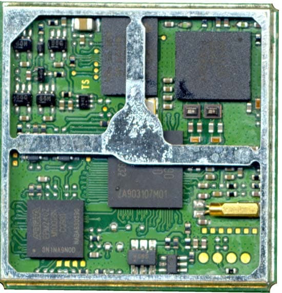
Click to zoom
Application Details
- Equipment Class
- PCB - PCS Licensed Transmitter
- Date of Grant
- Apr 20, 2010
- Application Purpose
- Original Equipment
- Date of Application
- Apr 20, 2010
- Equipment Note
- Quadband GSM/ GPRS Module
- Frequency Range
- 1850.20000000 - 1909.80000000
- Company
- Telit Communications S.p.A.
- Country
- Italy
Documents & Files
Document Text
Text extracted from the exhibit documents filed with the FCC. Open a document above to read the original.
Users Manual
GE864-QUAD Hardware User Guide For GE864-QUAD 1vv0300872 Rev.1 2010-04-02 GE864-QUAD Hardware User Guide 1vv0300872 Rev.1 2010-04-02 - All Rights Reserved. Page 2 of 77 APPLICABILITY TABLE PRODUCT GE864-QUAD GE864-QUAD Hardware User Guide 1vv0300872 Rev.1 2010-04-02 - All Rights Reserved. Page 3 of 77 DISCLAIMER The information contained in this document is the proprietary information of Telit Communications S.p.A. and its affiliates (“TELIT”). The contents are confidential and any disclosure to persons other than the officers, employees, agents or subcontractors of the owner or licensee of this document, without the prior written consent of Telit, is strictly prohibited. Telit makes every effort to ensure the quality of the information it makes available. Notwithstanding the foregoing, Telit does not make any warranty as to the information contained herein, and does not accept any liability for any injury, loss or damage of any kind incurred by use of or reliance upon the information. Telit disclaims any and all responsibility for the application of the devices characterized in this document, and notes that the application of the device must comply with the safety standards of the applicable country, and where applicable, with the relevant wiring rules. Telit reserves the right to make modifications, additions and deletions to this document due to typographical errors, inaccurate information, or improvements to programs and/or equipment at any time and without notice. Such changes will, nevertheless be incorporated into new editions of this document. Copyright: Transmittal, reproduction, dissemination and/or editing of this document as well as utilization of its contents and communication thereof to others without express authorization are prohibited. Offenders will be held liable for payment of damages. All rights are reserved. Copyright © Telit Communications S.p.A. 2010 GE864-QUAD Hardware User Guide 1vv0300872 Rev.1 2010-04-02 - All Rights Reserved. Page 4 of 77 Contents APPLICABILITY TABLE ........................................................................................................................................................ 2 1. INTRODUCTION .................................................................................................................................................... 7 1.1. SCOPE .................................................................................................................................................................... 7 1.2. AUDIENCE............................................................................................................................................................... 7 1.3. CONTACT INFORMATION, SUPPORT ............................................................................................................................. 7 1.4. DOCUMENT ORGANIZATION ....................................................................................................................................... 8 1.5. TEXT CONVENTIONS ................................................................................................................................................. 9 1.6. RELATED DOCUMENTS .............................................................................................................................................. 9 1.7. DOCUMENT HISTORY .............................................................................................................................................. 10 2. OVERVIEW .......................................................................................................................................................... 11 3. GE864 MECHANICAL DIMENSIONS ..................................................................................................................... 12 4. GE864 MODULE CONNECTIONS .......................................................................................................................... 13 4.1. PIN-OUT ........................................................................................................................................................... 13 4.1.1. BGA Balls Layout ................................................................................................................................... 17 5. HARDWARE COMMANDS ................................................................................................................................... 19 5.1. TURNING ON THE GE864-QUAD ........................................................................................................................ 19 5.2. TURNING OFF THE GE864-QUAD ...................................................................................................................... 21 5.2.1. Hardware Unconditional Restart........................................................................................................ 22 6. POWER SUPPLY .................................................................................................................................................. 25 6.1. POWER SUPPLY REQUIREMENTS ......................................................................................................................... 25 6.2. GENERAL DESIGN RULES .................................................................................................................................... 27 6.2.1. Electrical Design Guidelines ............................................................................................................... 27 6.2.1.1. +5V input Source Power Supply Design Guidelines ............................................................................................... 27 6.2.1.2. +12V input Source Power Supply Design Guidelines ............................................................................................. 28 6.2.1.3. Battery Source Power Supply Design Guidelines ...........................................…
Text truncated - open the document above for the full version.
Cover Letter(s)
/ Telit AGENCY LETTER Communication'S S.pA Trieste, 03th July2009 To whom it may concem This is to certify that relit Communications S.p.A. authorises Telecommunication Certification Body RFI Global Services ltd Pavilion A Ashwood Park Ashwood Way Basingstoke Hampshire RG23 8BG England. to act on our behalf for the application of the EUTto RFI Global Services ltd. Telecommunication Certification Body. We certify that we are not subject to a denial of Federal benefits, that include FCC benefits, pursuant to Section 5301 of the Anti-Drug Abuse Act of 1988, 21 U.S.C. § 862 because of a conviction for possession or distribution of a controlled substance. See 47 CFR 1.2002(b) for the definition of a "party" for these purposes. Yours sinC~relY Telit Communications S.p.A Via Stazione di Prosecco, 5tb 34010 Sgonico (TRIESTE)ITALY u.. PA _J
External Photos
TECHNICAL MANUAL Telit GE864-QUAD CL2 Quad Band GPRS Data Terminal System Pag.12 of 17 Rev. 0 4 PHOTOS AND ASSEMBLIES 4.1 Telit GE864-QUAD CL2 Module Final assembly TECHNICAL MANUAL Telit GE864-QUAD CL2 Quad Band GPRS Data Terminal System Pag.13 of 17 Rev. 0 4.2 CS1376b PCB primary layer TECHNICAL MANUAL Telit GE864-QUAD CL2 Quad Band GPRS Data Terminal System Pag.14 of 17 Rev. 0 4.3 CS1376b PCB secondary layer
ID Label/Location Info
TECHNICAL MANUAL Telit GE864-QUAD CL2 Quad Band GPRS Data Terminal System Pag.11 of 17 Rev. 0 3 LABEL LAYOUT The only purpose of this document is to show the layout. Do not use it to print the real label. Raw label code: 1vv0200772 Dimensions: 25 x 25mm
Internal Photos
TECHNICAL MANUAL Telit GE864-QUAD CL2 Quad Band GPRS Data Terminal System Pag.12 of 17 Rev. 0 4 PHOTOS AND ASSEMBLIES 4.1 Telit GE864-QUAD CL2 Module Final assembly TECHNICAL MANUAL Telit GE864-QUAD CL2 Quad Band GPRS Data Terminal System Pag.13 of 17 Rev. 0 4.2 CS1376b PCB primary layer TECHNICAL MANUAL Telit GE864-QUAD CL2 Quad Band GPRS Data Terminal System Pag.14 of 17 Rev. 0 4.3 CS1376b PCB secondary layer
Operational Description
GE864 and GC864 Product Description 80273ST10008a Rev. 17 - 2009-12-01 Telit GE864 and GC8 64 Product Description 80273ST10008a Rev. 17-2009-12-01 Reproduction forbidden without Telit Communications S.p.A. written authorization - All Rights Reserved page 2 of 69 APPLICABILITY TABLE The information contained in this document is referred to the following products: Telit GE864 and GC8 64 Product Description 80273ST10008a Rev. 17-2009-12-01 Reproduction forbidden without Telit Communications S.p.A. written authorization - All Rights Reserved page 3 of 69 DISCLAIMER The information contained in this document is the proprietary information of Telit Communications S.p.A. and its affiliates (“TELIT”). The contents are confidential and any disclosure to persons other than the officers, employees, agents or subcontractors of the owner or licensee of this document, without the prior written consent of Telit, is strictly prohibited. Telit makes every effort to ensure the quality of the information it makes available. Notwithstanding the foregoing, Telit does not make any warranty as to the information contained herein, and does not accept any liability for any injury, loss or damage of any kind incurred by use of or reliance upon the information. Telit disclaims any and all responsibility for the application of the devices characterized in this document, and notes that the application of the device must comply with the safety standards of the applicable country, and where applicable, with the relevant wiring rules. Telit reserves the right to make modifications, additions and deletions to this document due to typographical errors, inaccurate information, or improvements to programs and/or equipment at any time and without notice. Such changes will, nevertheless be incorporated into new editions of this document. Copyright: Transmittal, reproduction, dissemination and/or editing of this document as well as utilization of its contents and communication thereof to others without express authorization are prohibited. Offenders will be held liable for payment of damages. All rights are reserved. Copyright © Telit Communications S.p.A. 2009. Telit GE864 and GC8 64 Product Description 80273ST10008a Rev. 17-2009-12-01 Reproduction forbidden without Telit Communications S.p.A. written authorization - All Rights Reserved page 4 of 69 Contents 1. INTRODUCTION..................................................................................................................................................... 7 1.1. AUDIENCE..................................................................................................................................................................7 1.2. CONTACT INFORMATION, SUPPORT.............................................................................................................................7 1.3. DOCUMENT ORGANIZATION.........................................................................................................................................7 1.4. TEXT CONVENTIONS...................................................................................................................................................8 1.5. RELATED DOCUMENTS................................................................................................................................................9 1.6. DOCUMENT HISTORY..................................................................................................................................................9 2. OVERVIEW .......................................................................................................................................................... 13 3. GENERAL PRODUCT DESCRIPTION........................................................................................................................ 15 3.1. DIMENSIONS............................................................................................................................................................15 3.1.1. GE864-QUAD/PY.........................................................................................................................................15 3.1.2. GC864-QUAD/PY with and without SIM Holder......................................................................................16 3.2. WEIGHT...................................................................................................................................................................17 3.3. ENVIRONMENTAL REQUIREMENTS.............................................................................................................................17 3.3.1. Temperature range...................................................................................................................................17 3.3.2. Vibration Test (non functional)................................................................................................................17 3.3.3. RoHS compliance.......................................................................................................................................18 3.4. OPERATING FREQUENCY...........................................................................................................................................18 3.5. TRANSMITTER OUTPUT POWER..................................................................................................................................18 3.6. REFERENCE SENSITIVITY..........................................................................................................................................19 3.7. ANTENNA................................................................................................................................................................20 3.7.1. GC864 QUAD/PY RF antenna connector..................................................................................................20 3.8. SUPPLY VOLTAGE............................…
Text truncated - open the document above for the full version.
RF Exposure Info
Page 1of 3 Documentazione riservata. Questo documento non può essere riprodotto, anche parzialmente, né reso noto a terzi senza pr eventiva autorizzazione scritta diTelit Communications S.p.A. Tutti i diritti sono tutelati a norma di legge. Restricted document. No part of this document can be reproduced or copied in any format, in part or totally, nor its contents revealed in any manner to others without the express written permission of Telit Communications S.p.A. All rights reserved. CONFIDENTIAL MOD. 106 04/09 Rev.0 MPE Calculation for GE864-QUAD CL2 - OET Bulletin 65 The FCC requires that the calculated MPE be equal to or less than a given limit dependent on frequency at a distance of 20 cm from a device to the body of a user. The transmitter operation for the GE864-QUAD CL2 covers GSM850 and PCS1900 operating bands. The following FCC Rule Parts are applicable: Part 2.1091(c) Part 22 GSM850 devices operating at frequencies at or below 1.5GHz with effective radiated power (ERP) of 1.5 watts or more are subject to routine RF exposure evaluation, otherwise they are categorically excluded. Part 24 PCS1900 devices operating at frequencies above 1.5GHz with effective radiated power (ERP) of 3 watts or more are subject to routine RF exposure evaluation, otherwise they are categorically excluded. Part 24.232 (b) Mobile/ Portable stations are limited to 2 Watts EIRP peak power Part 22.913 (a)(2) The ERP of mobile transmitters and auxiliary test transmitters must not exceed 7 Watts. The MPE calculation as given in FCC OET Bulletin 65, page 19 is used to calculate the safe operating distance for the user. S = EIRP/4 π R2 Where S = Power density EIRP = Effective Isotropic Radiated Power (EIRP = P x G) P = Conducted Transmitter Power G = Antenna Gain (relative to an isotropic radiator) R = distance to the centre of radiation of the antenna For GSM 850 Transmitter frequency range = 824MHz to 849MHz Max. Conducted Transmitter Power = 33dBm (2.0W) @ antenna socket From Part 2.1091(c) routine RF exposure evaluation is required for ERP> 1.5W. Antenna use with gains above 0.86dBi would therefore require RF exposure evaluation. ie: EIRP = 33 +0.86 = 33.86dBm for 0.86dBi antenna ERP = EIRP – 2.1dB (half wave dipole gain) ERP = 33.86 – 2.1 = 31.67dBm (1.5W limit) Page 2of 3 Documentazione riservata. Questo documento non può essere riprodotto, anche parzialmente, né reso noto a terzi senza pr eventiva autorizzazione scritta diTelit Communications S.p.A. Tutti i diritti sono tutelati a norma di legge. Restricted document. No part of this document can be reproduced or copied in any format, in part or totally, nor its contents revealed in any manner to others without the express written permission of Telit Communications S.p.A. All rights reserved. CONFIDENTIAL MOD. 106 04/09 Rev.0 MPE Requirement From table 1 (b) - Limits for General Population/ Uncontrolled Exposure of FCC Rule Part 1.1310 for GSM850 S = f/1500 mW/cm2 (f = operating frequency) S = 824/1500 = 0.55 mW/cm2 (worst case) MPE Calculation to Determine Safe Maximum Antenna Gain (G) Values: S = 0.55 mW/cm2 P = 2000mW R = 20cm S = PxG/4 π R2 0.55 = 2000xG/(12.56 x 202) 0.55 x (12.56 x 202) = 2000 x G 0.55 x (12.56 x 202)/ 2000 = G G = 1.38 (1.40dBi) Calculation for Maximum radiated power output For 1.4dBi gain antenna Power = 1.38 x 2.0 = 2.76W EIRP (34.4dBm) ERP = EIRP – 2.1dB (half wave dipole gain) Max. ERP = 34.4 – 2.1dBm = 32.3dBm This is below the Part 22.913 (a)(2) limit of 7W ERP The 1.4dBi maximum gain antenna will therefore comply with the required FCC rule parts. For PCS1900 Transmitter frequency range = 1850MHz to 1910MHz Max. Conducted Transmitter Power P = 30dBm (1.0W) @ antenna socket Calculation for Maximum radiated power output Maximum antenna gain G that can be used to comply with the maximum transmitter power limit of 2W EIRP of Part 24.232(b) is calculated as: P x G = 2 ie: G = 2/1 = 2 (3dBi) For 3dBi antenna gain maximum ERP is < 3.0W, so from Part 2.1091(c), routine RF exposure evaluation is categorically excluded. The 3dBi maximum gain antenna will therefore comply with the required FCC rule parts. Page 3of 3 Documentazione riservata. Questo documento non può essere riprodotto, anche parzialmente, né reso noto a terzi senza pr eventiva autorizzazione scritta diTelit Communications S.p.A. Tutti i diritti sono tutelati a norma di legge. Restricted document. No part of this document can be reproduced or copied in any format, in part or totally, nor its contents revealed in any manner to others without the express written permission of Telit Communications S.p.A. All rights reserved. CONFIDENTIAL MOD. 106 04/09 Rev.0 Conclusion The required 20cm RF exposure limits for General Population/ Uncontrolled Exposure FCC Rule Part 1.1310, and ERP Part 22.913 (a)(2), EIRP Part 24.232 (b) maximum transmitter power limits will not be exceeded for the GE864-QUAD CL2 using antennas having a maximum gain of 1.4dBi (850MHz) and 3.0dBi (1900MHz) respectively.
Test Report
TEST REPORT FROM RFI GLOBAL SERVICES LTD Test of: GE864-QUAD To: FCC Part 22: 2009 Subpart H, FCC Part 24: 2009 Subpart E, RSS 132 Issue 2 September 2005 and RSS-133 Issue 5 February 2009 Test Report Serial No: RFI/RPT4/RP76660JD03A Supersedes Test Report Serial No: RFI/RPT3/RP76660JD03A This Test Report Is Issued Under The Authority Of Brian Watson, COO Payments and Consultancy: Checked By: Nigel Davison Signature: Date of Issue: 20 April 2010 This report is issued in Adobe Acrobat portable document format (PDF). It is only a valid copy of the report if it is being viewed in PDF format with the following security options not allowed: Changing the document, Selecting text and graphics, Adding or changing notes and form fields. This report may not be reproduced other than in full, except with the prior written approval of RFI Global Services Ltd. The results in this report apply only to the sample(s) tested. TEST REPORT SERIAL NO: RFI/RPT4/RP76660JD03A ISSUE DATE: 20 APRIL 2010 Page 2 of 56 RFI Global Services Ltd This page has been left intentionally blank. TEST REPORT SERIAL NO: RFI/RPT4/RP76660JD03A ISSUE DATE: 20 APRIL 2010 RFI Global Services Ltd Page 3 of 56 Table of Contents 1. Customer Information .................................................................................................................. 4 2. Summary of Testing ..................................................................................................................... 5 3. Equipment Under Test (EUT) ....................................................................................................... 9 4. Operation and Monitoring of the EUT during Testing ............................................................. 12 5. Measurements, Examinations and Derived Results ................................................................ 13 6. Measurement Uncertainty .......................................................................................................... 54 Appendix 1. Test Equipment Used ................................................................................................55 TEST REPORT SERIAL NO: RFI/RPT4/RP76660JD03A ISSUE DATE: 20 APRIL 2010 Page 4 of 56 RFI Global Services Ltd 1. Customer Information Company Name: Telit Communications S.p.A. Address: Via Stazione di Prosecco, 5/B Sgonico TS 34010 Italy TEST REPORT SERIAL NO: RFI/RPT4/RP76660JD03A ISSUE DATE: 20 APRIL 2010 RFI Global Services Ltd Page 5 of 56 2. Summary of Testing 2.1. General Information – FCC Part 22 Specification Reference: 47CFR22 Specification Title: Code of Federal Regulations Volume 47 (Telecommunications) 2009: Part 22 Subpart H (Public Mobile Services) Specification Reference: RSS-GEN Issue 2 June 2007 Specification Title: General Requirements and Information for the Certification of Radio communication Equipment Specification Reference: RSS-132 Issue 2 Sep 2005 Specification Title: Cellular Telephones Employing New Technologies Operating in the Bands 824-849 MHz and 869-894 MHz Specification Reference: RSS-133 Issue 5 Feb 2009 Specification Title: GHz Personal Communications Services Specification Reference: SRSP-510 Issue 4 Feb 2008 Specification Title: Technical Requirements for Personal Communications Services in the Bands 1850-1915 MHz and 1930-1995 MHz Specification Reference: SRSP-503 Issue 6 Jun 2003 Specification Title: Technical Requirements for Cellular Radiotelephone Systems Operating in the Bands 824 – 849 MHz and 869 – 894 MHz Site Registration: FCC: 209735 Industry Canada: 3245B-2 Location of Testing: RFI Global Services Ltd, Wade Road, Basingstoke, Hampshire, RG24 8AH. Test Dates: 02 March 2010 to 19 April 2010 TEST REPORT SERIAL NO: RFI/RPT4/RP76660JD03A ISSUE DATE: 20 APRIL 2010 Page 6 of 56 RFI Global Services Ltd 2.2. Summary of Test Results – FCC Part 22 FCC Reference (47CFR ) IC Reference Measurement Result FCC Part 15.109 RSS-Gen 4.10/6.0 RSS-132 4.6 Receiver/Idle Mode Radiated Spurious Emissions FCC Part 22.913(a) RSS-132 4.4 SRSP-503 5.1.3 Transmitter Carrier Output Power and Effective Radiated Power (ERP) FCC Part 22.355 RSS-132 4.3 RSS Gen 4.7 Transmitter Frequency Stability (Temperature Variation) FCC Part 22.355 RSS-132 4.3 RSS Gen 4.7 Transmitter Frequency Stability (Voltage Variation) FCC Part 2.1049 RSS-Gen 4.6.1 Transmitter Occupied Bandwidth FCC Part 2.1051/22.917 RSS-132 4.5 Transmitter Out of Band Conducted Emissions FCC Part 2.1051/22.917 RSS-132 4.5 Transmitter Conducted Emissions at Band Edges FCC Part 2.1053/22.917 RSS-132 4.5 Transmitter Out of Band Radiated Emissions FCC Part 2.1053/22.917 RSS-132 4.5 Transmitter Band Edge Radiated Emissions *Note Key to Results = Complied = Did not comply Note(s): 1. Transmitter Band Edge Radiated Emissions was not performed for GSM850, as the residual carrier power seen on the emissions plot is lower than the specified -13.0dBm limit and therefore complies with the band edge limit by inspection. TEST REPORT SERIAL NO: RFI/RPT4/RP76660JD03A ISSUE DATE: 20 APRIL 2010 RFI Global Services Ltd Page 7 of 56 2.3. General Information – FCC Part 24 Specification Reference: 47CFR24 Specification Title: Code of Federal Regulations Volume 47 (Telecommunications) 2009: Part 24 Subpart E (Personal Communication Services) Specification Reference: RSS-GEN Issue 2 June 2007 Specification Title: General Requirements and Information for the Certification of Radiocommunication Equipment Specification Reference: RSS-133 Issue 5 Feb 2009 Specification Title: GHz Personal Communications Services Specification Reference: SRSP-510 Issue 4 Feb 2008 Specification Title: Technical Requirements for Personal Communications Services (PCS) in the Bands 1850-1915 MHz and 1930-1995 MHz Site Registration: FCC: 209735 Industry Canada: 3245B-2 Location of Testing: RFI Global Services Ltd, Wade Road, Basingstoke, Hampshire, RG24 8AH. Test Dates: 02 March to 19 April 2010 TEST REPORT SERIAL NO: RFI/RPT4/RP76660JD03A ISSUE DATE: 20 APRIL 2010 Page 8 of 56 RFI …
Text truncated - open the document above for the full version.
Contact Information
Applicant
Paolomaria Schiratti(VP Global Certification)
Technical Contact
Telit Communications S.p.A.Fabrizio Druscovich
[email protected]39 040 4192 111
Viale Stazione di Prosecco 5/b · Trieste · Italy
Non-Technical Contact
Telit Communications S.p.A.Fabrizio Druscovich
[email protected]39 040 4192 111
Test Firm
UL VS LtdDarren Rust
Technical Specifications
| # | Rule Parts | Frequency Range | Power Output | Emission | Tolerance |
|---|---|---|---|---|---|
| 2 | 24E | 1.85 GHz - 1.91 GHz | 760.00 mW | 300KGXW | 120 Hz |
Other Applications from Telit Communications S.p.A.
RI7FE910C04WWI
Jul 01, 20265G Radio Module
Equipment Class
PCB - PCS Licensed TransmitterRI7FE910C04NA
Jun 23, 20265G Radio Module
Equipment Class
CBE - Citizens Band End User DevicesRI7LE910T1SN
Apr 09, 2026LE910T1-SN
Equipment Class
JBP - Part 15 Class B Computing Device PeripheralRI7ME310T1W1
Mar 11, 2026ME310T1-W1
Equipment Class
PCB - PCS Licensed TransmitterRI7LE310X1LA
Jan 08, 2026LTE Cat 1 bis module
Equipment Class
JBP - Part 15 Class B Computing Device Peripheral